

Page 1
NLP Series Nolan Fluorescent Pendant
Model 520
Safety Precautions
Read all safety precautions and installation instructions carefully
before installing or servicing this fixture. Failure to comply with
these instructions could result in potentially fatal electric shock
and/or property damage.
It is recommended that a qualified electrician perform all wiring. This
fixture must be wired in accordance with all national and local
electrical codes.
Do not handle any energized fixture or attempt to energize any
fixture with wet hands or while standing on a wet or damp surface or
in water.
Assembly Instructions
1. Preparing for installation
A. Disconnect electrical power before installing or
servicing any part of this fixture.
B. Secure the canopy mounting plate (6) to junction box
(not supplied) with screws provided.
C. NOTE: This unit comes with 2-12” and 2-24” stems
for optional height mounting. Loctite all stems with
supplied Loctite to prevent stems from coming
undone.
2. Wiring and Fixture Mounting
Caution: Make sure power is off at fuse or circuit breaker
box. If power supply wires are within three inches of
ballast use wire suitable for at least 90C (194F). Note:
Most dwellings built before 1985 have supply wire rated to
60C. Consult a qualified electrician before installing.
A. This unit may not operate properly unless connected to
a “grounded” electrical circuit. Securely attach green
(or green and yellow) wire to green ground screw on
canopy mounting plate (6) with provided hardware.
Pull supply wires through hole in center of canopy
mounting plate (6).
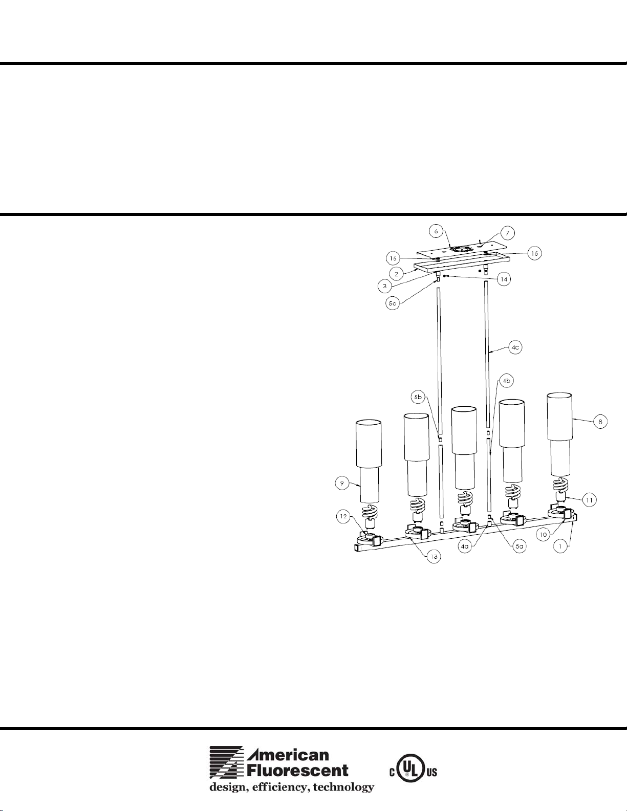
C. Feed black and white wires through desired stem on
side where wire exits out from channel (1). Verify
there is a threaded nipple (4a) in between stem (5b)
and stem base (4a).
D. Attached desired stem length to lower housing (1) stem
base (4a) and turn clockwise to fasten. Feed black and white wires through the next stem (4b), verifying there is a
threaded nipple (5b) between the stem sets. Repeat for stem and nipple set (4c, 5c). Turn clockwise to fasten. Feed
black and white wire through swivel (3) and fasten.
E. Attach swivels (3) to canopy (2) and secure with lock washer (15) and hex nut (16).
F. Using wire connectors provided, connect white supply wire to white fixture lead. Connect black hot supply wire
to black fixture lead. Do not mix wires. Pull on each wire to make sure connections are secure. Make certain no
bare wires are exposed outside of wire connectors.
G. Align canopy (2) with canopy mounting plate (6) studs (7) through holes in canopy (2) and secure with thumbnuts
(14).
This fixture is designed for use in a 110-120VAC, 60Hz. (Self-
Ballasted dimmable CFL) This fixture is usable on a dimming
circuit with dimmable lamps and specified dimmers.
To reduce the risk of electrical shock, and to assure proper operation,
this fixture must be adequately grounded. To accomplish proper
grounding, there must be a separate ground wire (green) or bare metal
contact (metal conduit) between this fixture and the ground
connection of your main power supply panel. The green ground
screw location is clearly marked on the gem bar.
This fixture is intended to be used for general indoor lighting in dry
or damp locations only.
Page 1 of 1 8060521 rev 1
Page 2

NLP Series Nolan Fluorescent Pendant
prop
Model 520
3.
Lamp and Diffuser installation
A. (See Detail A) Install lamps (11) into socket base (12). Usable on dimming circuit with dimmable GU24 base
lamps, use only GU24 base dimmable lamps with a dimming control (26W max.). To install, line up lamp pins
with the corresponding holes in lamp socket and turn clockwise until a click is heard. Repeat for each lamp.
B. Place inner diffuser (9) onto channel and center, place outer diffuser (8) over inner diffuser and adjust if needed.
Repeat for each diffuser assembly.
C. Restore power at fuse or circuit breaker box.
DETAIL A
Limited Factory Warranty
American Fluorescent Corporation hereby warranty that this fixture is free from defects in materials and workmanship when installed and used under normal operating
conditions for a period of 2 years from date of purchase. This warranty covers all component parts and extends only to replacement of defective fixture or components;
it does not cover failure due to im
er installation, misuse, mishandling or damage incurred in transit.
Page 2 of 2 8060521 rev 1
 Loading...