

Page 1
NLL Pro Series LED Undercabinet Fixture
Models NLLP9, NLLP14, NLLP22, NLLP32 & NLLP40 Plug-in or Hard Wire, Linkable
Safety Precautions
Read all safety precautions and installation instructions carefully
before installing or servicing this fixture. Failure to comply with
these instructions could result in potentially fatal electric shock
and/or property damage.
It is recommended that a qualified electrician perform all wiring. This
fixture must be wired in accordance with all national and local
electrical codes.
Do not handle an energized fixture or attempt to energize any fixture
with wet hands or while standing on a wet or damp surface or in
water.
Make sure that the power source conforms to the requirements of the
fixture. (See labels on fixture housing).
Assembly Instructions
1. Preparation for Installation
A. Disconnect electrical power before installing or servicing any part of this fixture.
B. Place fixture on a clean flat surface.
C. Determine input power connection method (Cord, Hardwire or Link) and follow corresponding directions below.
2. Cord to Outlet Installation
(Skip this step if using Hardwire or Link-to-Fixture
Installation)
A. Fixture must be mounted within 5’ of an outlet. Locate the 5’ power
cord included in the box.
B. Connect Cord to fixture by snapping the quick connect end of the
cord to the corresponding connector in the end of the fixture marked
“IN”. The cord will only connect to the “IN” connector so make the
right connector is identified. Do not force the connection, it should
snap in easily.
C. Follow the directions for Mounting below.
D. Once Mounting is completed, plug the cord into the outlet.
E. The unit can now be turned on with the Power switch (7a). By
flipping the switch (7a) select between one of the 3 modes (Lo, Off, Hi ).
Switch (6a) is used to change the color temperature of light delivered 2700K, 3000K & 4000K
CCT respectively.
3. Hardwire Installation Preparation
(Skip this step if using Cord to Outlet or Link-to-Fixture Installation to Power Unit)
A. Discard Cord if Hardwire Installation is used.
B. Disengage cover (5) by loosening screw.
C. Remove appropriate 3/8” diameter knockout for supply wiring entry.
D. Determine appropriate connector:
i) Cable connector is included.
ii) Flexible conduit BX (AC) 3/8”trade size cable (8)
(not included).
iii) Anti-short bushing (not included).
E. Insert cable connector (7) into the housing open hole.
Secure it with the nut.
F. Determined the length of BX cable (8) and add about 5”
or an appropriate length for the stripping purposes. Cut
the required length of the cable. Trim away the
insulation. Push the exposed wires (hot, neutral and
ground) through the anti-short bushing and slide this
bushing all the way down to the exposed wires until it is
snug up against the armor.
G. Follow the directions below for Mounting, and then
proceed to Hardwire Installation Completion.
To reduce the risk of electrical shock, and to assure proper operation,
this fixture must be adequately grounded.
Do not touch LED light engine or heat-sink.
12-inch minimum spacing distance from luminaire
required for all objects located under fixture.
This fixture is to be used for general indoor lighting in dry locations
only. Linkable total wattage is 200 Watts
This fixture is dimmable in the high (II) setting only. The following
dimmers are approved for use to achieve smooth dimming down to
10% of full scale:
Leviton – 6633, 6681, 6621-WWP, 6631-WWP
Lutron – TG-600P, TG-603P, AY600P, MACL153MH, SELV-300P
Legrand / Pass & Seymour – T600WV, WS700TCCCVG
Cooper – 6013W
Page 1 of 2 8060795 Rev 0
Page 2
NLL Pro Series LED Undercabinet Fixture
Models NLLP9, NLLP14, NLLP22, NLLP32 & NLLP40 Plug-in or Hard Wire, Linkable
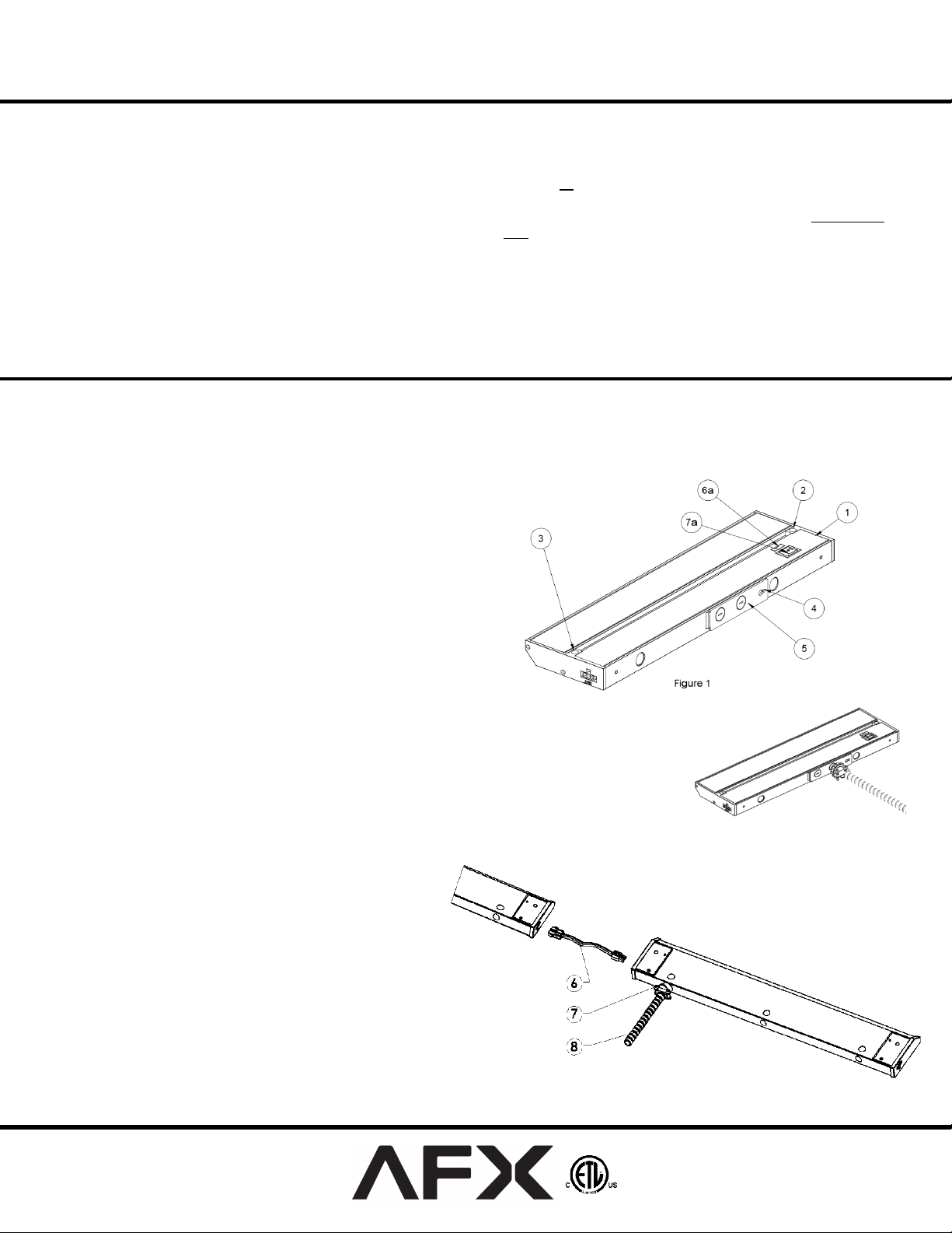
4. Link-to-Fixture Installation
(Skip this step if using Hardwire or Cord to Outlet Installation.)
A. First fixture in series can be Corded or Hardwired
B. Second fixture must be located within 12” of first fixture.
C. Make sure power is off on all fixtures. The fixture switch should not be engaged in either direction (7) .
D. Connect the Linking cord (6) to the “Out” connector of the first fixture and into the “In” connector of the second fixture.
(The connectors are keyed to only fit one way. Do not force the connections, they should snap in easily.)
E. Follow directions in Mounting Section.
F. Once mounting is completed, energize the first fixture. (Each fixture is controlled individually.)
Note: Injury to persons and damage to the mounting surface may result if the fixture or mounting hardware is pulled from the mounting
location. To reduce the possibility of such injury, be sure to mount the fixture only on a surface that is mechanically, structurally sound.
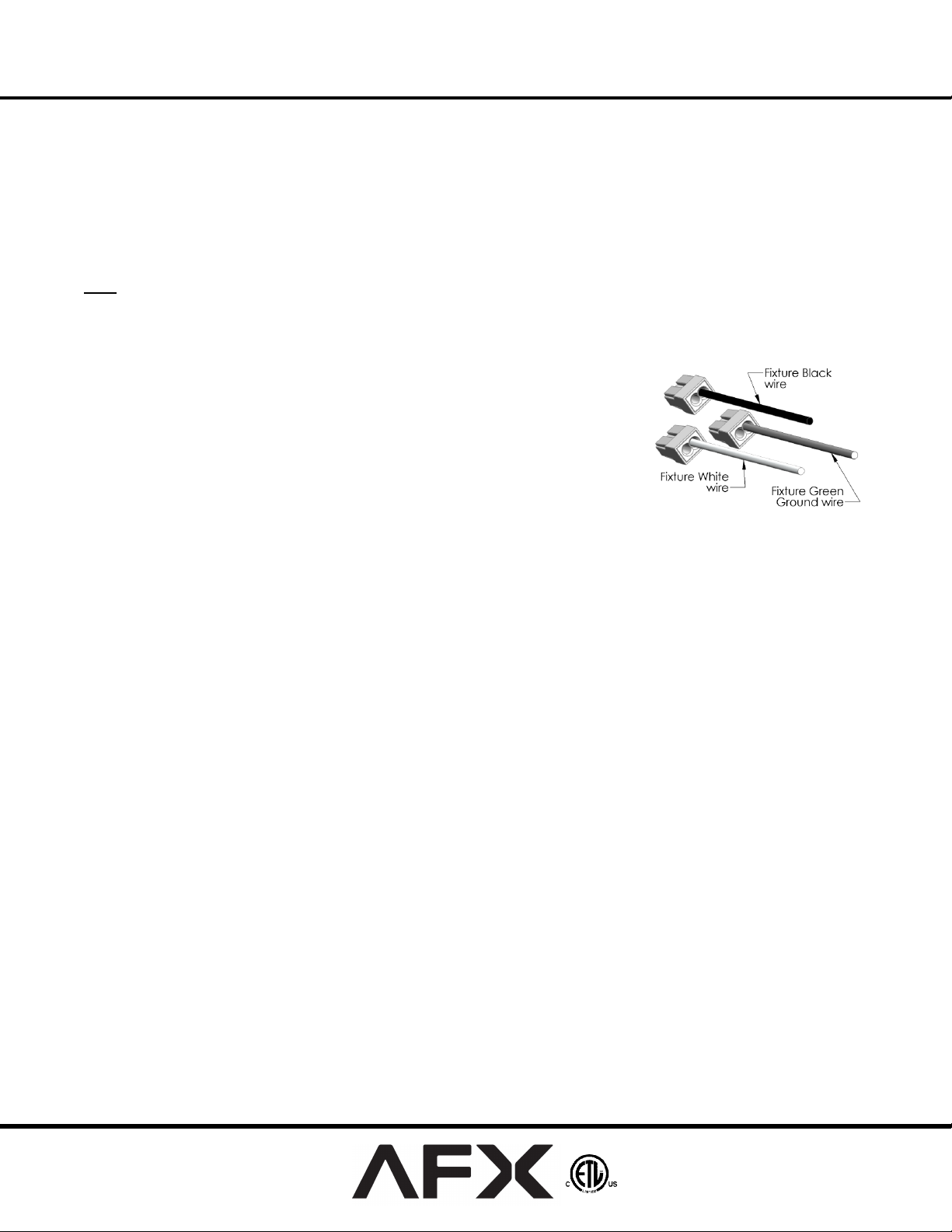
5. Hardwire Installation Completion
a. Pull 3 wires out of the fixture to allow connection to the branch circuit.
b. Connect the Green ground input supply wire to the fixture Green ground wire.
Do this by inserting it into the open hole in the push-in wire connector (included)
that is attached to the Green ground wire in the fixture.
c. Connect the White input supply wire to the fixture White wire. Do this by
inserting it into the open hole in the push-in wire connector (included) that is
attached to the White wire in the fixture.
d. Connect the Black input supply wire to the fixture Black wire. Do this by
inserting it into the open hole in the push-in wire connector (included) that is
attached to the Black wire in the fixture. Do not mix wires or change
polarity.
e. Pull on each wire lead to make sure connections are secure. Make certain no bare wires are exposed outside of the wire
connectors.
f. Feed wires back into fixture, reattach adapter plate tighten screw, and attach the fixture to the base of the cabinet, with screws (2
& 3) as defined in mounting section.
6. Mounting
A. Using captive screw hole locations for mounting the fixture (2 & 3), position the fixture in location intended for mounting. Mark hole
locations by using the screw-holes as a guide. Drill suitable holes in the marked positions. Mount the housing to desired surface with the 2
captive screws (Ref # 2 & 3 in Figure 1).
Limited Factory Warranty
AFX Inc. warrants this fixture is free from defects in materials and workmanship when installed and used under normal operating conditions for a period
of 5 years from date of purchase. This warranty covers all component parts and extends only to replacement of defective fixture or components; it does
not cover failure due to improper installation, misuse, mishandling or damage incurred in transit.
Page 2 of 2 8060795 Rev 0
 Loading...