

Page 1
Make sure that the power source conforms to the
requirements of the fixture.
4
Mounting screws or Toggle bolts
(See labels on fixture housing).
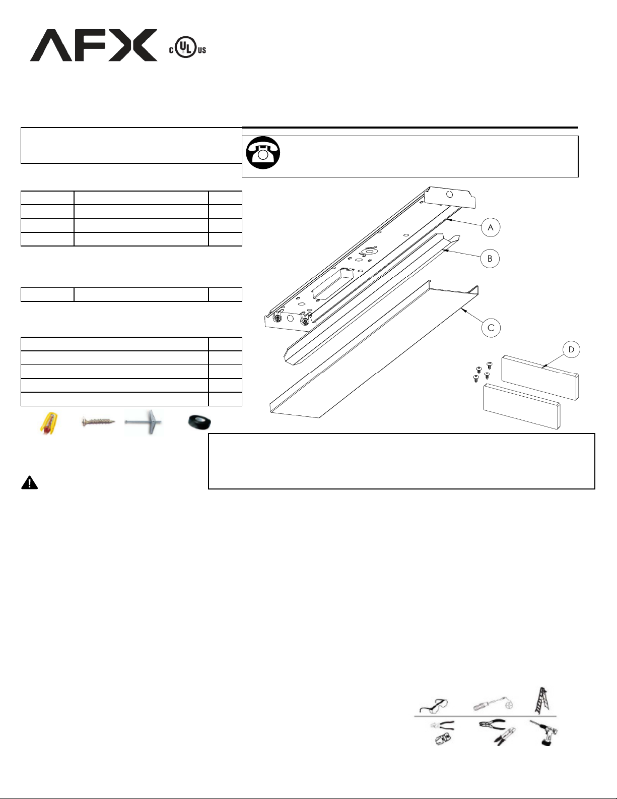
PACKAGE CONTENTS
DescriptionPart
Channel assemblyA
B
C
OPTIONAL (provided with LWK & PLWK)
D Wood endcaps with screws
Ballast cover
Diffuser
Quantity
LINEAR FLUORESCENT WRAP
For 2 or 4 lamp 17watt F17T8, 25watt F25T8 or 32watt F32T8
Questions, problems, missing parts? Before returning to your
retailer, call our customer service department at
1-800-873-2326, 8 a.m.-4 p.m., CST, Monday-Friday.
232 model shown
1
1
1
2
ADDITIONAL PARTS REQUIRED
Description
Wire nuts
T8 Fluorescent lamps only
Electrical tape
WARNINGS AND CAUTIONS
WARNING
Read all safety precautions and installation instructions carefully before installing or servicing this fixture. Failure to comply
•
with these instructions could result in potentially fatal electric shock and/or property damage.
It is recommended that a qualified electrician perform all wiring. This fixture must be wired in accordance with all national
•
and local electrical codes.
•
To reduce the risk of electrical shock, and to assure proper operation, this fixture must be adequately grounded.
CAUTION
Do not handle any energized fixture or attempt to energize any fixture with wet hands or while standing on a wet or damp
•
surface or in water.
•
Disconnect electrical power before installing or servicing any part of this fixture.
•
Not for use with dimmer switch of any kind. (except for D10 models)
(not provided)
Quantity
3
2 or 4
1
Limited Factory Warranty
We hereby warranty that this fixture is free from defects in materials and workmanship when installed and used
under normal operating conditions for a period of 2 years from date of purchase. This warranty covers all component
parts and extends only to replacement of defective fixture or components; it does not cover failure due to improper
installation, misuse, mishandling or damage incurred in transit.
PREPARATION
Before beginning installation of product, make sure all parts are present. Compare parts with package contents list and diagram
above. If any part is missing or damaged, do not attempt to assemble, install or operate the product. Contact customer service
for replacement parts.
Estimated Assembly Time: 20 minutes
•
Tools Required for Assembly: Eye protection, screwdriver, ladder.
•
Helpful Tools: Wire cutter, pliers, stud finder, wire stripper, drill with 1/4 in. bit.
8060318 Rev 2
Page 2

INSTALLATION INSTRUCTIONS
1
Take the channel down and locate the ceiling joists with a
there is a joist use a suitable wood screw (not included) (Fig.4-
Pull the supply power wires from junction box (Fig 5) or power
yoke can be tightened to prevent fixture vibration.
Place ballast cover (Fig. 2-A) onto fixture. Squeeze cover and
Place diffuser (Fig. 7-A) onto fixture. Hang long side onto
CARE AND MAINTAINENCE
TROUBLESHOOTING
Separate the diffuser (Fig. 1-A) from the fixture body (FIG. 1B) by shifting it to one side and pulling it from assembly.
2
Separate the ballast cover from the fixture body by squeezing
it in at dimples (Fig. 2-B) and pulling it from the assembly.
(Fig. 2-A).
3
For models with wood ends – Open two small knockouts in
each metal end cap and attach wood with wood screws
provided into predrilled holes in wood ends.
4
Remove appropriate mounting knockouts (Fig.3-D). Four
located on each side of channel. Determine and remove the
appropriate knockout for power supply wires in channel ( Fig.
3 B or C) or in endcap.
5
Lift fixture up and capture one or more screws in junction box
into the screw retention yoke (Fig. 3-A) until it is captured and
can not be slid back out. Mark the locations of the eight 1/4”
diameter-mounting holes (Fig. 3-D) on the ceiling.
4
stud finder or punch a small hole into the ceiling at each
location using a nail or an awl to see if there is a wood joist. If
Fig. 2
Fig. 1
Fig. 3
A) to mount the channel. Where there is no joist to screw into
use a ¼” toggle bolt (not included) (Fig.4-B) of suitable length
to mount channel securely to the ceiling.
5
supply through the appropriate knockout hole into the fixture.
Secure fixture to ceiling with appropriate mounting hardware
(Fig. 4 A or B). The screw captured in the screw retention
6
Use wire nut to connect white wire from ballast to neutral
supply wire. (Fig. 5-A) Strip supply wires if needed. (Fig. 5-E)
Use wire nut to connect black wire from ballast to power
supply wire. (Fig. 5-B) Cover wire nuts and connections
completely in electrical tape. Secure bare or green ground
wire to green screw in the channel.
7
attach under dimples. (Fig. 2-B) DO NOT PINCH WIRES.
8
Install lamps into fixture. (Fig. 6-A) Each lamp has 2 pins on
each end. Align the pins with slots in socket (Fig. 6-B) and
slide lamp into place. When all 4 pins are in place, rotate
lamp 90°.
9
channel body (Fig. 7-B), swing diffuser up to clear other side
and shift to center.
Fig. 4
Fig. 5
Fig. 6
Fig. 7
Periodically, dust the diffuser (inside and out) with a clean, dry cloth. Wipe clean with a slightly damp cloth as needed. Never use
Problem
Light fails to illum inate.
No flickering.
Light flickers blinks or
lights ends only.
Possible Cause Corrective Action
1. Fixture wiring problem. 1. Check wiring for loos e connections .
2. No power or failed switch. 2. Check power and s witch.
3. Worn-out lamp(s ). 3. Replace lam p(s ) as nee ded.
4. Failed ballast. 4. Replace ballas t as needed.
1. Fixture not properly grounded. 1. Check grounding system.
2. Wrong lamp(s ). 2. Verify lam p is listed on ballas t.
3. One or more failing lam ps . 3. Replace lam ps as needed.
4. Failing ballast. 4. Replace ballas t as needed.
2.
 Loading...