

Page 1
Limited Factory Warranty
AFX Inc. hereby warranty that this fixture is free from defects in materials and workmanship when installed and used under normal operating conditions for a period
of 2 years from date of purchase. This warranty covers all component parts and extends only to replacement of defective fixture or components; it does not cover
failure due to improper installation, misuse, mishandling or damage incurred in transit.
Lancet Series Fluorescent Wall Sconce
Models 118, 126, 213, 218
Safety Precautions
Read all safety precautions and installation instructions carefully
before installing or servicing this fixture. Failure to comply with
these instructions could result in potentially fatal electric shock
and/or property damage.
It is recommended that a qualified electrician perform all wiring. This
fixture must be wired in accordance with all national and local
electrical codes.
Do not handle any energized fixture or attempt to energize any
fixture with wet hands or while standing on a wet or damp surface or
in water.
Assembly Instructions
1. Preparing for installation
A. Disconnect electrical power before installing or
servicing any part of this fixture.
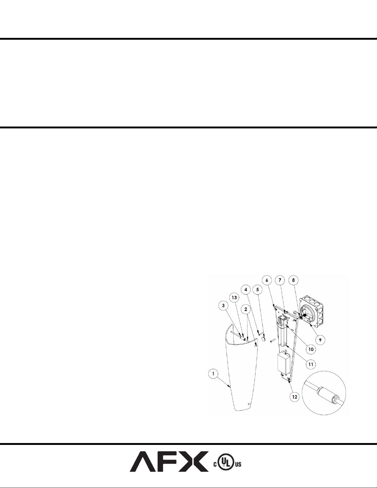
B. Remove diffuser (1) and backpan; separate contents
of hardware bag.
2. Wiring – all wiring must take place inside
junction box
Caution: Make sure power is off at fuse or circuit breaker
box. Check power wires for damage or scrapes. If power
supply wires are within three inches of ballast use wire
suitable for at least 90C (194F). Note: Most dwellings built
before 1985 have supply wire rated to 60C. Consult a qualified
electrician before installing.
A. This unit will not operate properly unless connected
to a “grounded” electrical circuit. Electrical shock,
over heating, low or no light output, and shortened
lamp life can result if proper grounding is not done.
B. Securely attach green (or green and yellow) wire to
fixture backpan ground with green hardware.
C. Using wire nuts, connect white supply wire to white
fixture lead. Connect black supply wire to black
fixture lead. Do not mix wires. Pull on each wire
lead to make sure connections are secure. Make
certain no bare wires are exposed outside of wire
connectors. Note: fixtures with universal voltage
power supplies are pre-wired with a disconnect.
Refer to the included guide for using the disconnect.
3. Mounting
A. If using a plaster ring (not provided) as shown, mount
backpan aligning slots with holes in plaster ring.
Tighten screws (4) securely.
B. If using a junction box only (not provided), attach
cross bar (9) with pipe nipple (8 - provided). Secure
pan to cross bar with screws (4). Use the lock nut to
secure pipe nipple at the proper length.
C. Secure pan with thumbnut (5). Caution: Do not over
tighten. Inspect around fixture to ensure wires are not
caught between edges of back pan and wall.
Make sure that the power source conforms to the requirements of the
fixture (see labels on fixture housing).
To reduce the risk of electrical shock, and to assure proper operation,
this fixture must be adequately grounded. To accomplish proper
grounding, there must be a separate ground wire (green) or bare metal
contact (metal conduit) between this fixture and the ground
connection of your main power supply panel. The green ground
screw location is clearly marked on the fixture housing.
This fixture is intended for use in either a dry or damp indoor
location.
4. Installing Lamp -Install appropriate lamp (11 - not
provided) per label on face of backpan. Insert lamp pins
into lamp holder (10) and press upwards until lamp snaps
in place.
5. Installing Diffuser
A. Insert the long thumbscrews (2) into the top holes of
the diffuser and connect them with the jam nuts (3)
and coupler (13) as shown in the detail view.
B. Insert the short thumbscrews into the bottom holes of
the diffuser and connect them with a coupler only.
C. Tighten thumbscrews until they are flush with the
diffuser. Caution: over-tightening can damage
diffuser.
D. Position assembled lower rod into the bottom pan
hooks (12).
E. Rotate diffuser up & turn top safety tab (7) to the
side. Position assembled upper rod into top hooks (6).
F. Turn top safety tab (7) to position it over upper
mounting rod and tighten screw.
6. Restore power at fuse or circuit breaker box
Page 1 of 1 8060183 R6
 Loading...