

Page 1
LED Sconce Series LED Sconce Light
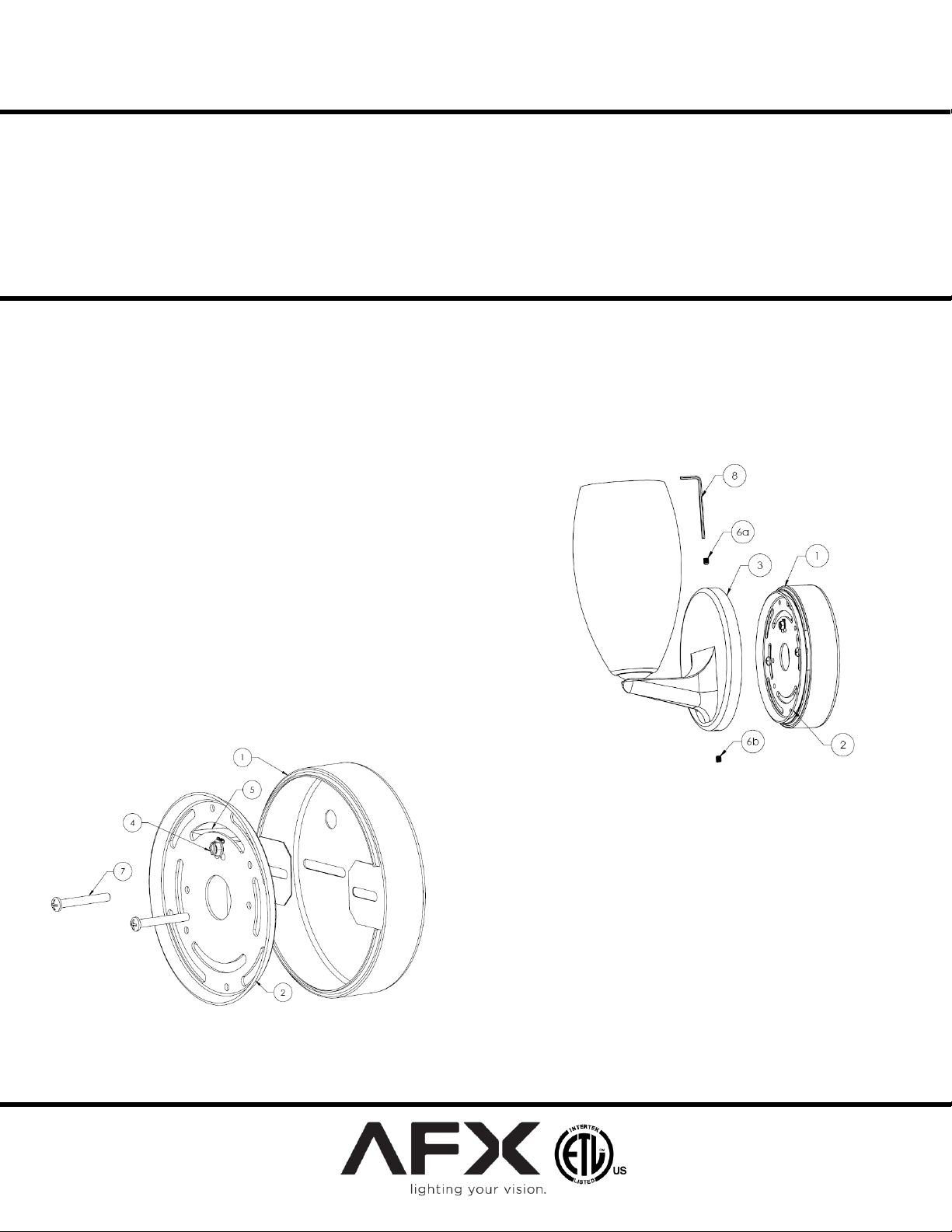
FIGURE 2
FIGURE 1
Limited Factory Warranty
AFX Lighting, Inc. warrants this fixture is free from defects in materials and workmanship when installed and used under normal operating conditions
for a period of 2 years from date of purchase. This warranty covers all component parts and extends only to replacement of defective fixture or
components; it does not cover failure due to improper installation, misuse, mishandling or damage incurred in transit.
Models: BESLXXX & LASLXXX
Safety Precautions
Read all safety precautions and installation instructions carefully before
installing or servicing this fixture. Failure to comply with these instructions
could result in potentially fatal electric shock and/or property damage.
It is recommended that a qualified electrician perform all wiring. This fixture
must be wired in accordance with all national and local electrical codes.
Do not handle any energized fixture or attempt to energize any fixture with
wet hands or while standing on a wet or damp surface or in water.
Assembly Instructions
1. Preparing for Installation -
A. Disconnect electrical power before installing or servicing
any part of this fixture.
B. Remove light fixture, decorative hardware, isolation
canopy and parts bag from carton.
2. Isolation Canopy Wiring and Assembly [Figure 1]
Caution: Make sure power is off at fuse or circuit breaker box.
Check power wires for damage or scrapes. If power supply
wires are within three inches of ballast use wire suitable for at
least 90C (194F). Note: Most dwellings built before 1985 have
supply wire rated to 60C. Consult a qualified electrician before
installing.
A. Assemble circular gem bar (2) and isolation canopy (1) as
shown in Figure 1. Make sure Driver (5) is inside isolation
canopy (1) when assembled. Feed red and blue wires from
LED Driver (5) to front side of circular gem bar (2).
B. Wire the primary side (120VAC, 60Hz) of the LED driver
(5) to the supply wires.
C. Connect black wire from LED Driver (5) to hot supply wire
and secure with large wire nut. Connect white wire from
LED Driver (5) to neutral supply wire and secure with large
wire nut. Connect ground wire to gem bar (2) using green
ground screw (4).
Make sure that the power source conforms to the requirements of the fixture.
(See labels on fixture housing).
To reduce the risk of electrical shock, and to assure proper operation, this
fixture must be adequately grounded. To accomplish proper grounding there
must be a separate ground wire (green) or bare metal contact (metal conduit)
between this fixture and the ground connection of your main power supply
panel. The green ground screw location is clearly marked on the fixture
housing.
This fixture is intended to be used for general lighting in dry or damp
locations only and does not have a mounting orientation requirement.
D. Attach gem bar (2) and isolation canopy (1) to junction box
(not provided) with provided #8 x 1 15/16” long screws (7).
[See figure 1]
3. Fixture Wiring and Assembly [Figure 2]
A. Prepare the outer braided wire (-) and insulated conductor
(+) for wiring onto LED driver.
B. Twist coax cable outer wire braid with blue wire of LED
driver (5) and secure with small wire nut provided. Repeat
this step for joining the inner conductor with the red wire of
the LED driver.
C. Loosen the set screws (6a, 6b) using hex-wrench (8)
provided.
D. Insert any protruding wires between decorative canopy and
isolation canopy.
E. Attach the back plate (3) to the assembled gem bar (2) and
isolation canopy (1). Fasten top set screw (6a) first with the
hex-wrench (8) and repeat with lower set screw (6b).
F. Verify set screws are fastened enough to prevent the back
plate (3) from rotating.
G. Restore power at fuse or circuit breaker box.
8060530 Rev. 2
 Loading...