

AFX HZV139SNE5T User Manual
HZV Series Fluorescent T5 Vanity
Model 139, 124
Safety Precautions
Read all safety precautions and installation instructions carefully
before installing or servicing this fixture. Failure to comply with
these instructions could result in potentially fatal electric shock
and/or property damage.
It is recommended that a qualified electrician perform all wiring. This
fixture must be wired in accordance with all national and local
electrical codes.
Do not handle any energized fixture or attempt to energize any
fixture with wet hands or while standing on a wet or damp surface or
in water.
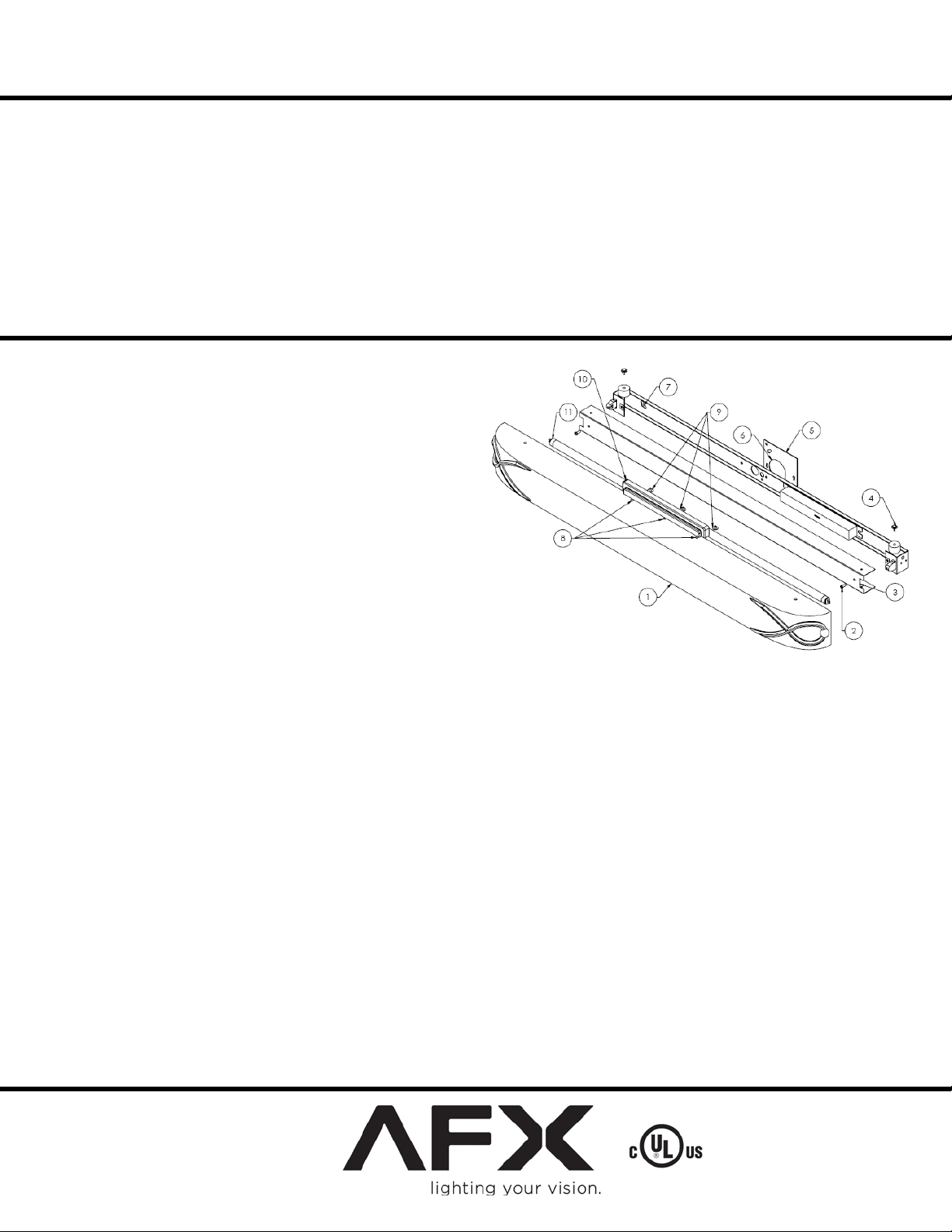
Assembly Inst ru ct i o ns
1. Preparing for installation
A. Disconnect electrical power before installing or servicing any
part of this fixture.
B. Remove all contents from packaging.
C. Remove screws (2) from housing cover (3). Remove cover (3).
D. Attach decorative end caps (10) with screws (9) to upper and
lower diffuser mounting holes (8).
E. Install junction box cover plate (5)(supplied) to junc t ion box
with #8 screws (not provided).
2. Fixture mounting.
A. To locate, hold channel up to the wall with power supply
knockout (6) located over entryway for power supply wires.
Mark the locations of the mounting holes (7) on the wall.
B. If there is a joist, use wood screws (included) to mount the
channel. Where there is no joist to screw into use wall anchors
and screws (not provided) or toggle bolts (not included) of suitable length to mount channel securely to the wall.
Proceed to step C before final mounting.
C. Feed the black and white supply wires, and the green ground wire into the fixture through the open hole (6). At this time you can finish
mounting the channel to the wall.
3. Wiring.
Caution: Make sure power is off at fuse or circuit breaker box. Check power wires for damage or s crapes. If power supply wires are within
three inches of ball as t use wire suitable for at least 90C (194F). Note: Most dwellings built before 1985 have supply wire rated to 60C. Consult
a qualified electrician before installing.
A. This unit will not op er ate properly unless connected to a “grounded” electr ical circuit. Electri cal shock, over heating, low or no light
output, and shortened lamp life can result if proper grounding is not done.
B. Using wire connectors (provided), connect white supply wire to white ballast lead. Connect black hot supply wire to black ballast lead. Do
not mix wires. Pull on each wire to make sure connections are secure. Make certain no bare wires are exposed outside of wire connectors.
C. Instal l cover (3), position cover over channel and replace screws (2).
D. Install appropriate lamp (11) (included) by inserting lamp pins into lamp holder. Rotate into place to seat lamp for proper connection.
4. Diffuser mounting.
A. Mount diffuser (1) over top of channel and secure with thumbscrews (4).
Power to the fixture can now be restored.
Limited Factory Warranty
American Fluorescent Corporation hereby warranty that this fixture is free from defects in materials and workmanship when installed and used under normal operating
conditions for a period of 2 years from date of purcha s e. This warranty covers all component parts and extends only to replacemen t of defective fixture or components;
it does not cover failure due to improper installation, misuse, mishandling or damage incurred in transit.
Model numbers ending in MV are designed for use in a 120277VAC, 60Hz fused circuit; otherwise the fixture is designed for
use in a 110-120VAC, 60Hz fused circuit. Do not use on a dimming
circuit.
To reduce the risk of electrical shock, and to assure proper operation,
this fixture must be adequately grounded. To accomplish proper
grounding, there must b e a s eparate ground wire (green) or bare metal
contact (metal conduit) between this fixture and the ground
connection of your main power supply panel. The green ground
screw location is clearly marked on the fixture housing.
This fixture is intended to be used for general indoor lighting in dry
or damp locations only. Horizontal or vertical mounting.
Page 1 of 1 8060468 rev.2
 Loading...