

Page 1
LED Pendant Series LED Pendant Light
Model: HRP D2 Fixtures
Safety Precautions
Read all safety precautions and installation instructions carefully before
installing or servicing this fixture. Failure to comply with these
instructions could result in potentially fatal electric shock and/or
property damage.
It is recommended that a qualified electrician perform all wiring. This
fixture must be wired in accordance with all national and local electrical
codes.
Do not handle any energized fixture or attempt to energize any fixture
with wet hands or while standing on a wet or damp surface or in water.
Make sure the power source conforms to the requirements of the
fixture. (See labels on fixture housing)
Assembly Instructions
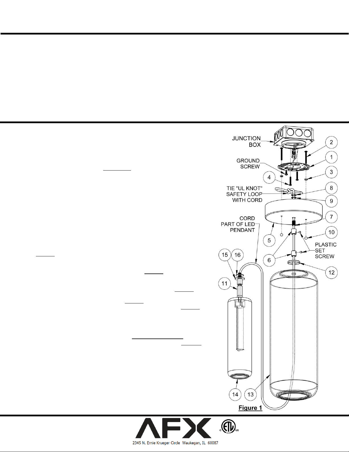
1. Preparing for installation (Figure 1 & 4)
A. Disconnect electrical power before installing or servicing any part of this
fixture.
B. Remove light fixture, hardware, canopy and parts bag from carton.
C. Thread two 1-1/2” long screws (2) into recessed tapped holes in gem bar (1).
Secure these with nut (3) per Figure 1 & 4.
D. Mount gem bar (1), (2) & (3) to junction box with two shorter screws (4).
E. Securely attach green (or green and yellow) wire from supply to green
ground screw in gem bar (1). This unit will not operate properly unless
connected to a “grounded” electrical circuit. Electrical shock,
overheating, low or no light output, and shortened lamp life can result
if proper grounding is not done.
F. With gem bar installed on junction box, take canopy (5) and check that the
holes line up with the screws (2) in the gem bar (as they may become slightly
skewed from tightening or bending of the gem bar). If not, gently push
screws together or pull apart so they line up.
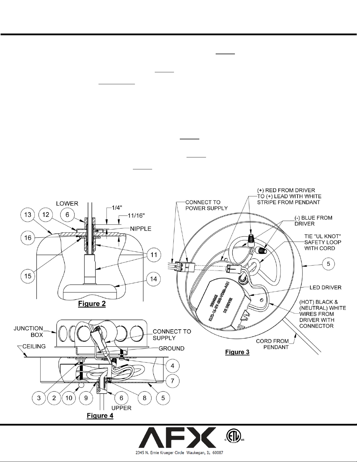
2. Pendant Glass Assembly (Figure 1, 2 & 5)
A. Uncoil cord, part of LED pendant inner glass assembly (14) and thread the
loose end through outer glass (13), cap (12) & lower strain relief (6), per
Figure 1. Remove the tape from the nipple near rubber washer (16). Make
sure threaded washer (15) is snug against the threaded insert of the swivel
(11) and that none of the components are loose. Approx. 11/16” of the
threaded nipple should protrude above (15) per Figure 2. If adjustments are
needed, hand tighten only.
B. Carefully bring inner glass assembly (14) up into the outer glass (13) with
rubber washer (16) against the inside top of outer glass (13), Figure 2.
C. You may set the outer glass on a table to do this step. Hold onto the cord
allowing inner glass (14) to hang, as in Figure 5. With the cap (12) on top of
(13). There should be about 1/4” of threaded nipple above (12), Figure 2.
While holding the cord, thread the lower strain relief (6) onto the nipple.
Make any adjustments so the inner and outer glass are centered. Lift entire
glass assembly by the cord and check that the swivel is straight and the
glass is hanging straight. Additional adjustments may be necessary.
If inner glass is not straight, go to step 6. Swivel Adjustment.
D. Insert the upper strain relief (6), threaded side up onto the cord, Figure 1.
Temporarily secure upper strain relief onto cord at desired height by
tightening the plastic set screw with a small slotted screwdriver (not
included).
E. Feed the cord through the center hole of decorative canopy (5) and move it
down to the upper strain relief (6) position.
3. Fixture Assembly (Figure 3 & 4)
A. Pass the cord through the nipple (7) and thread it into the upper strain relief.
Assemble the lock washer (9) and nut (8) onto the nipple from inside the
canopy. Make sure the nut on the inside of (5) and strain relief are securely
tightened.
B. Check that the pendant is the desired length. To readjust the length of cord
Page 1 of 3 8061055 R0
This fixture is designed for use in a 120-277 VAC, 60Hz fused circuit.
The fixture is compatible with TRIAC (forward-phase or leading-edge) /
ELV (reverse-phase or trailing-edge) and 0-10 V dimmers.
To reduce the risk of electrical shock, and to assure proper operation,
this fixture must be adequately grounded. To accomplish proper
grounding, there must be a separate ground wire (green) or bare metal
contact (metal conduit) between this fixture and the ground connection
of your main power supply panel. The green ground screw location is
clearly marked on the fixture housing.
This fixture is intended for use for general indoor lighting in dry
or damp locations only.
Page 2
LED Pendant Series LED Pendant Light
Model: HRP D2 Fixtures
below the canopy, loosen the plastic set screw in the strain relief with a small slotted screwdriver (not included). With length
established, retighten the plastic set screw.
C. Tie a safety loop, “UL knot” right where the cord comes into the canopy as in Figure 3. Depending on the length, excess cord
may be coiled up inside the canopy, or cut and re-stripped.
D. A strip of double sided adhesive tape is provided to affix the driver to the canopy. Affix to bottom of driver, and driver to inside of
canopy (5) without blocking any holes as shown in Figure 3.
E. Connect two pre-stripped wires from LED pendant cord to the driver with two blue wire nuts as follows:
The (+) from (14) with a thin white stripe to the (+) red wire from driver.
The (-) from (14) to the (-) blue wire from driver.
F. Attach small end of connector (included in parts bag), to black (hot) & white (neutral) driver wires for connecting to supply.
4. Fixture Mounting & Wiring-
All 120VAC wiring must take place inside junction box.
Caution: Make sure power is off at fuse or circuit breaker box. Check power wires for damage or scrapes. If power supply wires
are within three inches of driver use wire suitable for at least 90C (194F). Note: Most dwellings built before 1985 have supply wire
rated to 60C. Consult a qualified electrician before installing.
A. Remove the large end of the power connector from the driver Figure 3 and attach it to the (+) and (–) supply wires up in the
junction box. Make sure the connected supply wires are secure and tucked inside of junction box.
B. Bring the assembled fixture with canopy up to the junction box in the ceiling.
C. Plug the connector from driver into the supply from junction box, Figure 4.
D. Place the canopy (5) onto the two screws (2) from gem bar (1). Insert any wires that may be protruding around the top of the
canopy so it sits flush against the ceiling, Figure 4.
E. Secure with two finial nuts (10) onto the gem bar
screws.
5. Restore power at the fuse or breaker box.
Page 2 of 3 8061055 R0
Page 3

LED Pendant Series LED Pendant Light
Model: HRP D2 Fixtures
Adjusting Swivel (To align inner glass with outer glass)
A. Inspect the top of the outer glass (13) to determine if there
is a taper to the inside top surface as noted in Figure 6, or
if the inner glass (14) is skewed at an angle.
B. Turn the inner glass assembly with swivel (11) so that the
opening is facing the thickest part of the glass. Figure 5, 6
& 7.
C. Move (14) with swivel (11) slightly in the direction of
swivel opening to align inner with outer glass. Figure 6 &
7.
D. Tighten (6) against cap (12) so that the whole assembly is
snug.
E. Tighten the plastic set screw against the cord with a small
slotted screwdriver (not included).
Limited Factory Warranty
AFX Inc. hereby warranty that this fixture is free from defects in materials and workmanship when installed and used under normal operating conditions for a period of 5 years
from date of shipment from factory. This warranty covers all component parts and extends only to replacement of defective fixture or components; it does not cover failure due
to improper installation, misuse, mishandling or damage incurred in transit.
Page 3 of 3 8061055 R0
 Loading...