

AFX GZL432RBMV User Manual
Limited Factory Warranty
failure due to improper installation, misuse, mishandling or damage incurred in transit.
Gizelle Linear Surface Mounted Fluorescent Fixture
Models 432SNR8, 432RBR8, 432SNMV, 432RBMV
Safety Precautions
Read all safety precautions and installatio n ins tr u ct io ns car e f ul ly before
installing or servicing this fixture. Failure to comply with these instructions
could result in potentially fatal electric shock and/or property damage.
It is recommended that all wiring shall be performed by a qualified electrician.
This fixture must be wired in accordance with all national and local electrical
codes.
Do not hand l e any energized fixture or attempt to energize any fixture with
wet hands or while standing on a wet or damp surface or in water.
Make sure that the power source conforms to the requirements of the fixture.
(See labels on fixture housing).
To reduce the risk of electrical shock, and to assure proper operation, this
fixture must be adequately grounded. To accomplish proper grounding, there
must be a sep arate ground wi r e (green) or ba r e metal contac t (metal conduit)
between this fixture and the ground connection of your main power supply
panel. The green ground screw location is clearly marked on the fixture
housing.
This fixture is intended for use for general indoor lighting in dry and damp
locations only.
Assembly Instructions
1. Preparing for installation
A. Disconnect electrical power before installing or servicing this
fixture.
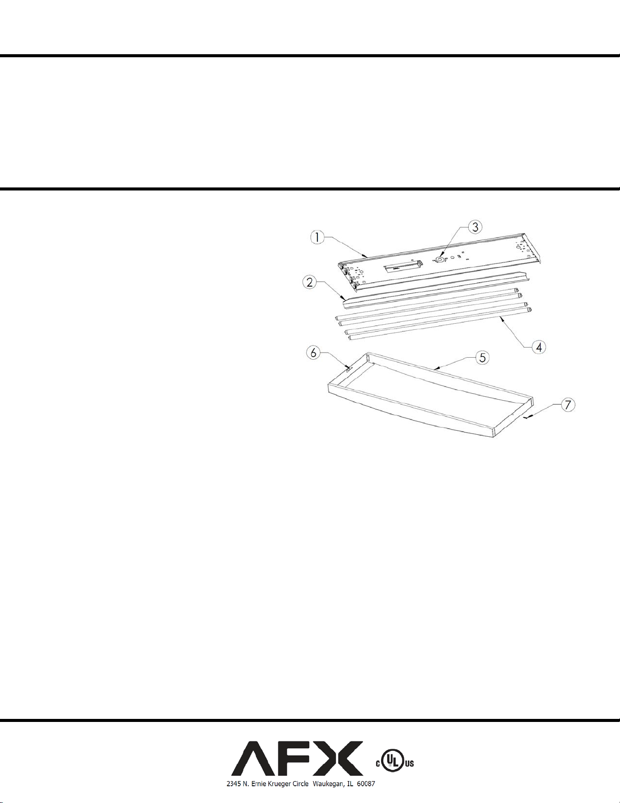
B. Remove center wire-way cove r (2) by squeezing near th e
dimple at each end in the fixture channel (1).
2. Fixture mounting
C. Locate the knockout (3) that best mee ts your m ount ing
requirements and remove it. To remove knockouts it is
recommended to use a blunt object facing away from you to
punch out.
D. Position the fixture channel (1) onto the ceiling and mark all
appropriate mounting locations. You may need someone to
help you hold the fixture up. Take the fixture channel (1)
down and punch a small hole in the ceiling at each of the
locations you have marked using a nail or an awl to see if ther e
is a wood joist above that you can mount the fixture to. Where
there is a wood joist, use a suitable wood screw (not included)
to mount the fixture. Where there is no joist to screw into, a
3/16” toggle bolt (not included) must be used to mount the
fixture channel securely to the ceiling. Secure fixture channel to
ceiling.
3. Wiring
Caution: Make sure power is off at fuse or circuit breaker box. Check power wires for damage or scrapes. If power supply wires are within three
inches of ballast use wire suitable for at least 90C (194F). Note: Most dwellings built before 1985 have supply wire rated to 60C. Consult a qualified
electrician before installing.
E. This unit will not operate properly unless connected to a “grounded” electr ical circuit. Electrical s hock, over heating, low or no li ght output, and
shortened lamp life can result if proper grounding is not done. Feed the green (or green and yellow) wire through knockout (3) and securely
attach to provided green ground screw. Feed the white and black wires through knockout (3).
F. For standard models: Using wire nuts (not provided), connect white supply wire to white ballast lead. Connect black hot supply wire to black
ballast lead. Pull on each wire lead to make sure co nnection is secure. Make certain no bare wires are exposed outside of wire nuts.
G. For models pre-wired to luminaire disconnect: Using luminaire disconnect (provided), insert white supply wire into the hole across from white
ballast lead. Insert black hot supply wire into hole acr oss from black ballast lead. Do not mix wires.
H. Replace ballast cover by placing o ne edge of ballast cover (2) into dimples, swing upward, press cover allowing second edge to catch second set
of dimples and lock in place. Make sure n o wires become crimped between cover and fixture.
I. Install appropriate lamps (4) (not included): Insert linear lamp pins into lamp holder. Rotate into place to seat lamp for proper connection. For
bent shape U-lamps; align bend in lamp into lamp holders and snap lamp pins into sockets. (not shown)
4. Frame mounting
J. To prevent light leaks between the fixture and ceiling, attach foam gasket (included – not pictured) to frame (5) using the supplied instructions.
K. Maneuver the tab (6) between channel (1) and the ceiling surface. Swing the frame (5) up to ceiling. Secure the opposite end of the frame (6) to
the channel (1) using the screw (7) provided. Be careful not to over tighten.
L. Restore power at fuse or circuit breaker box.
AFX inc. hereby warranty that this fi xture is free from defects in materials and workmanship when installed and used under normal operating conditions for a period
of 2 years from date of purc hase. This warranty covers all component parts and extends only to replacement of defective fixture or components; it does not cover
8060552 rev.3
 Loading...