

Page 1
EXL SERIES
Line Voltage Xenon Undercabinet Fixture
Models 120, 220, 320, & 420
Safety Precautions
Read all safety precautions and installation instructions carefully
before installing or servicing this fixture. Failure to comply with
these instructions could result in potentially fatal electric shock
and/or property damage.
It is recommended that a qualified electrician perform all wiring. This
fixture must be wired in accordance with all national and local
electrical codes.
Do not handle an energized fixture or attempt to energize any fixture
with wet hands or while standing on a wet or damp surface or in
water.
Make sure that the power source conforms to the requirements of the
fixture. (See labels on fixture housing).
To reduce the risk of electrical shock, and to assure proper operation,
this fixture must be adequately grounded.
Assembly Instructions
Lighted lamp is HOT!
Bulb gets HOT quickly! Do not touch hot lens or enclosure.
Do not touch bare lamp with your bare skin. Oils from
12
FOR Model No: EXL Series:
Do not interconnect more than 560 watts
Use only a 120V/20W or smaller Xenon bulb (bi-pin Base Only).
This fixture is to be used for general indoor lighting in dry locations
only.
Dimming: This unit can be dimmed with a standard incandescent
wall dimmer.
Interconnectable / Cord or Direct Wire
your skin may damage the lamp when it heats up.
-inch minimum spacing distance from glass required
for all objects located under fixture.
Example: 560 watts (28 lamps x 20w)
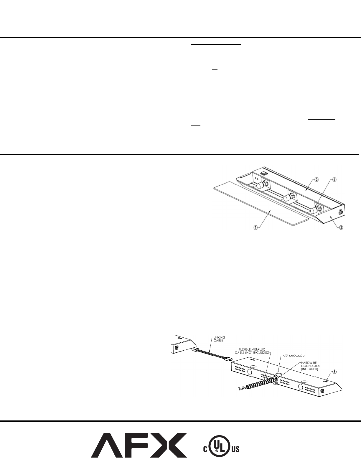
1. Preparation for Installation
A. Disconnect electrical power before installing or servicing any part of this
fixture.
B. Place fixture on a clean flat surface with lens (1) towards you.
C. Remove glass lens by lightly pressing down on both ends while sliding it
directly away from the fixture.
D. If lamps are not
use. (DO NOT TOUCH LAMP glass with bare hands, oils from your skin
may damage lamp when it heats up.)
E. Determine input power method (Hardwire, Cord or Link) below and follow
corresponding directions.
2.
Cord to Outlet Installation
(Skip this step if using Hardwire or Link to Fixture Installation)
A. Fixture must be mounted within 5’ of an outlet. Locate
B. Connect Cord to fixture by snapping the quick connect end of the cord to the corresponding connector in the end of the
fixture marked “IN”. The cord will only connect to the “IN” connector so make sure you have the right connector identified.
Do not force the connection, it should snap in easily.
C. Follow the directions for Mounting and Lamping below.
D. Once Mounting and Lamping ar
3.
Hardwire Installation Preparation
(Skip this step if using Cord to Outlet or Link to Fixture Installation to Power Unit)
A. Discard Cord if Hardwire Installation is used.
B. Open cover by squeezing to disengage it from the
retaining tabs of the housing. Rotate it 90º.
C. Remove appropriate 7/8” diameter knockout for supply
wiring entry.
D.
Determine appropriate connector:
i)
NM-Romex - A non-metallic push-on connector is
included for use.
ii) Flexible conduit (BX)– A push-on connector
(shown) is included for use.
E. Insert BX cable (not included) or Romex (not included)
through appropriate connector. Feed appropriate supply
wires (1 black wire, 1 white wire and a ground wire)
through open 7/8” hole in the housing and push connector into hole until it snaps in place.
F. Follow the di
Page 1 of 2
installed and packed separately, carefully put aside for later
the 5’ power cord included in the box.
e completed, plug the cord into the outlet.
rections below for Mounting then proceed to Hardwire Installation Completion.
8060525 R7
Page 2
EXL SERIES
Line Voltage Xenon Undercabinet Fixture
Models 120, 220, 320, & 420
4.
Link to Fixture Installation
Interconnectable / Cord or Direct Wire
(Skip this step if using Hardwire or Cord to Outlet Installation.)
A. First fixture can be Corded or Hardwired
B. Second fixture must be located within 12” of first fixture.
C. A Maximum of 560 Total Watts can be Linked.
D. Make sure power is off to all fixtures.
E. Connect the Linking cord to the “Out” connector in the first fixture and to the “In” connector of the second fixture. The
connectors only fit one way. Do not force the connections they should snap in easily.
F. Follow directions in Mounting and Lamping Section.
G. Once Mounting and Lamping are completed, energize first fixture.
Injury to persons and damage to the mounting surface may result if the fixture or mounting hardware is pulled from the mounting
Note:
location. To reduce the possibility of such injury, be sure to mount the fixture only on a surface that is mechanically, structurally sound.
5. Mounting
A. Using keyhole slots for mounting the fixture. Position the housing in location intended for mounting. Mark mounting screw location by
keyhole slots as guides. Remove housing and partially install both #8 x ½” wood screws (provided) in the marked positions. Mount
using
the housing to desired surface by placing the keyhole slots over mounting screw and shifting housing to one side to secure in position.
Tighten mounting screws.
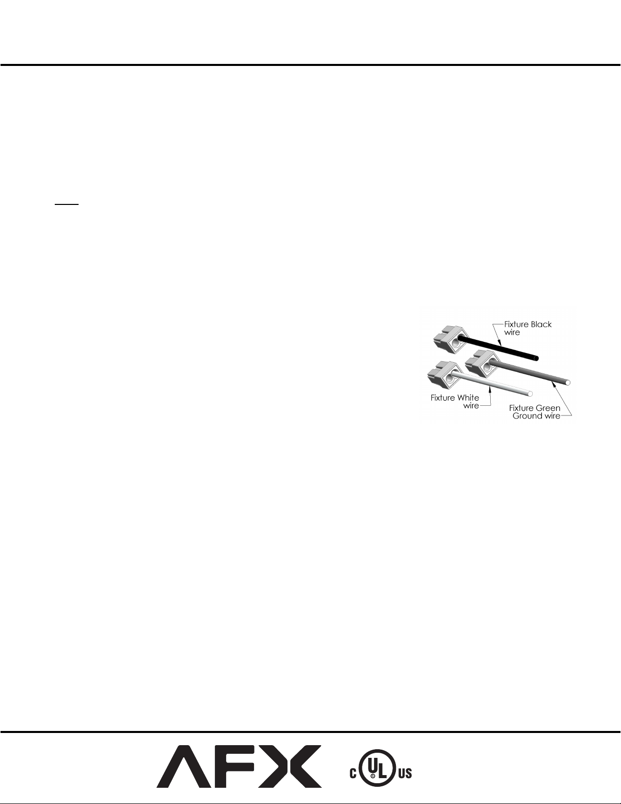
6. Hardwiring Installation Completion
A. Connect the Green ground input supply wire to the fixture Green ground wire. Do this by
inserting it into the open hole in the push-in wire connector (included) that is attached to the
Green ground wire in the fixture.
B. Connect the White input supply wire to the fixture White wire. Do this by inserting it into
the open hole in the push-in wire connector (included) that is attached to the White wire in
the fixture.
C. Connect the Black input supply wire to the fixture Black wire. Do this b
the open hole in the push-in wire connector (included) that is attached to the Black wire in
the fixture. Do not mix wires or change polarity.
D. Pull on each wire lead to make sure connections are secure. Make certain no bare wires are
exposed outside of the wire connectors.
E. To close cover- Carefully arrange wires so they do not get pinched and rotate cover against
channel. Secur
F. Proceed to Lamping Instructions below.
e cover under housing lances.
y inserting it into
7. Lamping
DO NOT TOUCH BARE LAMPS WITH BARE HANDS. Oils from your Skin may damage the lamp when it heats up.
A. Remove lamp from box. Hold the lamp by the Pins or with the use of a protective plastic cover (a glove or a plastic bag work well).
B. Install lamps by pushing straight into sockets. Adjust lamp(s) as needed to not touch lens.
Replace glass lens by sliding it back into housing until it fully seats within the housing
C.
DO NOT LOOK DIRECTLY AT LIGHTED LAMP.
8. Lamp Removal
A. Allow lamp to cool before handling.
B. Remove the lamp by grasping and pulling straight out from the lamp socket.
C. See the label on the fixture for replacement lamp type information. Maximum 20 watts (BI-PIN base) 120volt Xenon lamp.
Limited Factory Warranty
AFX warrants this fixture is free from defects in materials and workmanship when installed and used under normal operating conditions
for a period of 2 years from date of purchase. This warranty covers all component parts and extends only to replacement of defective fixture
or components; it does not cover failure due to improper installation, misuse, mishandling or damage incurred in transi
Page 2 of 2
t.
8060525 R7
 Loading...