

Page 1
Cortez Sconce Fluorescent Fixtures
Models: CZS118MV, CZS124MV
Safety Precautions
Read all safety precautions and installation instructions carefully
before installing or servicing this fixture. Failure to comply with
these instructions could result in potentially fatal electric shock
and/or property damage.
It is recommended that all wiring be performed by a qualified
electrician. This fixture must be wired in accordance with all national
and local electrical codes.
Do not handle any energized fixture or attempt to energize any
fixture with wet hands or while standing on a wet or damp surface or
in water.
Assembly Instructions
1. Preparing for installation
A. Disconnect electrical power before installing or servicing any part of
this fixture.
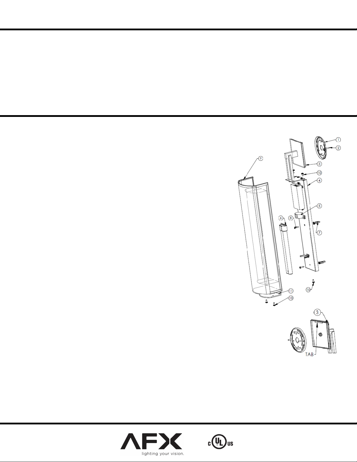
B. Remove fixture from carton; remove backpan assembly (4) and diffuser
assembly (9).
All wiring must take place inside junction box. Caution: Make sure
power is off at fuse or circuit breaker box. Check power wires for damage or
scrapes. If power supply wires are within three inches of ballast use wire
suitable for at least 90C (194F). Note: Most dwellings built before 1985
have supply wire rated to 60C. Consult a qualified electrician before
installing. This unit will not operate properly unless connected to a
“grounded” electrical circuit. Electrical shock, over heating, low or no light
output, and shortened lamp life can result if proper grounding is not done.
Securely attach green (or green and yellow) wire to ground supply wire.
Make sure that the power source conforms to the requirements of the
fixture. (See labels on fixture housing). Model numbers ending in
MV are designed for use in a 120-277VAC, 60Hz fused circuit (Do
not use on a dimming circuit).
To reduce the risk of electrical shock, and to assure proper operation,
this fixture must be adequately grounded. To accomplish proper
grounding, there must be a separate ground wire (green) or bare metal
contact (metal conduit) between this fixture and the ground
connection of your main power supply panel.
This fixture is intended to be used for general indoor lighting in dry
or damp locations only.
A. For wiring ballast power leads and power supply wires use Ballast
Disconnect Instructions (included).
B. Tuck all connections neatly into junction box.
2. Mounting
A. Install circular gem bar (1) (included) on junction box (not included) by
securing it with two screws (2) (included).
B. Mark the locations of the two backpan mounting holes located 13” and
20.5” relatively to the center of the junction box. (Or use
backpan/bracket assembly as a template, hook up the assembly on the
gem bar by using top plate (3) tab -see picture below).
C. If installed on the dry wall, drill two .25” dia holes 1 1/2” deep. Install
two anchors (7) (included) on the wall.
D. Hook up the fixture on the gem bar (1) by using top mounting (3) tab.
E. Secure the backpanel assembly (4) on the wall by with two screws (8) (included).
3. Lamps
A. Install the compact fluorescent lamp (6) (not included) into the socket (5).
4. Diffuser mounting
A. Install bottom diffuser (11) on the shade assembly (9) by securing it with two screws (10).
B. Align diffuser (9) mounting holes with the two backpan (4) mounting holes on the top and one hole on the bottom.
C. Secure diffuser with three screws (10).
5. Power to the fixture can now be restored.
Limited Factory Warranty
American Fluorescent Corporation hereby warranty that this fixture is free from defects in materials and workmanship when installed and used under
normal operating conditions for a period of 2 years from date of shipment from factory. This warranty covers all component parts and extends
only to replacement of defective fixture or components; it does not cover failure due to improper installation, misuse, mishandling or damage incurred in
transit.
Page 1 of 1 8060720 R2
 Loading...