

Page 1
CMF, C2F, CSF Series Fluorescent Cloud Fixture
C2F 4-PIN CFQ
Model; 218, 213, 226, 318, 326, 2022, 2032, 205 4, 2072
Safety Precautions
Read all safety precautions and installation instructions
carefully before installing or servicing this fixture. Failure to
comply with these instructions c ould result in potentially fatal
electric shock and/or property damage.
It is recommended that all wiring be performed by a qualified
electrician. This fixture must be wired in accordance with all
national and local electrical codes.
Do not handle any energized fixture or attempt to energize any
fixture with wet ha nd s or whil e stand ing on a wet or damp
surface or in water.
Make sure that the power source conforms to the requirements
of the fixture (see labe l s on fixture housing).
To reduce the risk of electrical shock, and to assure proper
operation, this fixture must be adequately grounded. T o
accomplish proper grounding, there must be a separate ground
wire (green) or bare metal contact (metal conduit) between
this fixture and the ground connection of your main power
supply panel. The green ground screw location is clearly
marked on the fixture housing.
This fixture is intended to be used for general ind oor lighting
in dry or damp locations only.
Assembly Inst ruc t i on s
1. Preparing for installation
A. Disconnect electrical power before installing or servicing any part of this
fixture.
B. Remove fixture and hardware bag from carton.
2. Wiring
All wiring must take place inside ju nction box. Caution: Make sure power is off
at fuse or circuit breaker box. Check power wires for damage or scrapes. If power
supply wires are within three inches of ballast use wire suitable for at least 90C
(194F). Note: Most dwellings built before 1985 have supply wire rated to 60C.
Consult a qualified electrician before installing.
A. This unit will not operate properly unless connected to a “grounded” electrical
circuit. Electrical shock, overhea ting, low or no light output, and shortened lamp
life can result if prope r grounding i s not done. Securely attach green (or green
and yellow) wire to ground supply wire.
B. Using wire connectors (not provided), connect white supply wire to white
ballast lead. Connect black hot supply wire to black ballast lead. Do not mix wires. Pull on each wire lead to make sure
connections are secure. Make certain no bare wires are exposed outside of wire connectors. Note: fixtures with uni ve r sal vol ta ge
power supplies are pre-wired with a disconnect. Refer to the included guide for using the disconnect.
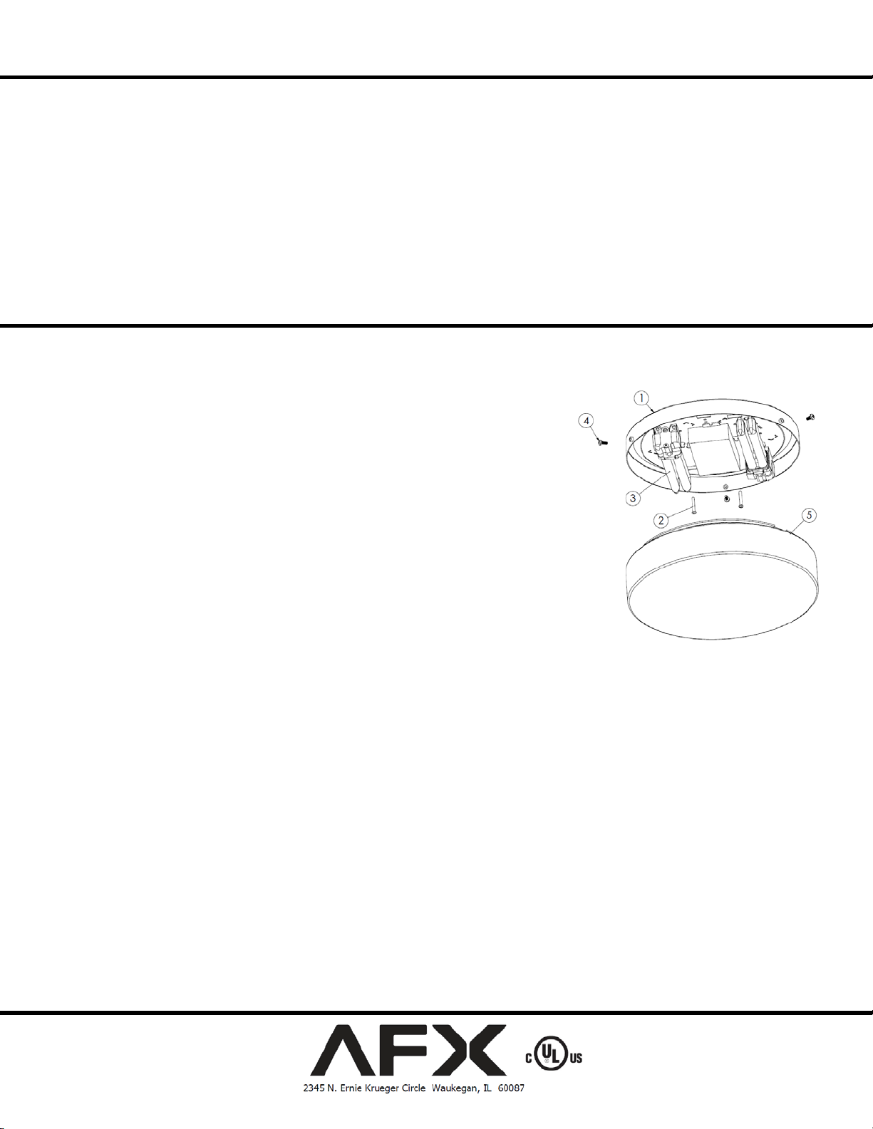
3. Mounting
A. Mount fixture housing (1) to junction box with the two #8-32 x 7/8” screws (2 - provided) through keyhole slots.
4. Lamps
A. Compact – 4-pin (3 - Not provided) insert lamp pins into lamp holder and press until lamp snaps in place.
B. GU24 – (No t shown) insert lamp pins into lamp holder and rotate until lamp snaps in place.
C. Circle line – (Not shown) insert lamp pins into lamp holder and press until lamp snaps in place.
5. Diffuser mounting
A. Thread the three thumb screws (4) partially into the thre e threaded inserts in the fixture housin g ( 1).
B. The ro und white plastic diffuser (5) has three notches in the outer flange. Align these notches with the three t humb screws (4 )
on the fixtur e housing (1) and push the diffuser up against the fi xture housi ng. Rotate the diffuser slightly and hand tighten the
three thumb screws (4) equally on all sides. Do not over tighten.
LAMPING SHOWN
Power to the fixture can now be restored
6.
Limited Factory Warranty
AFX Inc. hereby warranty that this fixture is free from defects in materials and workmanship when installed and used under normal operating conditions for a period of 2
years from date of purch ase. This warranty covers all component parts and extends only to replacement of defect ive fixture or components; it does not cover failure due t o
improper installation, misuse, mishandling or damage incurred in transit.
Page 1 of 1 8060755 Rev.1
 Loading...