

AFX CHL432WWR8 User Manual
CHL SERIES Chesterfield
1 of 2
8060145 R1
Model 432 Ceiling Mounted Fixture
Safety Precautions
Read all safety precautions and installation instructions carefully
before installing or servicing this fixture. Failure to comply with
these instructions could result in potentially fatal electric shock
and/or property damage.
It is recommended that a qualified electrician perform all wiring. This
fixture must be wired in accordance with all national and local
electrical codes.
Do not handle any energized fixture or attempt to energize any
fixture with wet hands or while standing on a wet or damp surface or
in water.
Tools Required: Phillips Screwdriver, Adjustable Wrench & Pliers.
Hardware Required: Appropriate mounting hardware
Parts Inventory (Items to be Assembled)
Packed inside the carton
1) 1 Channel Sub-assembly with 1 knockdown arm/rail sub-
assembly (3) (Cut only the black plastic ties on the flat carton)
Note: Same as Fig 1 after assembled
2) 1 Rail 4ft long (12) (Cut only the black plastic ties)
3) 3 Ironwork arm with hardware: (7), (8), (16), (17) (Fig 1a)
4) 1 Wood frame (26), 1 Plastic lens (27)
5) Plate / Canopy / Mounting Parts: 10 items (13), (18), (19) (20),
(21), (22), (23), (24), (25) and (26) (see Fig 4a, Fig 5 and Fig 6)
6) Hardware parts: Three wire connectors
This fixture is designed for use in a 110-120VAC, 60Hz circuit. Do
not use on a dimming circuit, unless unit is provided with appropriate
dimming ballast.
To reduce the risk of electrical shock, and to assure proper operation,
this fixture must be adequately grounded. To accomplish proper
grounding, there must be a separate ground wire (green) or bare metal
contact (metal conduit) between this fixture and the ground
connection of your main power supply panel. The green ground
screw location is clearly marked on the fixture housing.
This fixture is intended to be used for dry indoor, lighting locations.
Assembly Instructions
1. Preparing for installation
A. Consult a local licensed electrician or electrical contractor about installing the fixture if
you are not sure about installation.
B. Select a suitable dry location (use for indoors only). Make sure mounting surface is
capable of supporting the 30lbs weight of the fixture.
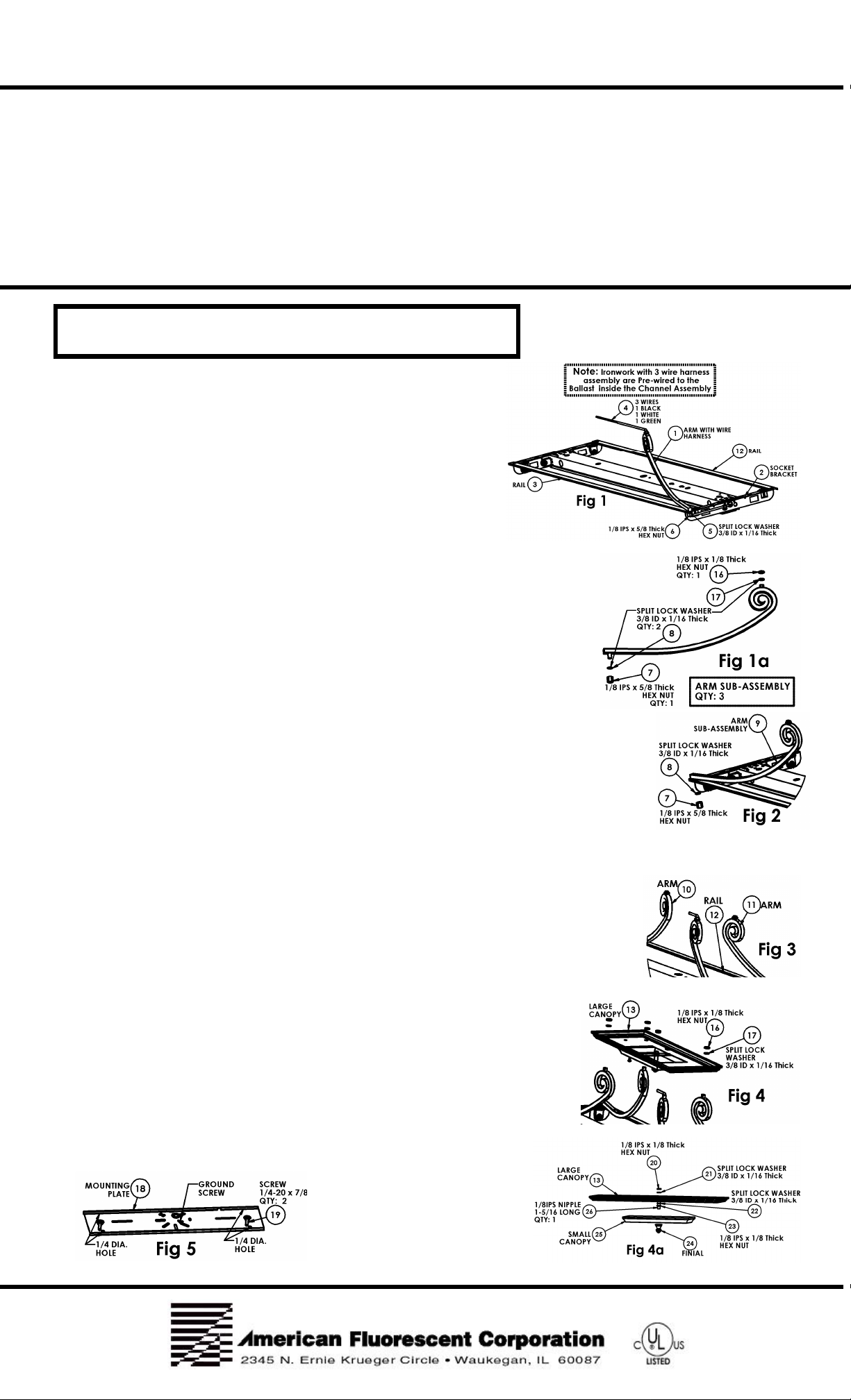
2. Assembling Fixture (Use Fig 1 to Fig 8).
A. Flip channel sub-assembly as shown in Fig 1. Cut the tie wrap where the corded arm is
dangling.
B. Now assemble the knockdown pre-assembled channel sub-assembly by aligning the
parts together as they are shown in Fig 1 and fasten the hex nut on to the arm.
C. The next step is to assemble the arm sub-assembly (Fig 1a) on to rail (3) and to socket bracket
(9), use the provided split lock washer (8) and hex nut (7) to lock and secure the arm.
Note: Repeat these procedures two times to install the remaining arm sub-assembly (10) and (11)
with the other rail (12) as it shown in Fig 3.
D. Next to assemble is the large canopy (13) with the 1-5/16 nipple (26) and secure it with parts:
(20), (21), (22), (23) as shown in Fig 4a.
Note: The small canopy (25) and the finial (24) will be installed after the wiring of the fixture is completed.
E. Now install the sub-assembly that you just built to the 4 arm assemblies as they are shown in Fig 4. To install the canopy,
first remove hardware (16), (17) on the arms and place the large canopy (13) and put back the
hardware and tighten to secure mechanically.
3. Installing Fixture Mounting Plate (Use Fig 5) (Fixture Total Load Weight: 30 lbs)
A. Before you install the mounting plate (18) that is shown in Fig 6, make sure to knockout the
necessary holes on the plate and route the in-line power supply wires from the outlet box. Now
install the plate on the outlet box. Note: To rgidly secures the plate we recommend to use an
outlet box and extra support hardware ¼ trade size screws (not included) or 1/4 toggle bolts
(not included) at the ¼ diameter hole locations as shown in Fig 5.
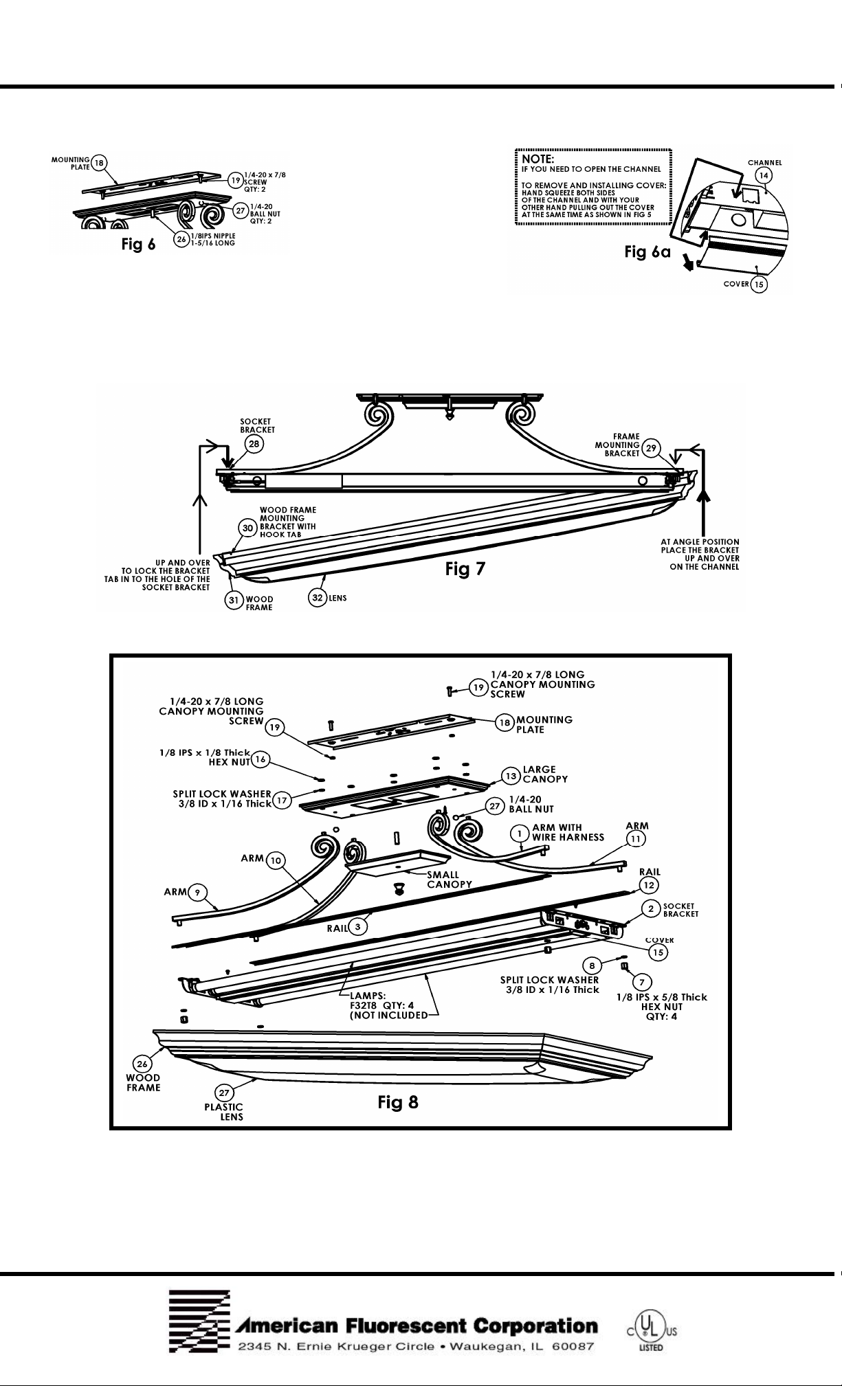
4. To Install Fixture / Canopy to Plate (Use Fig 6)
A. Align the 2 holes on the canopy to the plate ¼-20 studs (19) and fasten it with the
two ¼-20 ball nuts (27). Note: For wiring purposes, make sure you route the end of
the wire harness (4) near the rectangular holes of the large canopy (13).
5. Wiring the Fixture (Use Fig 4a and Fig 6)
A. Use the wire connector provided to connect the in-line black wire to the black wire
of the arm harness (4), use the wire connector provided to connect the in-line white
wire to the white wire of the arm harness and the remaining green wire to the green
wire of the arm harness.
B. Now install the small canopy (25) and fasten it with the finial (24) (Fig4a).
CHL SERIES Chesterfield
2 of 2
8060145 R1
Model 432 Ceiling Mounted Fixture
6. If Required to Remove the Cover from the Channel (Use Fig 6a)
A. Follow instructions as it shown in Fig 6a.
7. Installing the Wood Frame on to the Ironwork Arm Assembly (Use Fig 7).
A. Tip the wood frame as it shown in Fig 7 and make sure the wood frame bracket (29) is on the top of the channel then swing
the other end of the frame Up and Over and move it forward about 1 inch until the hook tab of the bracket (30) is in the hole.
Note: Make sure both of the wood frame bracket tabs (29), (30) are in the large hole of the socket bracket (2), (28).
8. Exploded View
Limited Factory Warranty
American Fluorescent Corporation hereby warranty that this fixture is free from defects in materials and workmanship when installed and used under
normal operating conditions for a period of 2 years from date of purchase from factory. This warranty covers all component parts and extends only to
replacement of defective fixture or components; it does not cover failure due to improper installation, misuse, mishandling or damage incurred in
transit.
 Loading...