

Page 1
LED Indoor Luminaires
Ceiling Mount – Pendant
120VAC / 60Hz
Page 1 of 1 8061535 R0
Model #: STHP0136LAJD1xx
STHP0146LAJD1xx
Limited Factory Warranty
AFX Inc. hereby warrants that this fixture is free from defects in materials and workmanship when installed and used under normal operating conditions for a period of 5 years
from date of purchase. This warranty covers all component parts and extends only to replacement of defective fixture or components; it does not cover failure due to improper
installation, misuse, mishandling or damage incurred in transit.
Safety Precautions
Read all safety precautions and installation instructions carefully before installing or servicing this fixture. Failure to comply with these instructions could result in potentially fatal
electric shock and/or property damage.
It is recommended that a qualified electrician perform all wiring. This fixture must be wired in accordance with all national and local electrical codes.
Do not handle any energized fixture or attempt to energize any fixture with wet hands or while standing on a wet or damp surface or in water.
This fixture is designed for use in a 120VAC / 60Hz circuit. This fixture is compatible with a TRIAC (forward-phase or leading-edge) / ELV (reverse-phase or trailing-edge) dimmer.
Make sure that the power source conforms to the requirements of the fixture. (See labels on the fixture housing).
To reduce the risk of electrical shock, and to assure proper operation, this fixture must be adequately grounded. To accomplish proper grounding, there must be a separate ground
wire (green) contact between this fixture and the ground connection of your main power supply panel.
This fixture is intended to be used for general indoor lighting in dry or damp locations.
Disclaimer
Changes or modifications not expressly approved by the party responsible for compliance could void the user’s authority to operate the equipment. NOTE: This equipment has been
tested and found to comply with the limits for a Class B digital device, pursuant to Part 15 of the FCC Rules and Canadian ICES-005 (B) / NMB-005 (B). These limits are designed to
provide reasonable protection against harmful interference in a residential installation. This equipment generates, uses, and can radiate radio frequency energy and, if not installed
and used in accordance with the instructions, may cause harmful interference to radio communications. However, there is no guarantee that interference will not occur in a particular
installation. If this equipment does cause harmful interference to radio or television reception, which can be determined by turning the equipment off and on, the user is encouraged
to try to correct the interference by one or more of the following measures:
• Reorient or relocate the receiver antenna.
• Increase the separation between the equipment and receiver.
• Connect the equipment into an outlet on a circuit different from that to which the receiver is connected.
• Consult with the dealer or an experienced radio/TV technician for help.
Any modifications to this fixture may void the warranty and interfere with the safe operation of the luminaire.
Operation is subject to the following two conditions: (1) this device may not cause interference, and (2) this device must accept any interference, including interference that may
cause undesired operation of the device.
Assembly Instructions
Step 1 – Preparing for installation
A. Disconnect electrical power at fuse or circuit breaker box before installing or servicing any part of this fixture.
B. Carefully remove the fixture from the carton, remove components from hardware kit.
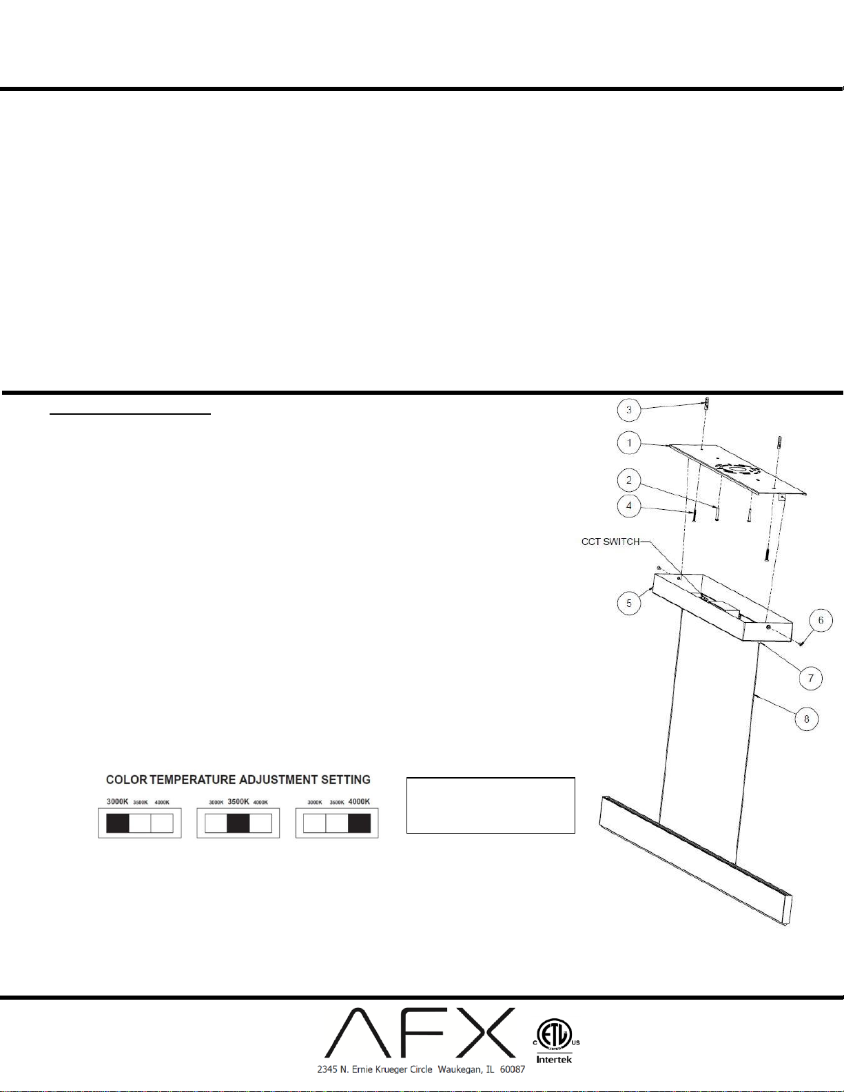
C. Remove mounting bracket (1) from the fixture (5) by removing two finials (6).
D. Install mounting bracket (1) to the junction box (not included) using two screws (2) to secure it. For additional support,
use pencil to mark at the slots for screws (4 – not included). Take the mounting bracket (1) down and drill a small hole
in the ceiling at each of the marked locations to see if there is a wall stud. Where there is a wall stud, use a wood
screw (4) to mount the bracket. Where there is no stud to screw into, drill a larger hole for a drywall anchor (3 – not
included). Reinstall the mounting bracket with four screws to secure it.
Wiring – All wiring must take place inside junction box (not included)
Caution: Make sure power is off at fuse or circuit breaker box. Check power wires for damage or scrapes. If power
supply wires are within three inches of the LED driver, use wire suitable for at least 90°C (194°F). Note: Most
dwellings built before 1985 have supply wire rated to 60°C. Consult a qualified electrician to ensure correct branch
circuit conductor before installing.
Step 2 – Wiring fixture
A. Make all wire connections to appropriate wire. Secure with wire nuts (provided).
B. Connect the green wire from the fixture to the supply power source ground wire.
C. For none dimming fixture. Connect the white wire from the fixture to the white (N) wire from supply power source.
Connect the black wire from the fixture to the black (L) wire from supply power source.
D. For TRIAC dimming. Connect the white wire from the fixture to corresponding white (N) wire in accordance with the
dimmer manufacturer instructions. Connect the black wire from the fixture to the corresponding control line (L) wire in
accordance with the dimmer manufacturer instructions.
E. Do not mix wires. Pull on each wire lead to make sure connections are secure. Make certain no bare wires are
exposed outside of wire connectors. Tuck all connections neatly into the junction box.
Step 3 – Color changing temperature adjustment, CCT (if desired)
A. Adjust CCT switch inside the canopy to the desired color temperature of 3000K, 3500K or 4000K. Note: Fixture is
preset to 3000K from factory.
Step 4 – Mounting
A. Install fixture (5) by aligning side holes over the mounting bracket (1) then using two screws (6) to secure it.
B. Adjust fixture height by depressing on the strain relief (7) then push excess cord (8) inside the canopy until desire
height is achieved. Repeat same procedure on the other cord until fixture is level. Note: fixture is provided with 72”
cord.
Step 5 – Restore power at fuse or circuit breaker box
View shown for reference
only. Individual models may
vary.
 Loading...