

Page 1
ARV Series Aria Fluorescent Vanity Fixture
Models 124, 139 and 154
Safety Precautions
Read all safety precautions and installation instructions carefully
before installing or servicing this fixture. Failure to comply with
these instructions could result in potentially fatal electric shock
and/or property damage.
It is recommended that a qualified electrician perform all wiring. This
fixture must be wired in accordance with all national and local
electrical codes.
Do not handle any energized fixture or attempt to energize any
fixture with wet hands or while standing on a wet or damp surface or
in water.
Assembly Instructions
1. Preparing for installation
A. Disconnect electrical power before installing or servicing any part of this fixture.
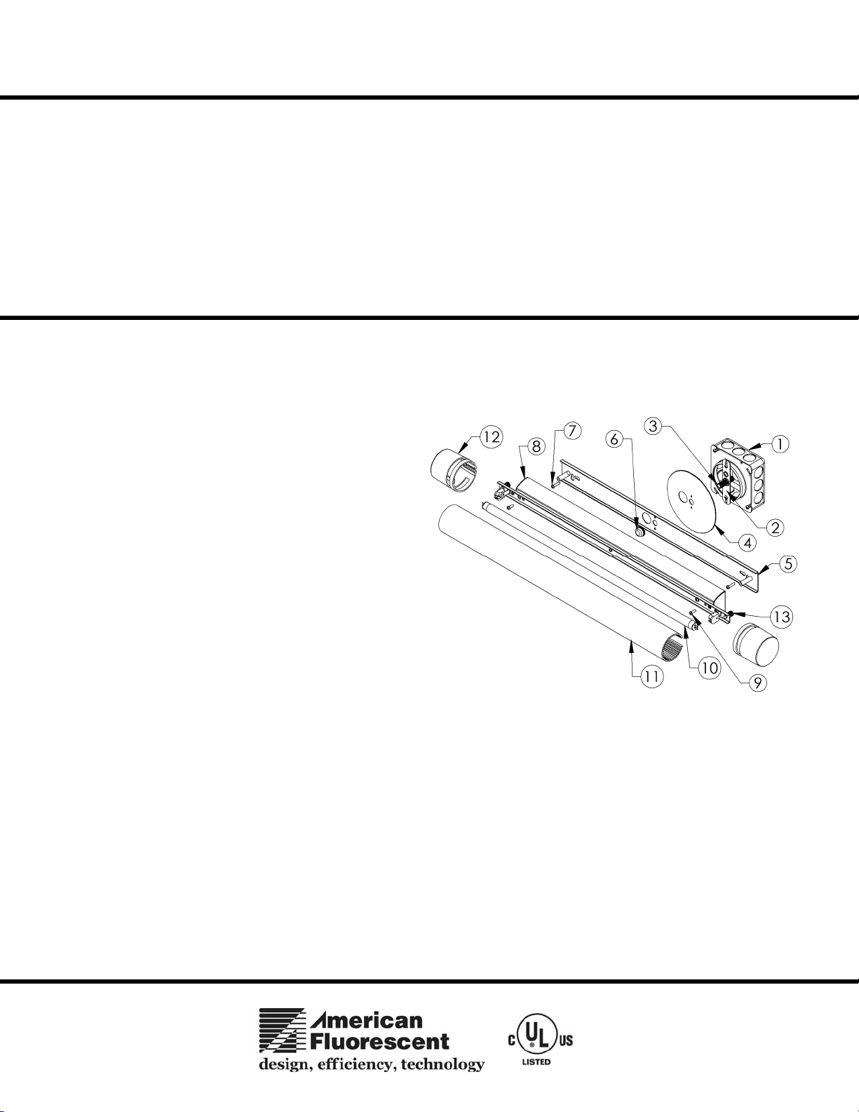
B. Secure the gem bar (2) to junction box (1) (not supplied) with appropriate screws (not supplied). Install the 1 ¼” stem (3) into
the gem bar. Use the lock nut to secure threaded rod at the proper length.
2.
Wiring and Fixture Mounting
Caution: Make sure power is off at fuse or circuit breaker box.
If power supply wires are within three inches of ballast use wire
suitable for at least 90C (194F). Note: Most dwellings built
before 1985 have supply wire rated to 60C. Consult a qualified
electrician before installing.
A. This unit will not operate properly unless connected to
a “grounded” electrical circuit. Securely attach green
(or green and yellow) wire to green ground screw on
gem bar with provided hardware.
B. If using Romex, snap an appropriate fitting (not
supplied) into the wall channel opening and feed
through. If hard-wired, attach appropriate conduit
fitting (not supplied). Using wire connectors
(provided), connect white supply wire to white ballast
lead. Connect black hot supply wire to black ballast
lead. Pull on each wire lead to make sure connections
are secure.
C. If using a junction box, attach wall channel (5) to round coverplate (4) with two screws and nuts provided. Feed supply wires
through large opening in wall channel and make wire connections as described in step 2B. Mount over the 1-1/4” stem and
secure in place with knob (6). (Note: Adjust length of threaded rod to create a secure fit.) Additionally secure the wall
channel at end keyslots with two mounting screws (7) and anchors (not provided ). If not securing to a junction box, hang the
wall channel in desired location using end keyslots with mounting screws provided and anchors (not provided).
D. Mount fixture chassis (8) over wall channel standoffs and secure with two screws (9).
E. Lamps - Install appropriate lamp (10) by inserting lamp pins into lampholder, press and rotate until lamp snaps into place. If
mounting vertically, insert lamp with label end up.
4. Diffuser installation
A. Place diffuser (11) over lamp and center it. Slide cast ends (12) over fixture ends and secure with captive thumbscrews (13).
B. Restore power at fuse or circuit breaker box.
Limited Factory Warranty
American Fluorescent Corporation hereby warranty that this fixture is free from defects in materials and workmanship when installed and used under normal operating
conditions for a period of 2 years from date of purchase. This warranty covers all component parts and extends only to replacement of defective fixture or components;
it does not cover failure due to improper installation, misuse, mishandling or damage incurred in transit.
This fixture is designed for use in a 120 VAC, 60Hz fused circuit. Do
not use on a dimming circuit.
To reduce the risk of electrical shock, and to assure proper operation,
this fixture must be adequately grounded. To accomplish proper
grounding, there must be a separate ground wire (green) or bare metal
contact (metal conduit) between this fixture and the ground
connection of your main power supply panel. The green ground
screw location is clearly marked on the fixture housing.
This fixture is intended to be used for general indoor lighting
in dry or damp locations only.
Page 1 of 1 8060124 Rev.1
 Loading...