

Page 1
MODEL #ADLF432SNR8
MODEL #ADLF432RBR8
4.5 FT. 4-LIGHT
FLUORESCENT FIXTURE
Questions, problems, missing parts? Before returning to your
retailer, call our customer service department at 1-800-873-2326,
8 a.m. - 4:30 p.m.,EST, Monday - Friday
Page 2
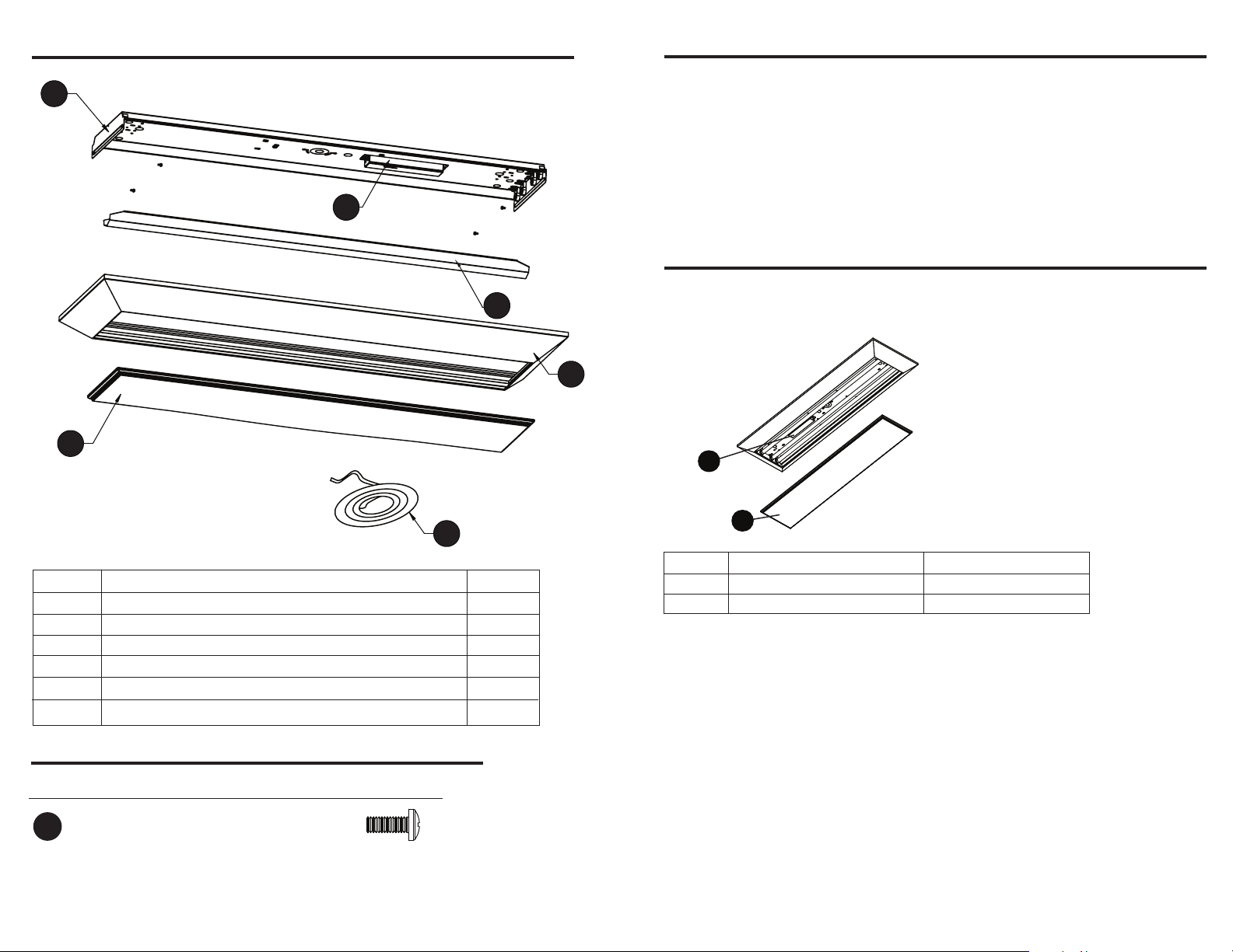
PACKAGE CONTENTS
A
C
WARRANTY
Fixtures listed herein are warranted to be free from defective materials and workmanship,
and that under appropriate application, installation and operating conditions and when
operated at rated voltage, they will be free from failure of ballasts, lamp holders, or any
component part for a period of two (2) years from date of purchase. Damage incurred in
transit from handling is excluded from the terms of this warranty. This warranty extendsonly
to replacement or repair of defective fixture or components with no labor allowance unless
specifically authorized in writing from factory. This warranty gives you specific rights and you
may have other rights that vary from state to state. For warranty claims call our customer
F
E
B
service department.
REPLACEMENT PARTS LIST
For replacement parts, call our customer service department at
1-800-873-2326, 8 a.m. - 4:30 p.m., EST, Monday - Friday
F
D
Part Description Quantity
A
B
C
D
E
F
HARDWARE CONTENTS
Part
AA
Fixture body
Frame
Diffuser
Gasket
Ballast cover (preassembled to Fixture body (A))
Ballast (preassembled to Fixture body (A))
Description
Screw
Quantity
4
1
1
1
1
1
1
2 7
C
Part Description Part #
C
F
Diffuser
Ballast
RP-4000933
2003077
8060362 R.0
Printed in USA
Page 3

ASSEMBLY INSTRUCTIONS
ASSEMBLY INSTRUCTIONS
3. Separate the ballast cover (E) from the fixture
body (A) by squeezing it in at dimples and pulling
it from the assembly. (See Figure 3).
4. Locate the ceiling joists with the stud finder.
Hold fixture body (A) in place and mark the holes.
Drill 1/4 in holes through celiling boards for toggle
bolts (not included) if needed. Be sure that the
supply wires can pass directly into the fixture
body (A). (See Figure 4).
NOTE: When mounted, the mounting hardware
must secure the fixture solidly to the ceiling.
Screws (not included) must penetrate joists
or toggle bolts (not included) must be placed
through the ceiling boards.
5. Remove the appropriate knockout nearest the
power supply wires. Protect wires passing through
hole with snap in brushing (not included).
(See Figure 5).
Figure 3
E
Figure 4
Figure 5
8. Place ballast cover (E) onto fixture body (A).
Figure 8
Squeeze cover and attach under dimples.
A
DO NOT PINCH WIRES. (See Figure 8).
9. Install (4) 32-watt T8 bulbs (not included) into
fixture. Each bulb has 2 pins on each end. Align
the pins with slots and slide bulbs into place.
A
E
Figure 9
ROTATE 90
When all 4 pins are in place, rotate 90°.
(See Figure 9).
10. Install diffuser (C) by sliding one corner
Figure 10
of the lens into a corner of the frame (B) until
the short end of the diffuser is totally inside of
the frame. Slide the diffuser into the frame
B
until the other end of the lens clears the inside
edge of the frame. Lower the diffuser so that it
rests into the bottom of the Frame and adjust
if needed. (See Figure 10).
C
Power to the fixture can now be restored.
6. Mount the fixture with appropriate mounting
hardware (not included) while passing the power
supply wire, the supply neutral wire and the supply
groundwire from junction box or power supply
through the appropriate knockout hole into the
fixture body (A). (See Figure 6).
7. Use wire nut (not included) to connect white
wire from ballast (F) to neutral supply wire. Strip
supply wires if needed. Use wire nut
(not included) to connect black wire from ballast
(F) to power supply wire. Cover wire nuts and
connections completely in electrical tape. Secure
bare or green ground wire to green screw in the
channel of fixture body (A). (See Figure 7).
4 5
Figure 6
A
Figure 7
F
Page 4

CARE AND MAINTENANCE
SAFETY INFORMATION
• Periodically, dust the diffuser (inside and out) with a clean dry cloth. Wipe clean with a
slightly damp cloth as needed. Never use abrasive cleansers.
• Bulb Replacement: Use (4) 32-watt linear bulbs.
TROUBLESHOOTING
Problem Possible Cause Corrective Action
Light fails to illuminate
Light flickers blinks or
lights ends only
1. Fixture wiring problem 1. Check wiring for loose connections
2. No power or failed switch 2. Check power and switch
3. Worn-out lamp(s) 3. Replace lamp(s) as needed
4. Failed ballast 4. Replace ballast as needed
1. Fixture not properly grounded 1. Check grounding system
2. Wrong lamp(s) 2. Verify lamp is listed on ballast
3. One or more failing lamps 3. Replace lamps as needed
4. Failing ballast 4. Replace ballast as needed
WARNING
• For installation in dry or damp residential applications.
• Read all safety precautions and installation instructions carefully before installing
or servicing this fixture. Failure to comply with these instructions could result in
potentially fatal electricshock and/or property damage.
• It is recommended that a qualified electrician perform all wiring. This fixture must
be wired in accordance with all national and local electrical codes. To reduce the
risk of electrical shock, and to assure proper operation, this fixture must be
adequately grounded.
CAUTION
• Instant-on 120 volt, 60Hz electronic ballast with minimum 0°F start.
• Do not handle any energized fixture or attempt to energize any fixture with wet
hands or while standing on a wet or damp surface or in water.
• Disconnect electrical power before installing or servicing any part of this fixture.
If lamp is marked Hg it contains Mercury. Follow disposal laws. See www.epa.gov/bulbrecycling
PREPARATION
Before beginning assembly of product, make sure all parts are present. Compare parts with
package contents list and diagram above. If any part is missing or damaged, do not attempt
to assemble the product. Contact customer service for replacement parts.
Estimated Assembly Time: 45 minutes
Tools Required for Assembly (not included): (2) Mounting screws or toggle bolts,
(2) wire nuts, electrical tape, eye protection, Phillips screwdriver, ladder, wire cutter,
pliers, wire stripper, stud finder, drill with 1/4 in. bit.
ASSEMBLY INSTRUCTIONS
1. Disconnect electrical power before installing
fixture. To prevent light leaks between fixture
and ceiling, attach supplied gasked (D) to frame
(B), adhesive side facing frame. Follow the special
instructions found in the bag containing the gasket
material. (See Figure 1).
2. Locate holes on end plates of fixture body (A)
and remove the 3/8” knockouts. Place fixture
body (A) into frame (B) and locate the pre-drilled
holes on the inside of the frame. Use screws (AA)
to attach the fixture body (A) to the frame (B).
(See Figure 2). NOTE: Do not over-tighten
the screws.
Hardware Used
AA
Screw
x 4
6 3
Figure 1
D
B
Figure 2
B
A
AA
 Loading...