

Page 1
LLEEDDSS EEFFFFEECCTT
EEFFFFEETT AA LLEEDDSS
COMBO-LED
( 15-1872 )
GB - INSTRUCTION MANUAL
F - MANUEL D’UTILISATION
© Copyright LOTRONIC 2014 COMBO-LED Page 1
Page 2

Thank you for having chosen our AFX LIGHT LED EFFECT. For your own safety, please read this user manual
carefully before installing the device.
SAFETY INTRODUCTION
If the device has been exposed to temperature changes due to environmental changes, do not switch it on
immediately. The arising condensation could damage the device. Leave the device switched off until it has
reached room temperature.
It is essential that the device is earthed. A qualified person must carry out the electric connection.
Make sure that the available voltage is not higher than stated at the end of this manual.
Make sure the power cord is never crimped or damaged. If it is damaged, ask your dealer or authorized agent to
replace the power cord.
Always disconnect from the mains, when the device is not in use or before cleaning it. Only handle the power cord
by plug. Never pull out the plug by tugging the power cord.
DISCONNECT DEVICE: Where the MAINS plug or an appliance coupler is used as the disconnect device, the
disconnect device shall remain readily operable.
Shields, lenses or ultraviolet screens shall be changed if they have become visibly damaged to such an extent
that their effectiveness is impaired, for example by cracks or deep scratches.
The lamp shall be changed if it has become damaged or thermally deformed
CAUTION:
1. Be very careful during installation. Since you will be working with a dangerous voltage you can suffer a
life-threatening electric shock when touching live wired.
2. Never look directly into the light source, as sensitive persons may suffer an epileptic shock.
3. Please be aware that damages caused by manual modifications to the device are not subject to warranty. Keep
away from children and non-professionals.
4. The light doesn’t include any spare parts for repair, please check if all the parts are well installed and screws are
fitted tightly before operating. Do not use the light when the cover is open.
GENERAL GUIDELINES
This device is only allowed to be operated with an alternating current of max. 100-240VAC/50-60Hz and was
designed for indoor use only.
Do not shake the device. Avoid brute force when installing or operating it.
When choosing the installation spot, please make sure that the device is not exposed to extreme heat, moisture
or dust. The minimum distance between light-output from the projector and the illuminated surface must be more
than 1 meter. Keep a distance to any flammable objects of at least 5m.
Operate the device only after having familiarized yourself with its functions. Do not permit operation by person not
qualified for operating the device. Most damages are the result of unprofessional operation.
Please use the original packaging if the device is to be transported.
For safety reasons, please be aware that all modifications on the device are forbidden. Furthermore, any other
operation may lead to short-circuit, burns, electric shock, lamp explosion, crash, etc. If this device will be
operated in any way different to the one described in this manual, the product may suffer damages and the
guarantee becomes void.
© Copyright LOTRONIC 2014 COMBO-LED Page 2
GB
Page 3
MOUNTING
Orientation
This fixture may be mounted in any position, provided there is adequate room for ventilation
It is important never to obstruct the fan or vents pathway.
When selecting installation location, take into consideration lamp replacement access and routine maintenance.
Safety cables must always be used.
Never mount in places where the fixture will be exposed to rain, high humidity, extreme temperature changes or
restricted ventilation.
If the external flexible cable or cord of this luminaire is damaged, it shall be exclusively replaced by the manufacturer
or his service agent or a similar qualified person in order to avoid a hazard.
Make sure the installation position is stable before you fix the light. When the light is reverse hanging, make sure the
light will not fall from the truss, use the safety cable go through the truss and bracket of the light as a supporting, to
avoid the light to fall down. There is no entrance to the work area during mounting. Periodically check if the safety
cable has fretted away or clamp is loosened. We will not take any responsibility for damages caused by a badly
installed unit.
Power Supply and Signal Cable Connection
1. Mains Power connection
The exclusive plug should be used between the connection of unit and power. Please ensure that the rated voltage
and frequency are accordance with the power supply. The required input voltage and frequency are: 100-240Vac –
50-60Hz
We suggest that every light has an independent switch so that you can turn on or turn off the light randomly.
Note: the ground wire (yellow/green double-color wire) must be safely connected, the electrical installation must be
in accordance with the related standards
CAUTION: When installing the device, make sure there is no highly inflammable material within a distance of
min.5m!
2. Connection of Signal Cable
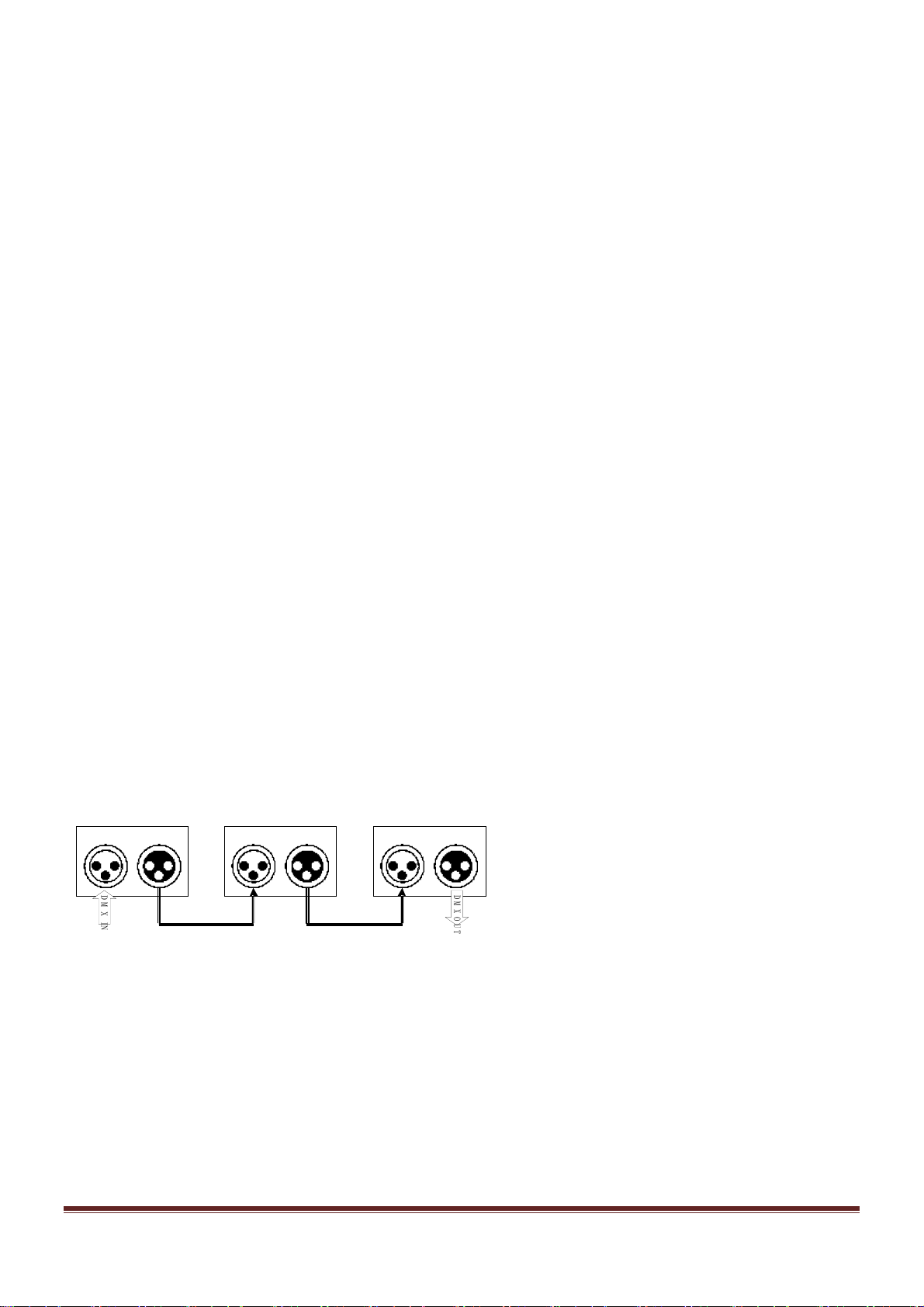
You can use the 3-pin XLR cable to connect the output socket of the master and the input socket of the slave light.
Connect the DIGITAL OUT socket of the master and the IN socket of the slave light, then, connect the OUT socket to
the IN socket of the next light. Ordinal to connect all the lights as below:
12 3
IN
OUT OUT
IN
OUT
IN
D
M
X
I
N
D
M
X
O
U
T
The connection between the output of master and input of product, it’s available to use the 3 pins XLR cable which
provided by the manufacturer. Signal cable from the DMX output of the controller to the input of the first master light,
and connect to the DMX input of second slave light from the DMX output of the first master light, analogously, till
connected all the slave lights, and insert the last connector to the output of the final light. (Notice: the diameter of
core of every cable should be 0.5mm at least, double core shelter cable should be used).The signal connecting must
use the attached 3 pins XLR cable. Notice, all the internal lead wire of the 3 pins XLR cable should not touch to each
other or connect to the connector.
A DMX signal terminator is recommended on the last unit of the chain. DMX terminator is a XLR connector with a
120Ω resistor between the pin 2 and pin 3 of the XLR connector
© Copyright LOTRONIC 2014 COMBO-LED Page 3
Page 4

DMX512 [Address Settings]
This feature allows you to change the device address value.
Press the "MENU" key one or more times until d001 will be display, and then use "UP" or "DOMN" button to choose
the value of "001 ---- 512".
Press ENTER to validate the address.
d001-d512 : 8 channel mode
MASTER SLA VE OPERATING
Set the first COMBO-LED of the link in auto or sound mode. This one is the master device.
Set the others COMBO-LED of the link in DMX mode ( d001 ). These ones are slave devices.
The slave devices will do the same effect as master device.
MODE setting
DMX : Press the MENU button until d001 will be display then use UP and DOWN buttons to set the DMX
address.
SOUND : Press the MENU button until S1XX to S7XX will be display. COMBO-LED will be operate with sound.
( XX are speed value ( 01 to 09 ))
8 sound modes : S1-- = sound program 1
S2-- = Sound program 2 ( no flash )
S3-- = Sound program 3 ( flash )
S4-- = Sound program 4 ( effect led )
S5-- = Sound program 5 ( laser )
S6-- = Sound program 6 ( strobe led )
S7-- = Sound program 7 ( Effect led + laser )
For each sound mode, you can adjust speed from 1 to 9 ( using Up and Down buttons )
AUTO : Press the MENU button until
A1XX to A8XX will be display. COMBO-LED will be operate in automatic mode.
( XX are speed value ( 01 to 09 ))
8 auto modes : A1-- = Auto program 1
A2-- = Auto program 2 ( no flash )
A3-- = Auto program 3 ( flash )
A4-- = Auto program 4 ( effect led )
A5-- = Auto program 5 ( laser )
A6-- = Auto program 6 ( strobe led )
A7-- = Auto program 7 ( Effect led + laser )
© Copyright LOTRONIC 2014 COMBO-LED Page 4
Page 5
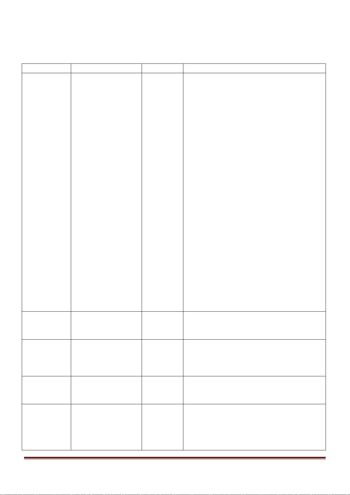
1. Working channel table
8 DMX channels mode
DMX CHANNEL FUNCTION DMX VALUE DESCRIPTION
1
COULEUR
2 EFFECT MOTOR 000-010
3
4
5
( X# is led number )
LASER
LASER MOTOR
STROBE LED
000-010
011-020
021-030
031-040
041-050
051-060
061-070
071-080
081-090
091-100
101-110
111-120
121-130
131-140
141-150
151-160
161-170
171-180
181-190
191-200
201-210
211-220
221-230
231-240
241-250
251-255
011-127
128-255
000-010
011-100
101-200
201-255
000-010
011-200
201-255
000-010
011-020
021-030
031-040
041-050
OFF
RED
GREEN
BLUE
WHITE
AMBER
RED + GREEN
RED + BLUE
RED + WHITE
RED + AMBER
GREEN + BLUE
GREEN + WHITE
GREEN + AMBER
BLUE + WHITE
BLUE + AMBER
RED + BLUE + AMBER
RED + GREEN + AMBER
BLUE + WHITE + AMBER
GREEN + WHITE + AMBER
RED + WHITE + AMBER
GREEN + BLUE + WHITE + AMBER
RED + BLUE + WHITE + AMBER
RED + GREEN + WHITE + AMBER
RED + GREEN + BLUE + AMBER
RED + GREEN + BLUE + WHITE
RED + GREEN + BLUE + WHITE + AMBER
NO FUNCTION
CLOCKWISE ROTATION ( FROM SLOW TO FAST )
UNCLOCKWISE ROTATION ( FROM SLOW TO FAST )
LASER OFF
LASER RED ON – LASER GREEN OFF
LASER GREEN ON – LASER RED OFF
LASER RED AND GREEN ON
NO FUNCTION
CLOCKWISE ROTATION ( FROM SLOW TO FAST )
UNCLOCKWISE ROTATION ( FROM SLOW TO FAST )
ALL OFF
1#
2#
3#
4#
© Copyright LOTRONIC 2014 COMBO-LED Page 5
Page 6

051-060
061-070
071-080
081-090
091-100
101-110
111-120
121-130
131-140
141-150
151-160
161-170
171-180
181-190
191-200
201-210
211-220
221-230
231-240
241-250
251-255
6 STROBE 000-010
011-255
7 MODE 000-010
011-200
201-255
8 SPEED MODE 000-255 AUTO / SOUND SPEED CONTROL ( FROM SLOW TO FAST )
1# + 2# + 3# +4# + 5# + 6# + 7# + 8#
STROBE ( FROM SLOW TO FAST )
5#
6#
7#
8#
1# + 5#
2# + 6#
3# + 7#
4# + 8#
1# + 2#
3# + 4#
5# + 6#
7# + 8#
1# + 8#
4# + 5#
1# + 3# + 5#+ 7#
2# + 4# + 6# + 8#
3# + 4# + 5# + 6#
1# +2# + 7# + 8#
1# +2# + 3# +4#
5# + 6# + 7# + 8#
NO STROBE
DMX MODE
AUTO MODE
SOUND MODE
The following points have to be considered during the inspection:
All screws for installing the devices or parts of the device have to be tightly connected and must not be corroded.
There must not be any deformations on the housing, glass pane, fixations and installation spots.
The electric power supply cables must not show any damage, material fatigue or sediments. Further instructions
depending on the installation spot and usage have to be adhered to by a skilled installer and any safety problems
have to be removed.
We recommend a frequent cleaning of the device. Please use a moist, lint-free cloth. Never use alcohol or solvents.
CAUTION: Disconnect from mains before starting maintenance operation!
Cleaning and Using Frequency of Product
Please make sure that the light is power off before dismantling or maintaining, it’s very important to keep the light
clean. Frequent cleaning will ensure maximum brightness output, but also prolong the life time. It’s suggested to use
the high quality, professional glass detergent and soft cloth to clean the light. It’s not allowed to use alcohol or
chemical solvent. The inner part of the light should be cleaned by vacuum cleaner at least once a year.
When the light doesn’t work, please check if the fuse is burnt out or not. If it is, the same fuse should be replaced,
find out the faulty and restart the light. But please note the repair must be handled by professional.
© Copyright LOTRONIC 2014 COMBO-LED Page 6
Page 7

TECHNICAL SPECIFICATIONS
Channels: .................................................................................................. 8 DMX Channels
Control mode: .................................................. Sound activated, Auto, Master/ Slave, DMX
LED power: ............................................5 x 3W RGBAW LEDs (1R + 1G + 1B + 1W + 1A )
............................................................................. 8 x 1W white led ( for strobe )
Laser: ....................................................................................... Red 100mW + Green 50mW
Working environment: .......................................................................... indoor, 20°C – 40°C
Voltage: .................................................................................................. AC 100-240V ±10%
Frequency: ............................................................................................................... 50-60Hz
Power: ............................................................................................................................ 60W
Dimensions: ........................................................................................... 320 x 320 x 280mm
N.W .............................................................................................................................. 4.5Kg
Electric products must not be put into household waste. Please bring them to a recycling centre.
Ask your local authorities or your dealer about the way to proceed.
© Copyright LOTRONIC 2014 COMBO-LED Page 7
Page 8

Nous vous remercions pour l’achat de Cet EFFETS A LED AFX LIGHT. Pour votre sécurité, lisez attentivement ce
manuel avant d’installer l’appareil.
CONSIGNES DE SECURITE ET D’UTILISATION
Si l’appareil a été exposé à des changements de température, ne le mettez pas immédiatement sous tension. La
condensation qui peut se produire, risque d’endommager les circuits. Attendez que l’appareil ait atteint la
température ambiante avant de le mettre sous tension.
Ne pas bouger l’appareil lorsqu’il est en fonctionnement, la lampe peut se détériorer. La garantie ne prendra pas
en charge ce type de panne qui relève d’une mauvaise utilisation.
L’appareil fait partie de la classe de protection I. Il est donc primordial qu’il soit relié à la terre.
Assurez-vous que la tension secteur ne dépasse pas celle indiquée à la fin de ce mode d’emploi.
Ne jamais faire fonctionner le l’appareil sans le verre de protection ou avec un verre cassé. Demandez à votre
revendeur ou à un technicien de remplacer le verre.
Assurez-vous que le cordon d’alimentation n’est pas écrasé ou endommagé. Dans ce cas, demandez à votre
revendeur ou un technicien de remplacer le cordon.
Débranchez toujours l‘appareil du secteur lorsqu’il n’est pas utilisé ou avant de le nettoyer. Ne tirez que sur la
fiche, jamais sur le cordon.
Lorsque le cordon d'alimentation ou un coupleur d'appareil est utilisé comme dispositif de déconnexion, ce
dispositif doit rester facilement accessible;
Si un interrupteur omnipolaire est utilisé comme dispositif de déconnexion, l'emplacement sur l'appareil et la
fonction de l'interrupteur doit être décrite, et le commutateur doit rester facilement accessible
Des protections, lentilles ou écrans ultraviolets doivent être remplacés lorsqu’ils sont visiblement endommagés au
point qu’ils perdent leur efficacité p.ex. par des fissures ou des égratignures profondes.
Il faut impérativement changer la lampe lorsqu’elle est endommagée ou déformée par la chaleur.
ATTENTION :
1. Soyez très prudent lors de l’installation. Puisque vous travaillez avec des tensions dangereuses, vous pouvez
subir un choc électrique grave si vous touchez des fils nus sous tension.
2. Ne jamais regarder directement dans la source de lumière. Elle peut provoquer une crise d’épilepsie chez des
personnes sensibles.
3. Les dommages résultant du non respect des instructions ou de la modification de l’appareil ne sont pas couverts
par la garantie. Tenir loin des enfants et des personnes non-qualifiées.
4. L’appareil ne contient aucune pièce remplaçable. Vérifiez si toutes les pièces sont bien installées et que les vis
sont bien serrées avant la mise en service. Ne pas utiliser l’appareil lorsque le boîtier est ouvert.
© Copyright LOTRONIC 2014 COMBO-LED Page 8
F
Page 9

REGLES GENERALES
Cet appareil doit être alimenté uniquement en courant alternatif de 100-240Vac/50-60Hz et utilisé uniquement à
l’intérieur.
Ne pas secouer l’appareil. Ne pas forcer pendant l’installation ou l’utilisation.
Lors du choix du lieu d’installation, assurez-vous que l’appareil n’est pas exposé à la chaleur, l’humidité ou la
poussière. La distance minimum entre la sortie lumineuse de la lyre et la surface éclairée doit être de plus de 1m.
Respectez une distance de sécurité d’au moins 5m avec des matériaux ou objets inflammables.
Utilisez cet appareil uniquement si vous vous êtes familiarisés avec ses fonctions. Ne pas autoriser une personne
inexpérimentée d’utiliser cet appareil. La plupart des dommages résultent d’une mauvaise utilisation.
Conservez l’emballage d’origine pour tout transport.
Pour des raisons de sécurité, il est interdit de modifier cet appareil de quelque sorte que ce soit. Toute
manipulation non décrite dans ce manuel peut conduire à des courts-circuits, un choc électrique, l’explosion de
la lampe, une chute, etc. et invaliderait la garantie.
MONT AGE
Orientation
Vous pouvez installer cet appareil dans n’importe quelle position pourvu qu’il y ait suffisamment d’espace pour
assurer une ventilation suffisante.
Il est impératif de maintenir les orifices de ventilation dégagés.
Lorsque vous installez l’appareil, choisissez un emplacement qui permet d’accéder facilement à la lampe pour le
remplacement et d’effectuer l’entretien de routine.
Utilisez toujours des câbles de sécurité.
Ne jamais installer l’appareil à un endroit où il sera exposé à la pluie, à l’humidité, aux changements soudains de
température ou à une ventilation insuffisante.
Si le cordon secteur de l’appareil est endommagé, il ne doit être remplacé que par le fabricant ou son agent ou bien
un technicien qualifié afin d’éviter tout risque d’électrocution.
Assurez-vous que l’emplacement prévu est stable avant d’installer le projecteur. Assurez-vous que le projecteur ne
peut pas tomber de la structure en passant un câble d’acier dans la structure et l’étrier. Personne ne doit se trouver
en-dessous de la zone de travail pendant l’installation. Nous déclinons toute responsabilité pour des dommages et
blessures survenus suite à une chute du projecteur en raison d’une mauvaise fixation.
Connexion de l’alimentation et du câble signal
1. Connexion de l’alimentation secteur
Utilisez le cordon fourni pour brancher l’appareil sur le secteur. Assurez-vous que la tension et la fréquence du
secteur correspond à la tension et la fréquence d’alimentation de l’appareil, à savoir : 100-240Vac~50/60Hz.
Chaque appareil doit pouvoir être mis sous et hors tension individuellement.
© Copyright LOTRONIC 2014 COMBO-LED Page 9
Page 10

2. Connexion du câble signal
La connexion entre la sortie du Maître et l’entrée de l‘Esclave se fait au moyen du cordon XLR à 3 broches fourni. La
sortie DMX de la console de commande doit être branchée sur l’entrée DMX du premier Maître. Branchez la sortie
DMX du Maître sur l’entrée DMX de l’Esclave et ainsi de suite jusqu’au dernier Esclave. Branchez une terminaison
sur la sortie du dernier appareil afin d’éviter des parasites. Cette résistance de fin de ligne consiste en une fiche XLR
qui comporte une résistance de 120Ω entre les broches 2 et 3.
12 3
IN
OUT OUT
IN
OUT
IN
D
M
X
I
N
D
M
X
O
U
T
Note: Utilisez du câble à double blindage. Le diamètre du conducteur de chaque câble doit être d’au moins 0,5mm.
REGLAGE DE L’ADRESSE DMX
Cette fonction vous permet de changer l’adresse DMX de l’appareil.
Appuyez une ou plusieurs fois sur la touche “MENU” jusqu’à ce que d001 s’affiche et choisissez la valeur "001 ----
512" au moyen des touches UP et DOWN ( adresse DMX ).
MODE MAITRE ESCLAVE
Réglez le premier COMBO-LED de la chaîne en mode auto ou musical. Cet appareil sera l’appareil maître.
Réglez les autres COMBO-LED de la chaîne en mode DMX ( d001 ). Ces appareils seront les appareils esclave.
Réglage du MODE
DMX : Appuyez sur MENU jusqu’à ce que d001 s’affiche puis utilisez UP et DOWN pour ajuster l’adresse
DMX.
SOUND : Appuyez sur MENU jusqu’à ce que S1XX à S7XX s’affiche. Le COMBOL-LED fonctionnera au
rythme de la musique.( les XX correspondant à la vitesse de 01 à 09 )
7 modes musical : S1-- = programme musical 1
S2-- = programme musical 2 ( pas de strobe )
S3-- = programme musical 3 ( strobe )
S4-- = programme musical 4 ( effet led )
S5-- = programme musical 5 ( laser )
S6-- = programme musical 6 ( led strobe )
S7-- = programme musical 7 ( Effet led + laser )
AUTO : Appuyez sur MENU jusqu’à ce que S1XX à S7XX s’affiche. Le COMBO-LED fonctionnera en mode
automatique.( les XX correspondant à la vitesse de 01 à 09 )
7 modes auto : A1-- = programme autol 1
A2-- = programme auto 2 ( pas de strobe )
A3-- = programme auto ( strobe )
A4-- = programme auto 4 ( effet led )
A5-- = programme autol 5 ( laser )
A6-- = programme auto 6 ( led strobe )
A7-- = programme auto 7 ( Effet led + laser )
© Copyright LOTRONIC 2014 COMBO-LED Page 10
Page 11

Canaux DMX
Mode 8 canaux DMX
CANAL DMX FONCTION VALE U DMX DESCRIPTION
1
REGLAGE COULEUR
2 MOTEUR
EFFET LED
3
LASER
4
MOTEUR LASER
5
STROBE LED
( X# est le numero de la led )
000-010
011-020
021-030
031-040
041-050
051-060
061-070
071-080
081-090
091-100
101-110
111-120
121-130
131-140
141-150
151-160
161-170
171-180
181-190
191-200
201-210
211-220
221-230
231-240
241-250
251-255
000-010
011-127
128-255
000-010
011-100
101-200
201-255
000-010
011-200
201-255
000-010
011-020
021-030
031-040
041-050
051-060
ETEINT
ROUGE
VERT
BLEU
BLANC
AMBRE
ROUGE + VERT
ROUGE + BLEU
ROUGE + BLANC
ROUGE + AMBRE
VERT + BLEU
VERT + BLANC
VERT + AMBRE
BLEU + BLANC
BLEU + AMBRE
ROUGE + BLEU + AMBRE
ROUGE + VERT + AMBRE
BLEU + BLANC + AMBRE
VERT + BLANC + AMBRE
ROUGE + BLANC + AMBRE
VERT + BLEU + BLANC + AMBRE
ROUGE + BLEU + BLANC + AMBRE
ROUGE + VERT + BLANC + AMBRE
ROUGE + VERT + BLEU + AMBRE
ROUGE + VERT + BLEU + BLANC
ROUGE + VERT + BLEU + BLANC + AMBRE
PAS DE F ONCTI ON
ROTATION HORAIRE ( DE LENT A RAP IDE )
ROTATION ANTI-HORAIRE ( DE LENT A R APIDE )
LASER ETEINT
LASER ROUGE ALLUME – LASER VERT ETEINT
LASER VERT ALLUME – LASER ROUGE ETEINT
LASER ROUGE ET VERT ALLUMES
PAS DE F ONCTI ON
ROTATION HORAIRE ( DE LENT A RAP IDE )
ROTATION ANTI-HORAIRE ( DE LENT A R APIDE )
TOUTES ETEINTES
1#
2#
3#
4#
5#
© Copyright LOTRONIC 2014 COMBO-LED Page 11
Page 12

061-070
071-080
081-090
091-100
101-110
111-120
121-130
131-140
141-150
151-160
161-170
171-180
181-190
191-200
201-210
211-220
221-230
231-240
241-250
251-255
6 STROBE 000-010
011-255
7 MODE 000-010
011-200
201-255
8 VITESSE MODE 000-255 REGLAGE VITESSE MODE ( DE LENT A RAPIDE )
1# + 2# + 3# +4# + 5# + 6# + 7# + 8#
STROBE ( DE LENT A RAPIDE )
6#
7#
8#
1# + 5#
2# + 6#
3# + 7#
4# + 8#
1# + 2#
3# + 4#
5# + 6#
7# + 8#
1# + 8#
4# + 5#
1# + 3# + 5#+ 7#
2# + 4# + 6# + 8#
3# + 4# + 5# + 6#
1# +2# + 7# + 8#
1# +2# + 3# +4#
5# + 6# + 7# + 8#
PAS STROBE
MDOE DMX
MDOE AUTO
MDOE MUSICAL
Branchement du cordon d’alimentation
Utilisez le cordon fourni pour brancher l’appareil sur le secteur. Vérifiez que votre tension secteur correspond bien à
la tension d’alimentation de l’appareil qui est de 220-240Vcc 50/60Hz. L’effet possède un interrupteur d’alimentation
indépendant. Ainsi vous pouvez facilement allumer et éteindre chaque effet individuellement.
Si le cordon d’alimentation est endommagé, il doit être remplacé par un technicien qualifié. Le cordon de
remplacement doit présenter les mêmes caractéristiques techniques que le cordon d’origine.
ATTENTION :
Lorsque vous installez l’appareil, vérifiez qu’il n’y a pas de matériaux hautement inflammables à une distance
inférieure à 5m !
© Copyright LOTRONIC 2014 COMBO-LED Page 12
Page 13

Les points suivants doivent être vérifiés lors d’une inspection :
1) Toutes les vis utilisées pour l’installation et les composants de l’appareil doivent être fermement branchés et
exempts de corrosion.
2) Le boîtier, la vitre de protection, les fixations et le point d’installation ne doivent présenter aucune déformation.
3) Les cordons d’alimentation électrique ne doivent présenter aucun dommage, ni signes d’usure. L’installateur doit
respecter toutes les consignes de sécurité.
Nous recommandons un nettoyage fréquent de l’appareil. Utilisez un chiffon humide, non-pelucheux. Ne jamais
utiliser d’alcool et de solvants.
ATTENTION :
Débrancher l’appareil du secteur avant d’effectuer des travaux de maintenance.
Entretien
Débranchez l’appareil du secteur avant d’effectuer le nettoyage ou la maintenance. Il est important de garder
l’appareil dans un état de propreté afin d’assurer une luminosité maximale et de prolonger sa durée de vie. Utilisez
un produit de nettoyage à vitre de bonne qualité et un chiffon doux pour nettoyer l’appareil. Ne pas utiliser d’alcool
ou de solvants chimiques pour nettoyer l’appareil. Nettoyez l’intérieur de l’appareil une fois par an au moyen d’un
aspirateur.
Si la lampe ne fonctionne pas, vérifiez si le fusible a sauté. Si c’est le cas, remplacez le fusible par un neuf qui
présente exactement les mêmes caractéristiques techniques que le fusible d’origine. Remettez la lampe sous
tension. Notez que toute réparation doit être effectuée par un professionnel.
CARACTERISTIQUES TECHNIQUES
Canaux DMX .................................................................................................. 8 canaux DMX
Mode: ............................................................................. Musical, Auto, Maître-sclave, DMX
Puissance led: ....................................... 5 x 3W RGBAW LEDs ( 1R + 1V + 1B + 1Bl + 1A )
.................................................................... 8 x 1W blanche ( pour le strobe )
Laser: ....................................................................................... Rouge 100mW + Vert 50mW
Environnement: .............................................................................. intérieure, 20°C – 40°C
Alimentation: .......................................................................................... AC 100-240V ±10%
Fréquence: ............................................................................................................... 50-60Hz
Consommation: .............................................................................................................. 60W
Dimensions: ........................................................................................... 320 x 320 x 280mm
Poids ............................................................................................................................ 4.5Kg
NOTE IMPORTANTE : Les produits électriques ne doivent pas être mis au rebut avec les ordures ména gères. Veuillez les
faire recycler là où il existe des centres pour cela. Consultez les autorités locales ou votre revende ur sur la façon de les
recycler.
© Copyright LOTRONIC 2014 COMBO-LED Page 13
Page 14

© Copyright LOTRONIC 2014 COMBO-LED Page 14
 Loading...