

Page 1
FAST CONNECTOR TERMINATION
AND ASSEMBLY INSTRUCTIONS
This document provides termination instructions for AFL’s FAST SC, LC and ST connectors. Read these instructions carefully
before proceeding. Termination instructions are provided for 250 μm, 900 μm, 2 mm and 3 mm ber/cable. Different termination
options after cleaving the ber are provided for each ber type. Please choose the best option for your application.
WARNING: Always wear eye protection when handling optical bers. Dispose of any cut or cleaved ends properly.
Do not touch the cleaver wedge with bare hands.
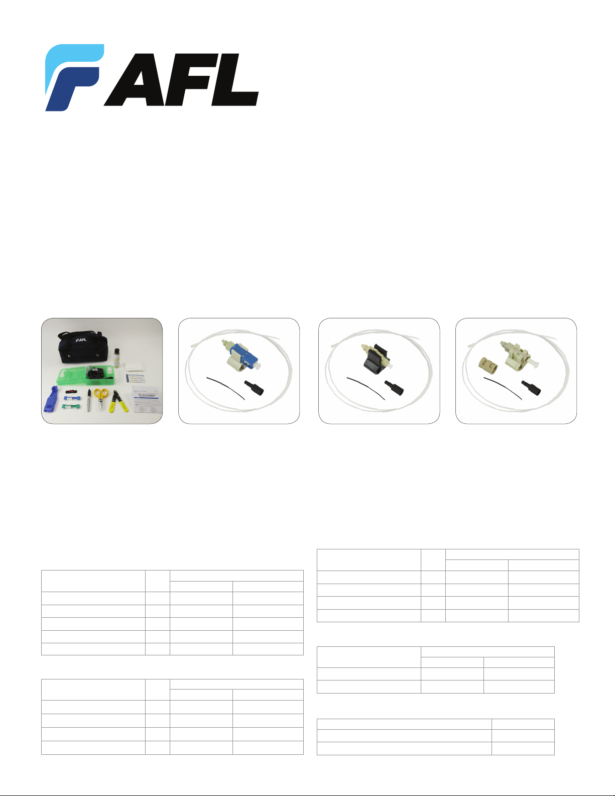
MATERIALS
6 7
1
2
3
4
5
16
8
14 18
15
17
19
20
21
9
11 12 13
10
FAST Connector Universal Tool Kit FAST SC Connector Kit FAST ST Connector KitFAST LC Connector Kit
1. Blue Tool Bag
2. Fiber Preparation Fluid
3. Lint-free Wipes
4. CT-30A Cleaver
5. Strip template
ORDERING INFORMATION
SC CONNECTORS
Fiber Type Color
Multimode 62.5/125 µm, OM1 Beige FAST-SC-MM62.5-6 FAST-SC-MM62.5-100
Multimode 50/125 µm, OM2 Black FAST-SC-MM50-6 FAST-SC-MM50-100
Multimode 50/125 µm 10G, OM3 Aqua FAST-SC-MM50L-6 FAST-SC-MM50L-100
Single-mode, UPC Blue FAST-SC-SM-6 FAST-SC-SM-100
Single-mode, APC-AU Green FAST-SC-SMAU-6 FAST-SC-SMAU-100
LC CONNECTORS
Fiber Type Color
Multimode 62.5/125 µm, OM1 Beige FAST-LC-MM62.5-6 FAST-LC-MM62.5-100
Multimode 50/125 µm, OM2 Black FAST-LC-MM50-6 FAST-LC-MM50-100
Multimode 50/125 µm 10G, OM3 Aqua FAST-LC-MM50L-6 FAST-LC-MM50L-100
Single-mode, UPC Blue FAST-LC-SM-6 FAST-LC-SM-100
6. FAST Assembly Tool
7. 0.25/0.9 mm Cable Clamp
8. 2 mm Cable Clamp
9. 3 mm Cable Clamp
10. Marker
AFL No.
Pack of 6 Pack of 100
AFL No.
Pack of 6 Pack of 100
11. Kevlar® Scissors
12. Fiber Stripper
13. FAST Termination Instructions
14. Clear Protective Tubing
15. FAST SC Connector
ST CONNECTORS
Fiber Type Color
Multimode 62.5/125 µm, OM1 Beige FAST-ST-MM62.5-6 FAST-ST-MM62.5-100
Multimode 50/125 µm, OM2 Black FAST-ST-MM50-6 FAST-ST-MM50-100
Multimode 50/125 µm 10G, OM3 Aqua FAST-ST-MM50L-6 FAST-ST-MM50L-100
Single-mode, UPC Blue FAST-ST-SM-6 FAST-ST-SM-100
BOOT KITS
Item Description
2 mm Boot Kit, SC/LC/ST FAST-BOOT-2MM-6 FAST-BOOT-2MM-100
3 mm Boot Kit, SC/LC/ST FAST-BOOT-3MM-6 FAST-BOOT-3MM-100
TOOL KITS
Item Description AFL No.
FAST Universal Tool Kit with CT-30A Cleaver CS001201
FAST Universal Tool Kit with CT-05A Cleaver CS010975
16. 250 µm Tubing
17. 900 µm Boot
18. Clear Protective Tubing
19. FAST LC Connector
20. 250 µm Tubing
24
25
21. 900 µm Boot
22. Clear Protective Tubing
23. FAST ST Connector
24. ST Connector Housing
25. 250 µm Tubing
26. 900 µm Boot
AFL No.
Pack of 6 Pack of 100
AFL No.
Pack of 6 Pack of 100
22
23
26
(800) 235-3423 • (864) 433-0333 • www.AFLglobal.com
Page 2
250 µm FIBER TERMINATION
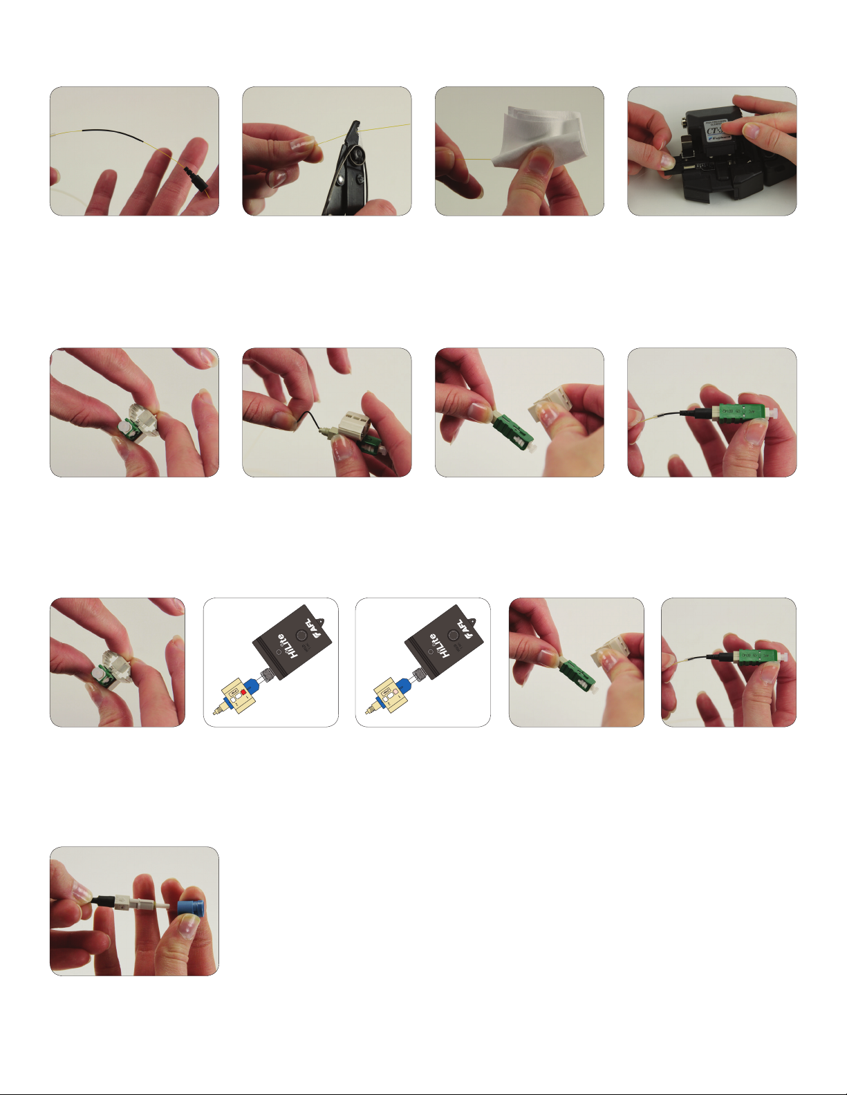
1: Insert the clear protective tubing,
250 μm protective tubing and
900 μm boot onto the ber.
2: Strip 35 mm of 250 μm coating
from the ber.
3: Clean the ber with a lint-free
wipe and ber preparation uid.
TERMINATION OPTION A: MANUAL
1: Squeeze top and bottom of the
wedge to ensure that it is engaged.
2: Insert ber into connector. Bring
250 μm protective tubing forward.
Create a slight bend in the ber to
maintain connection.
3: Release the wedge clip by
squeezing both sides. Remove the
wedge clip.
TERMINATION OPTION B: VISUAL FAULT IDENTIFIER (VFI)
4: Set the ber on the cleaver at the
10.5 mm cleave length. Cleave the ber.
4: Slide the boot onto the connector
body. Bring the clear protective tubing
over the end of the 250 μm protective
tubing. Termination is complete.
1: Squeeze top and bottom of
the wedge to ensure that the
wedge is engaged.
2: Remove the dust cap.
Insert the connector into the
VFI. Window 1 of the wedge
clip will glow red.
FOR ST ONLY
Apply the connector housing to the
connector body. You will not be able
to reengage the wedge clip after the
housing is applied.
3: Insert the ber into the
connector. Bring 250 μm
protective tubing forward.
The light will dim when a
connection is made.
(800) 235-3423 • (864) 433-0333 • www.AFLglobal.com
4: Release the wedge clip by
squeezing both sides. Remove
the wedge clip.
5: Slide the boot onto the
connector body. Bring the
clear protective tubing over
the end of the 250 μm
protective tubing.
Termination is complete.
Page 3
900 µm FIBER TERMINATION
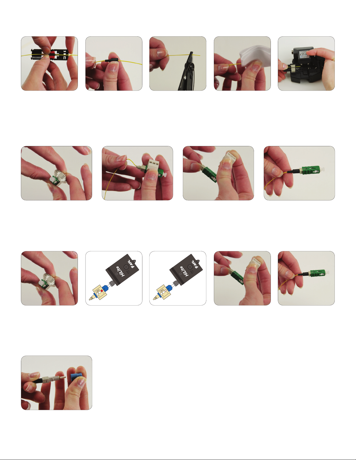
1: If you are using a 900 μm
fanout/breakout kit, place
into 900 μm cable clamp
about 10" from the end
of the cable.
2: Place the 900 μm boot on
the cable.
3: Strip 35 mm of 900 μm
and 250 μm coating off.
4: Clean the ber with a
lint-free wipe and ber
preparation uid.
TERMINATION OPTION A: MANUAL
1: Squeeze top and bottom of the
wedge to ensure that it is engaged.
2: Insert the ber into the connector
with mark facing up. Create a slight
bend in the connector to maintain
connection.
3: Release the wedge clip by
squeezing both sides. Remove
the wedge clip.
TERMINATION OPTION B: VISUAL FAULT IDENTIFIER (VFI)
5: Set the ber on the cleaver
at the 10.5 mm cleave length.
Cleave the ber.
4: Slide the boot onto the connector
body. Termination is complete.
1: Squeeze top and bottom of
the wedge to ensure that the
wedge is engaged.
2: Remove the dust cap.
Insert the connector into the
VFI. Window 1 of the wedge
clip will glow red.
FOR ST ONLY
Apply the connector housing to the
connector body. You will not be able
to reengage the wedge clip after the
housing is applied.
3: Insert the ber into the
connector with the mark
facing up. The light will dim
when a connection is made.
(800) 235-3423 • (864) 433-0333 • www.AFLglobal.com
4: Release the wedge clip by
squeezing both sides. Remove
the wedge clip.
5: Slide the boot onto the
connector body. Termination
is complete.
Page 4
2 MM AND 3 MM FIBER TERMINATION
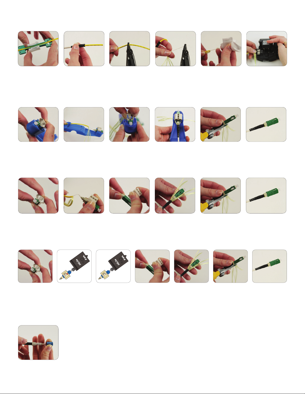
1: Place the cable into
the appropriate cable
clamp about 10" from
2: Insert the appropriate
boot onto the cable.
3: Remove 70 mm of
cable jacket.
4: Strip off 35 mm of
900 μm and 250 μm
coating.
the end of the cable.
TERMINATION OPTION A: FAST ASSEMBLY TOOL
1: Place the connector into
the assembly tool. Squeeze
top and bottom of the wedge
to ensure that it is engaged.
2: Insert the ber into
connector with mark
upward until a slight
bend is made in the ber.
3: Disengage the wedge
by squeezing both sides.
Remove cable from
assembly tool cable grip.
4: Divide the Kevlar® into
two portions and place
them in the Kevlar® grips.
Bring boot forward and
screw on halfway.
TERMINATION OPTION B: MANUAL
5: Clean the ber with
a lint-free wipe and ber
preparation uid.
5: Remove from
assembly tool. Remove
wedge clip completely. Trim
excess Kevlar
Kevlar® scissors.
®
using the
6: Set the ber on the
cleaver at the 10.5 mm
cleave length. Cleave
the ber.
6: Screw the boot on
completely. Termination
is complete.
1: Squeeze top and bottom
of the wedge to ensure
that it is engaged.
2: Insert ber into connector
making sure the mark is
facing up. Create a slight
bend to maintain connection.
3: Release the wedge clip
by squeezing both sides.
Remove the wedge clip.
4: Divide the Kevlar
evenly on both sides.
Screw the boot on halfway.
®
TERMINATION OPTION C: VISUAL FAULT IDENTIFIER (VFI)
1: Squeeze top and
bottom of the wedge
to ensure that the
wedge is engaged.
2: Remove the dust cap.
Insert the connector into
the VFI. Window 1 of the
wedge clip will glow red.
3: Insert the ber into
the connector with the
mark facing up. The
light will dim when a
connection is made.
4: Release the wedge
clip by squeezing both
sides. Remove the
wedge clip.
5: Divide the Kevlar
evenly on both sides.
Screw the boot on
halfway.
FOR ST ONLY
5: Trim excess Kevlar
using the Kevlar® scissors.
®
6: Trim excess Kevlar
using the Kevlar®
scissors.
®
6: Screw the boot on
completely. Termination
is complete.
®
7: Screw the boot on
completely. Termination
is complete.
Place the connector into the assembly
tool. Squeeze top and bottom of the wedge
to ensure that it is engaged. You will not be
able to reengage the wedge clip after the
housing is applied.
(800) 235-3423 • (864) 433-0333 • www.AFLglobal.com
 Loading...