

Page 1
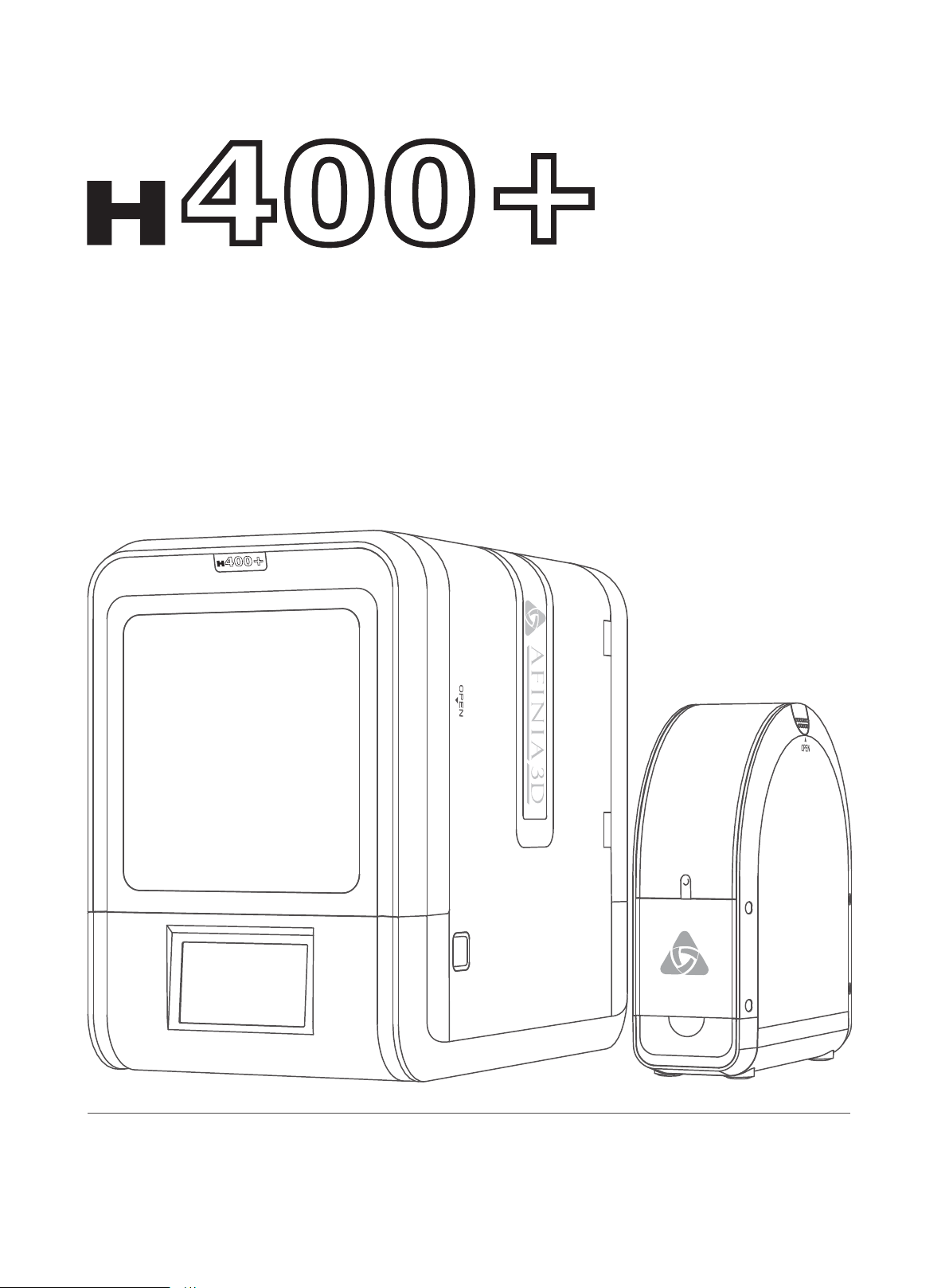
400+
User Manual
V 0.1
400+
Download full user manual at www.afinia.com/support
Page 2

Chapter 1 Product Description
Chapter 2 Prepare for Your First 3D Print
Index
Chapter 3 Product Activation
Chapter 4 Machine Settings
Chapter 5 Print Settings
Chapter 6 Calibration and Other Options
Chapter 7 Techniques and Troubleshooting
Page 3
Safety Precautions
1\ The Afinia H400+ 3D printer requires the power adapter provided by the original manufac -
turer, otherwise the machine could be damaged or even cause are hazard. Please also keep
the power adapter away from water and out of high temperature environments.
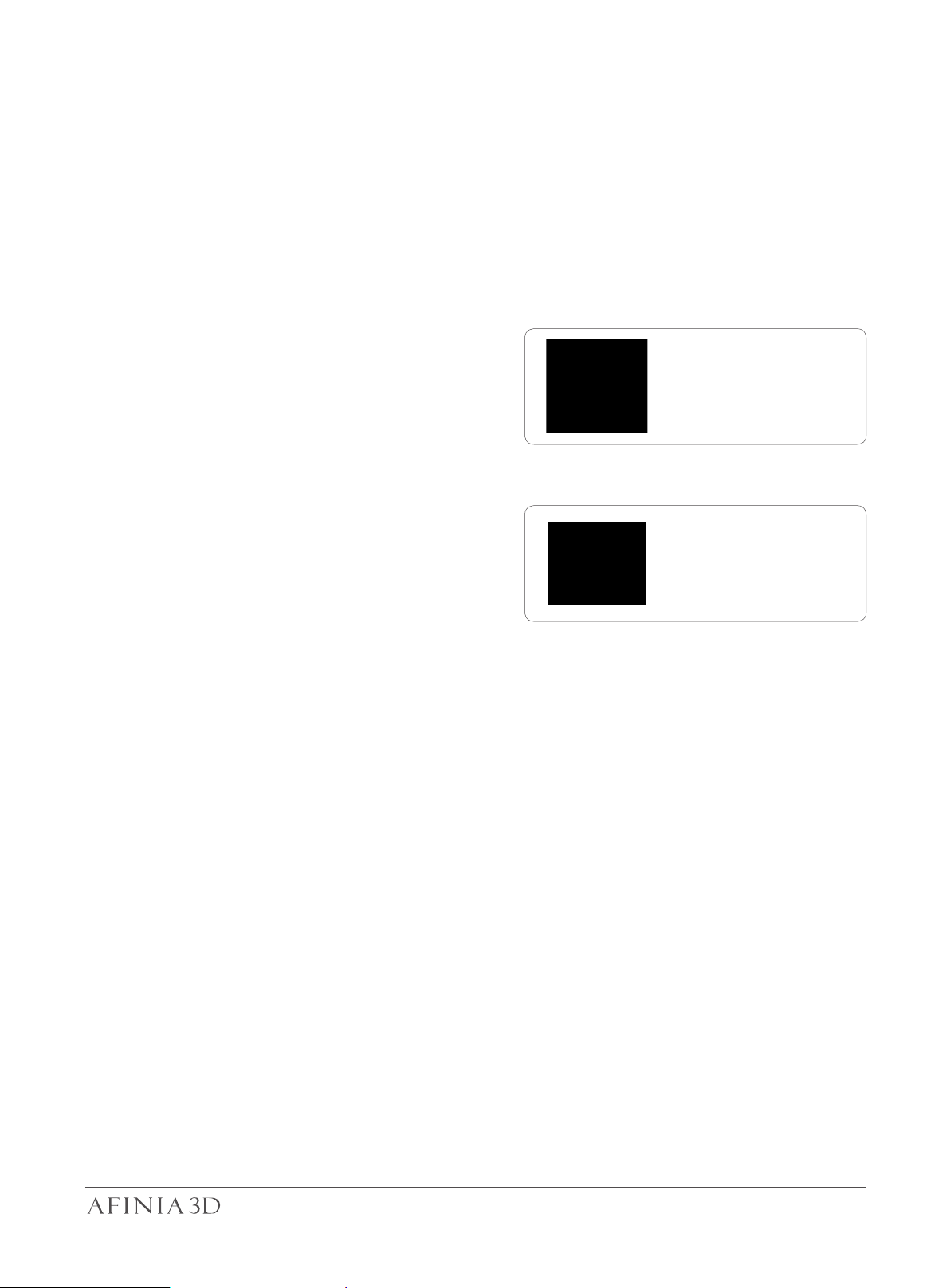
2\ During printing, the nozzle of the printer will
reach 260°C and the print platform could reach
over 70°C. Please do not touch these parts with
your bare hands while they are hot not even
with the heat resistant gloves included with the
machine as the temperature could damage the
gloves and injure your hands.
Warning label:
High Temperature,
do not touch!
3\ During printing, the printhead and other
mechanical parts move at high speeds. Touch-
ing these parts while they are moving could
cause injuries.
4\ Please wear goggles when removing the support material from models and detaching
models from the perf board.
5\ When printing with ABS and PLA, the plastics will create a light odor. Please run the printer
in a well ventilated environment. We also suggest you put the printer in an environment with
a stable temperature as unwanted cooling could cause adverse effects to the print quality.
When the printer is extruding filament, make sure there is enough space between print
nozzle and the platform. Otherwise the nozzle could become blocked.
Warning Label:
Moving parts, do not
touch!
Printing Environment
The Afinia H400's ideal working enironment is temperature between 15°C and 30°C, relative
humidity between 20–50% and altitude below 2000 meters.
Printing at temperatures out of this range could cause adverse effects to the printing process.
When using the “Extrude” function, keep at least 50mm between the nozzle and the platform.
If too close, the nozzle may get blocked.
01
Page 4
Afinia 1-Year Limited Warranty
Below is the one-year limited warranty included with this Afinia product. Afinia prides itself on its outstanding
product line and its technical support. If for some reason, your product fails, Afinia, a division of Microboards
Technology, LLC, stands behind its warranty and assures you the best service possible in a quick and timely
manner.
Afinia warrants to the original purchaser that this product is free from defects in material and workmanship.
Afinia will for one year, at its option, repair or replace at no charge for parts and labor from the date you
purchased the product from an authorized Afinia reseller. Nozzles and Cell/Perf Boards are warranted for
ninety
The abov
merchantibility and fitness for a particular purpose. Afinia, a division of Microboards Technology, LLC, will not
be liable for any other damages or loss, including breach of warranty or negligence.
This product has been thoroughly tested and inspect
your product completely for any damage or loss of parts that may have occurred during shipment. Notify the
delivering carrier promptly if damage claims are to be filed.
Afinia reserves the right to modify or update its product without obligation to replace any equipment delivered
prior to any
(90) days.
- Warranty registration must be completed within 30 days of receipt of the product in order to validate the
warranty.
- Afinia, a division of Microboards Technology, LLC, reserves the right to determine the validity of all warranty
claims.
- Warranty is void if the product serial number has been altered or re
- Warranty is void if the product has been misused or damaged or if evidence is present that the product was
altered, modified, or serviced by unauthorized service people.
e stated warranty is exclusive and replaces all other warranties, express or implied, including those of
ed at the factory prior to shipment. Nevertheless, inspect
such change.
moved.
Compliance
FCC ID:
This device complies with Part 15 of the FCC Rules. Operation is subject to the following two conditions: (1)
this device may not cause harm
including interference that may cause undesired operation.
authority to operate the equipment.
NOTE: This equipment has been tested and found to comply with the limits for a Class B digital device,
pursuant to Part 15 of the FCC Rules. These limits are designed to provide reasonable protection against
harmful interference in a residential installation. This equipment generates, uses, and can radiate radio
frequency energy and, if not installed and used in accordance with the instructions, may cause harmful
interference to radio communications. However, there is no guarantee that interference will not occur in a
particular installation. If this equipment does cause harmfu
can be d
to correct the interference by one or more of the following measures:
- Reorient or relocate the receiving antenna.
- Increase the separation between the equipment and receiver.
- Connect the equipment into an outlet on a circuit different from that to
which the receiver is connected.
- Consult the dealer or an experienced radio/TV technician for help.
etermined by turning the equipment off and on, the user is encouraged to try
FCC CE ROHS
ful interference, and (2) this device must accept any interference received,
party responsible for compliance could void the user’s
l interference to radio or television reception, which
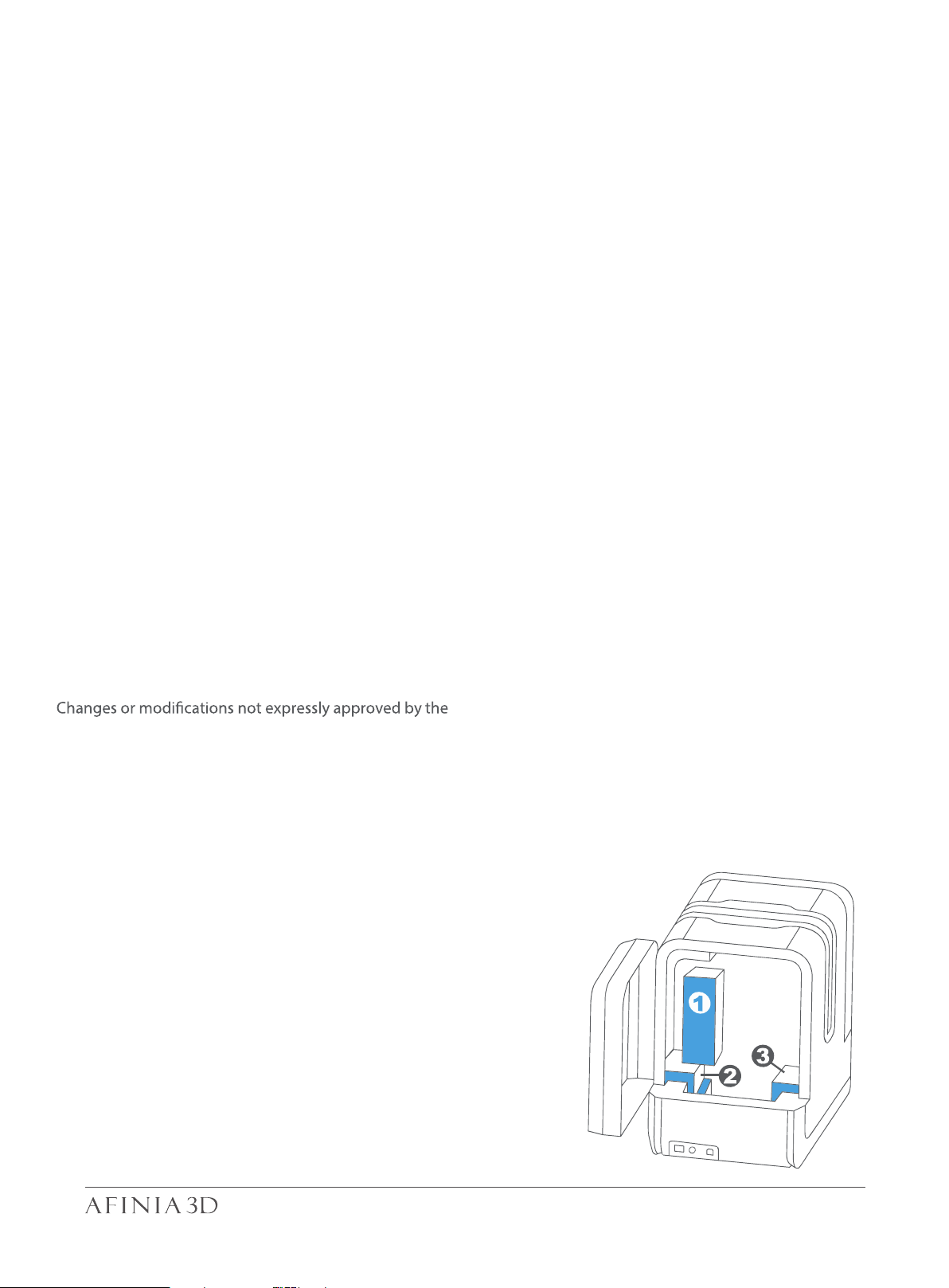
Unpacking
Remove the cushioning foams from the
the printer before use.
inside
Rear View
02
Page 5
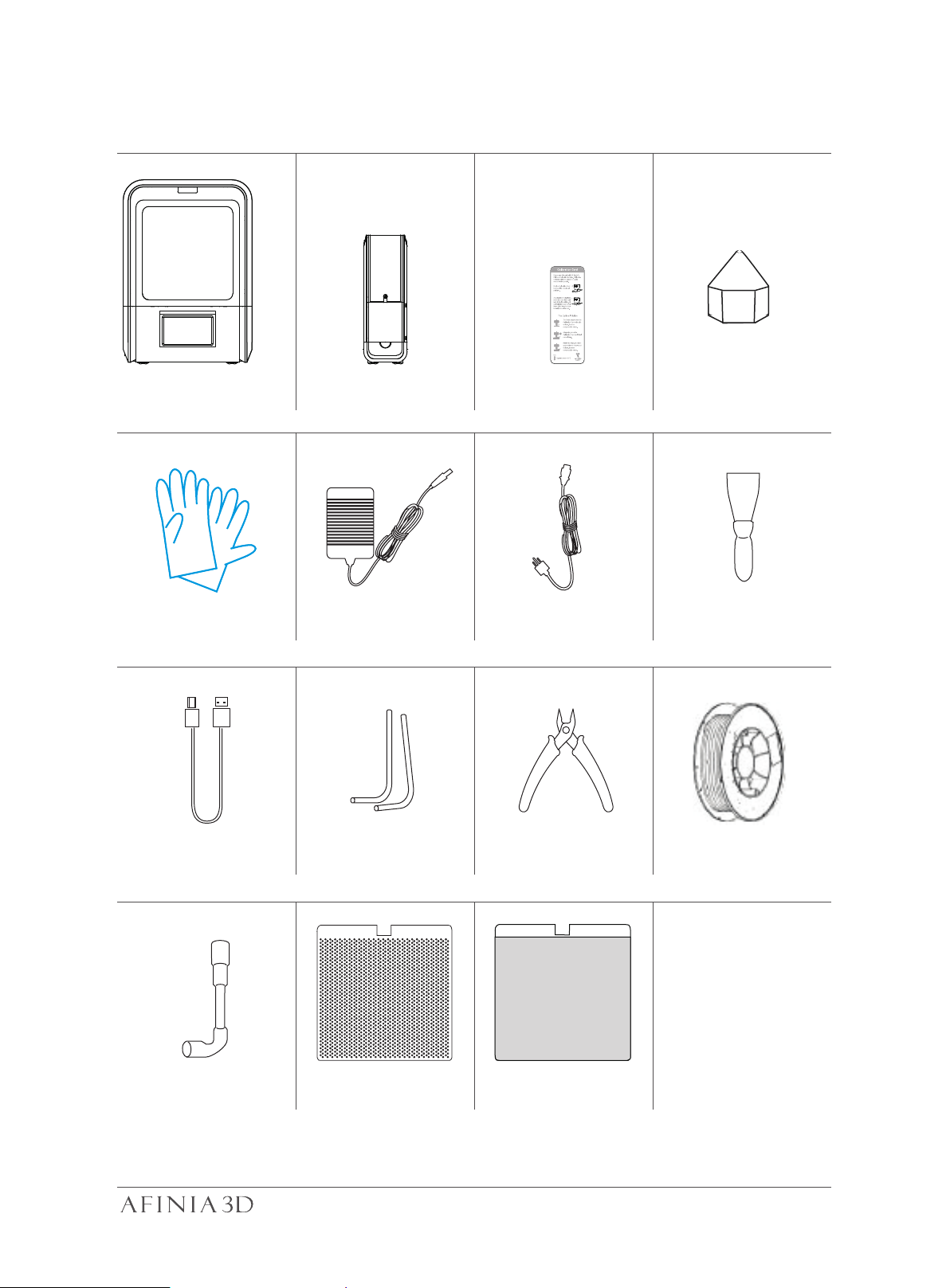
Package Content 1-1
H400+ Spool and Toll Holder Calibration Card
Protective Gloves
USB Cable
Power Adapter
Hex Keys
2.0mm, 2.5mm
Pliers
Nozzle
ScraperPower Cable
ABS Filament
Flex Print
Board
Nozzle Wrench
Perforated Print Board
(Perf Board)
If anything is missing, please contact Afinia 3D support at [email protected]
03
Page 6
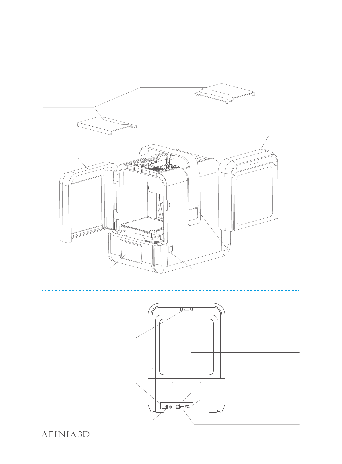
Product Description 1-2
Front Side
Magnetic Top Lids
Back Door
Front Door
LCD Touch Screen
Back Side
Filament Insertion Hole
Power Switch
Handle
Initialization Button
Back Door
USB -B for Computer
USB -A for USB Drive
Power Supply Connector
Ethernet Port
04
Page 7
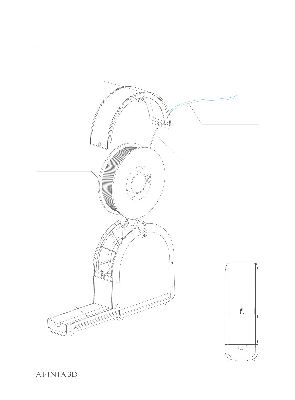
Filament Spool Holder 1-3
Spool Hold Lid
Filament Guiding Tube
Filament
Filament Spool
Tool Drawer
05
Page 8
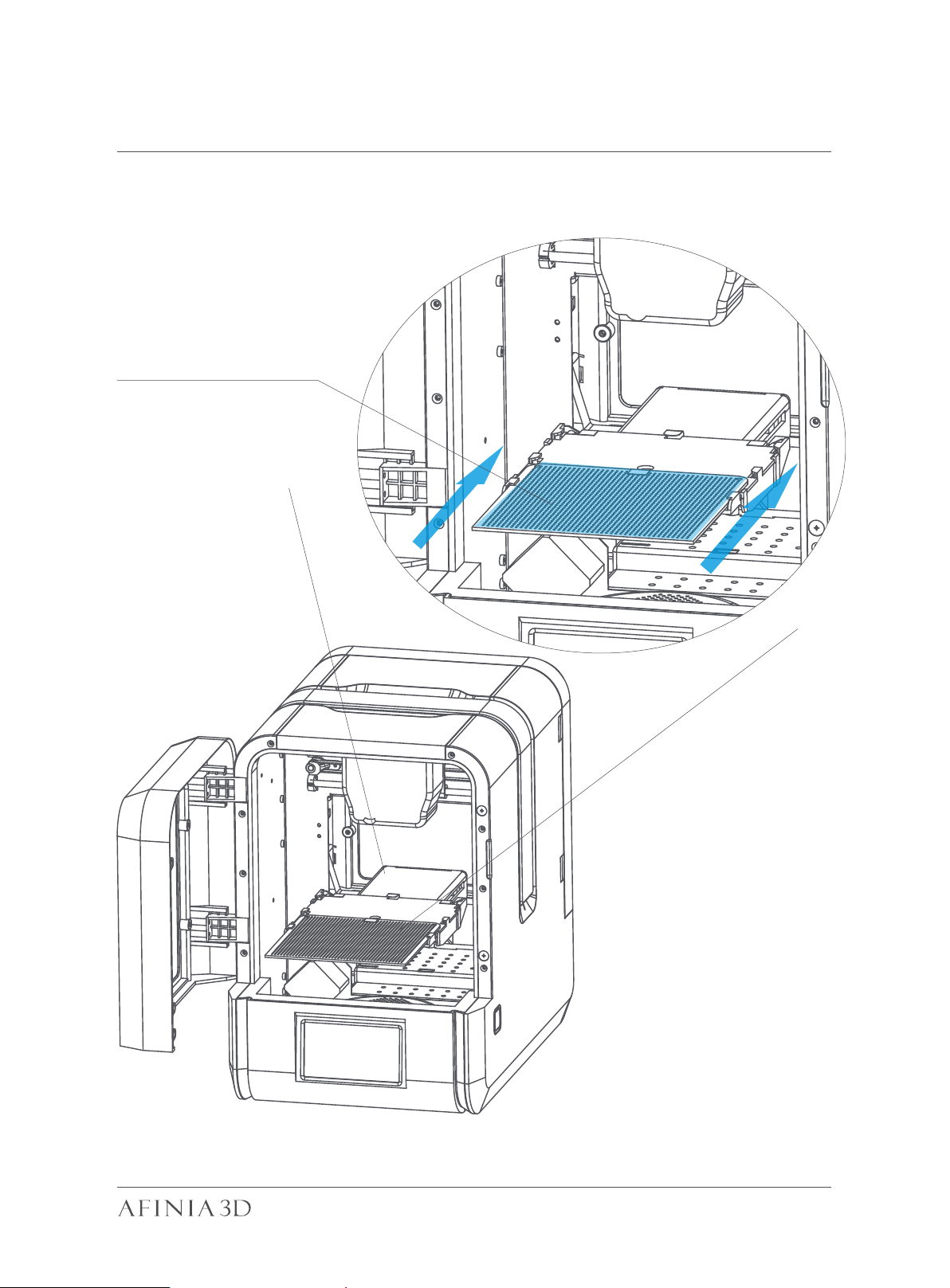
Installation of Print Board 2-1
Slide print board into the
platform
06
Page 9
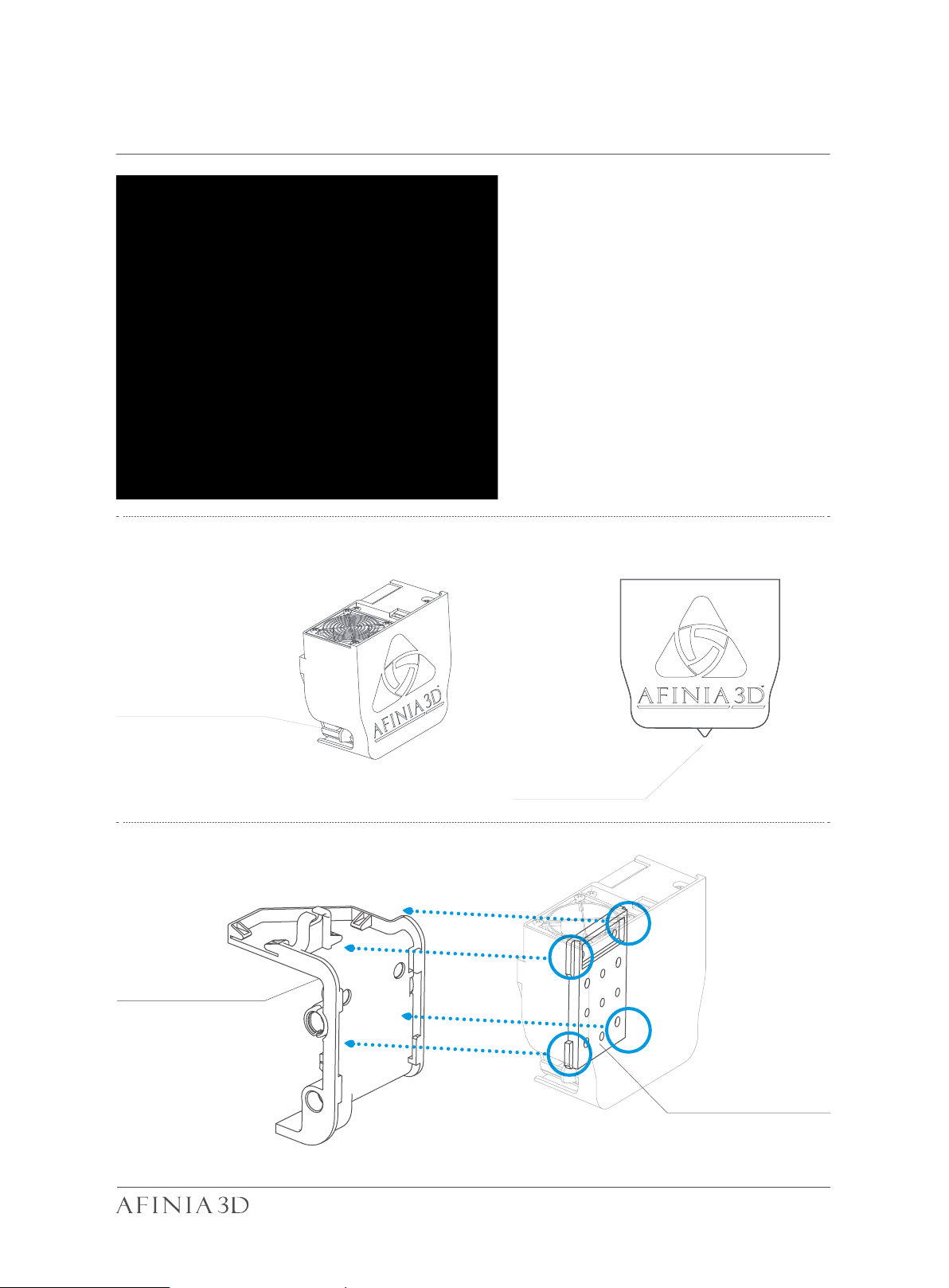
Print Head Installation 2-2
Open front door, back door
and top covers
Cooling Adjustment
knob
Print Head Mount
Nozzle
Print Head Mounting
Plate
07
Page 10
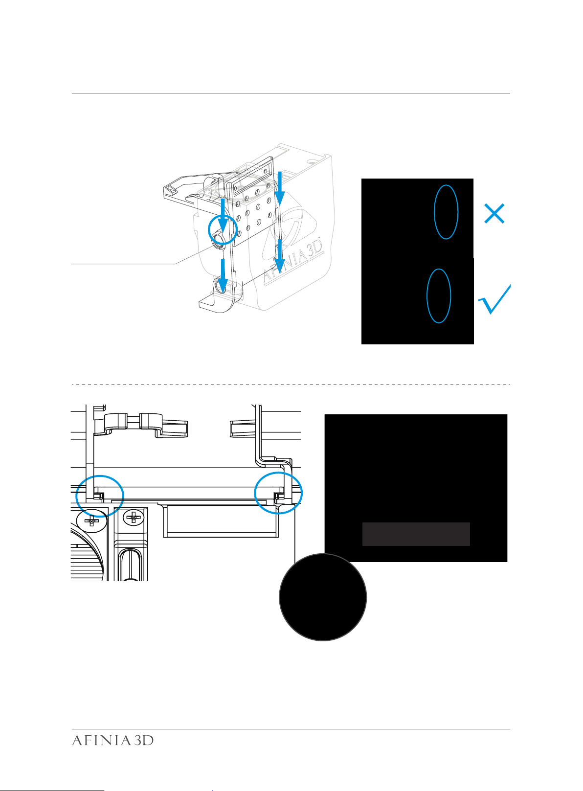
Print Head Installation 2-3
Slide the print head
into the slots.
The Correct Installation of
Printhead FFC cable for the H400+
The print head must be pushed
to the bottom of the mount.
Notice: When installed correctly,
the red and the blue parts should
be at the same level.
08
Page 11

Download and Install Afinia Studio 2-4
Obtain Afinia Studio
Download the Studio software by going to www.afinia.com/support/downloads,
then install it on your computer.
Minimum hardware requirements
Intel Pentium 4 or better CPU 4GB RAM
Display card support OpenGL 2.0
09
Page 12
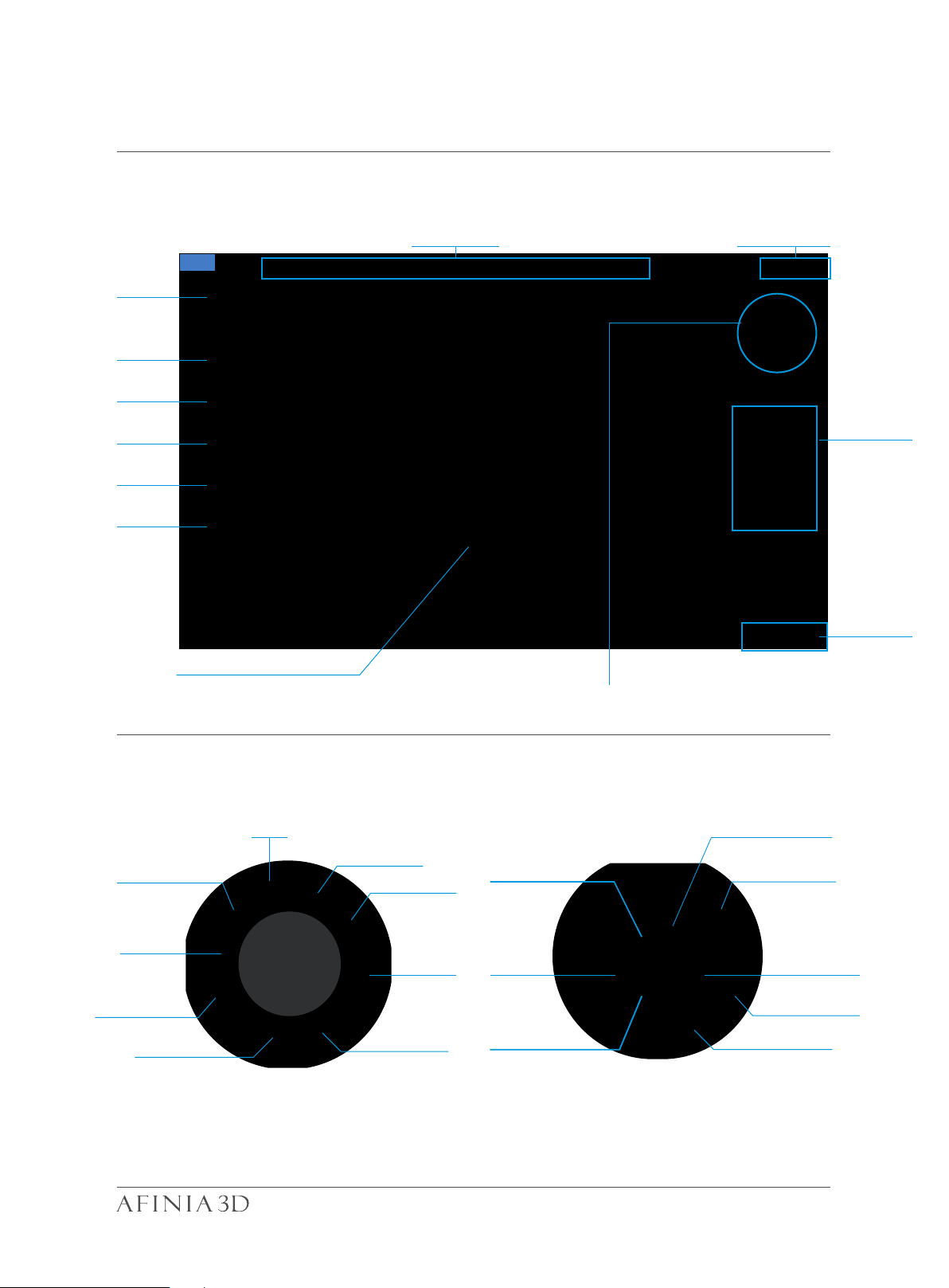
Software Interface 2-5
Home
Load File
Printer Status Other Options
Print
Initialize
Calibrate
Maintenance
Build Platform
Rotate
Move
Scale
More
Model Adjustment Wheel
Fix
Model Info
Print Queue
Save
Back to Menu 1
View
Display Mode
Clip View
Menu 1
Undo
View Angles
Merge
Support Edit Auto place
Reset to Default
Mirror
Menu 2
10
Page 13
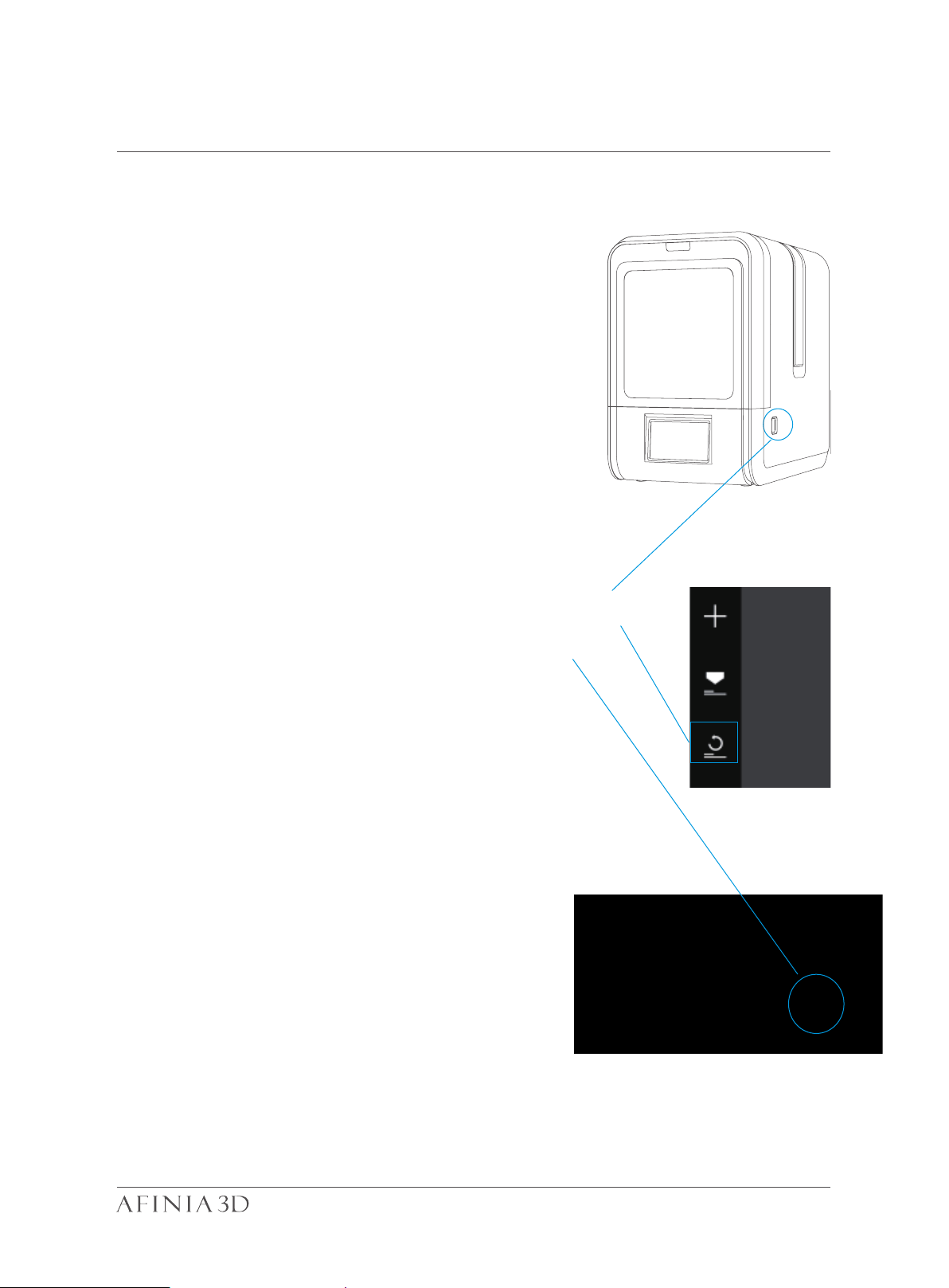
Initialization of Printer 2-6
Initialization is required for every time the
machine is switched on. During initialization,
the print head and print platform move slowly
and hit the endstops of the XYZ axes. This is
essential as the printer needs to find the endpoint of each axis. Many software options will
light up and become available for use only
after initialization.
Initialization
button
There are three ways to initialize
your printer:
Initialization
Button
1. Hold the initialization button on the printer.
2. Clicking the "Initialize" option in the software
menu (shown above).
3. When the printer is idle, press the initialize
button on touch screen.
Other functions of Initialization Button
on the side of the H400+:
1. Stop a print: Press and hold the button.
2. Reprint the last job: Double click the button.
3. Turn on/off internal lighting: Single click the button.
PC client
Tocuh Screen
11
Page 14

Page 15
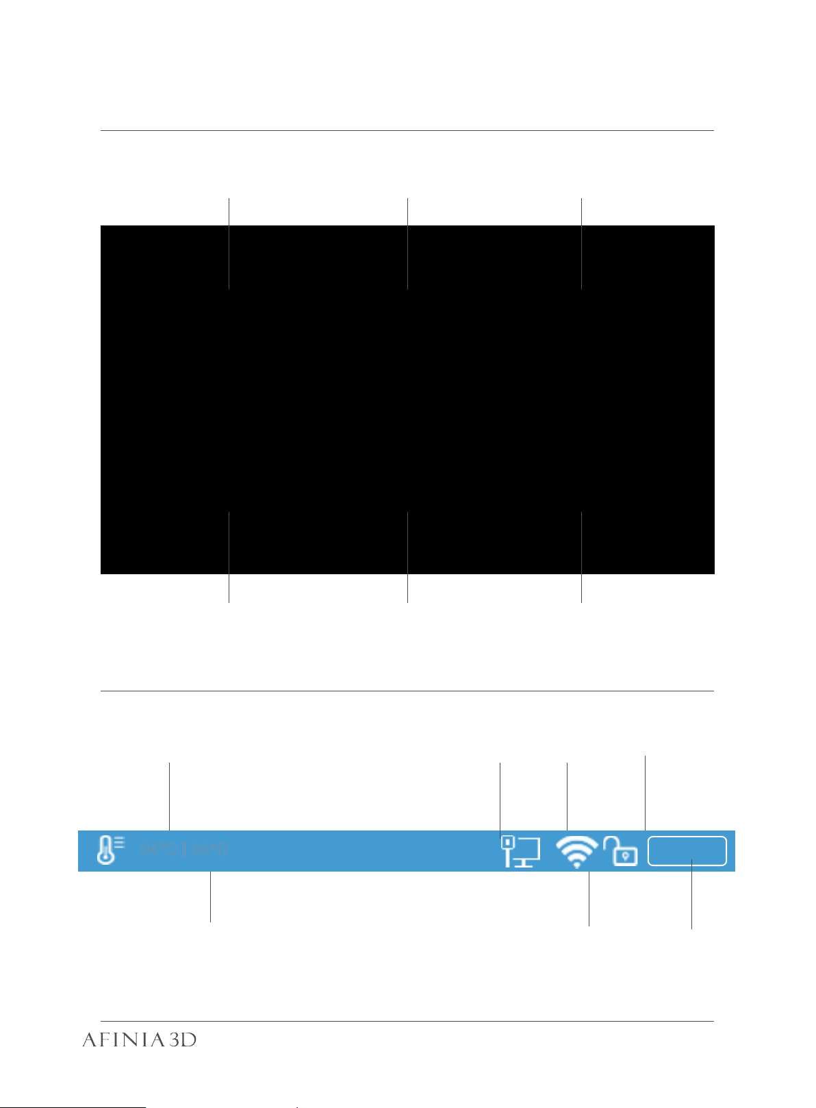
Touch Screen Control 2-7
Change printing
Lorem ipsum
Material
Print a stored project Machine settings
including Wi-Fi
Printer Info, reset to
factory and choose
language
Nozzle Temperature
34°C | 34°C
Platform Temperature
Nozzle Height Detection Initialize the printer
Remaining
LAN Status
Wi-Fi Status
Private
setting status
material
499
Material Type
12
Page 16
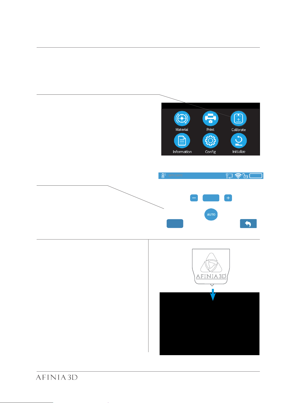
Prepare for Printing - Update Nozzle Height 2-8
Nozzle Height : 125.4mm
The printer was calibrated before leaving the factory, but users
are recommend to update the nozzle height value using the automatic nozzle height detection function on the touch screen
Press “Calibrate” button to enter Nozzle
Height setup page.
Press the “Auto” button to start the
automatic process. Or click “Edit” to
imput the height maually.
34°C | 34°C
499
During nozzle height detection, the
print head nozzle will touch the nozzle
detector to measure the nozzle height.
125.4 mm
Auto
Edit
13
Page 17
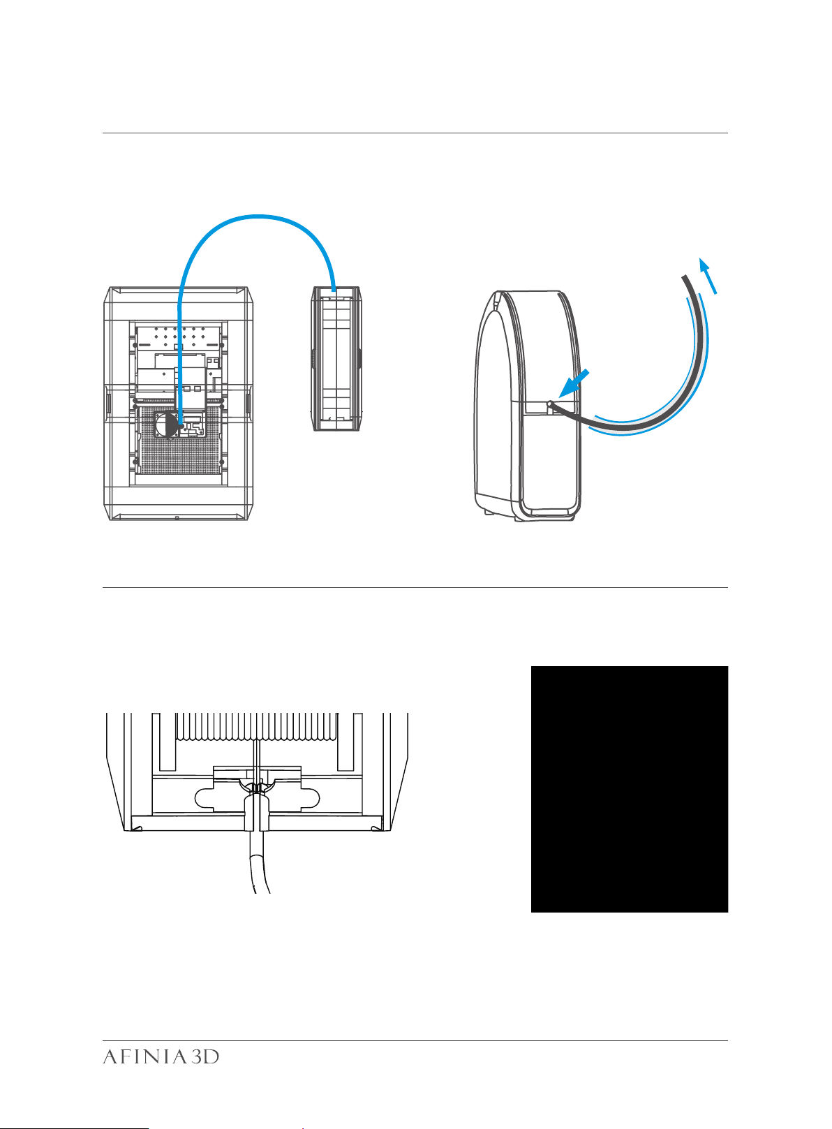
Prepare for Printing - Load Filament 2-9
Install the filament and guiding tube shown in blue.
Front
To printer
Push the guiding tube into the rubber ring as shown below.
14
Page 18
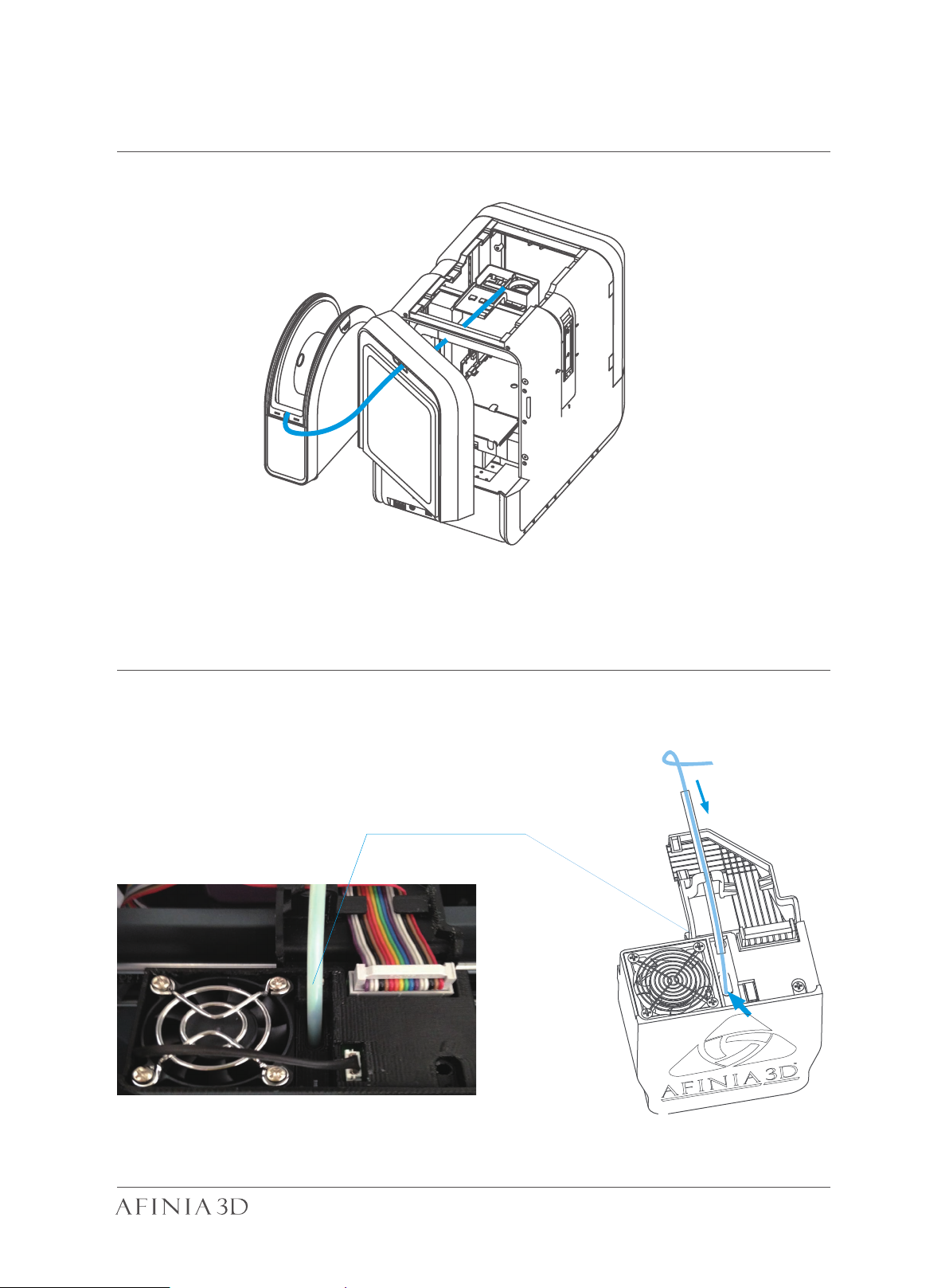
Prepare for Printing - Load Filament 2-10
Back Side
Filament Guiding Tube
insert into the filament
entrance.
From spool
15
Page 19

Prepare for Printing - Load Filament 2-11
Extrude
Withdraw
Information
Calibrate
Print
Material
Initialize
Config
1\ Insert the filament from the spool into guiding tube, arrange the guiding tube as
shown in previous page. Press the Material button on the touch screen.
34°C | 34°C
499
34°C | 34°C
499
2\
S TOP
ABS
499g
3\
2\ Choose the printing material as ABS by press the Wheel button to switch between
different materials input the filament weight by using the +/- buttons.
3\ Click "Extrude." The print head will start to heat up, within 3 minutes. Its tempera-
ture will reach 260°C, then the printer will buzz and the print head will start to extrude.
4\ Gently insert the filament into the
small hole on the print head. The filament
will be fed into the print head automatically
when it reaches the extruder gear inside
the print head.
Guiding Tube
Filament
Filament extrusion
6\ Finally insert the guiding the tube in
to the filament entrance and press the
tube into the holding clip on the print
head mount.
5\ Check the nozzle for plastic extrusion.
If plastic is coming out from the nozzle, that
means the filament is loading correctly and
the printer is ready for printing. (The extrusion will stop automatically.)
Press the guiding tube
into the clamp
Guiding Tube
16
Page 20

Loading a 3D Model 2-12
Load Model Button
17
Page 21

Print a Model 2-13
Make sure printer is connected to computer through USB, Wi-Fi ( go to page 24 for
details about Wi-Fi settings), or an ethernet cable, then load a model.
Set Layer Thickness
Select Infill Type
Select Print Quality/Speed
Nozzle Offset:
This value is permanently effective regarless nozzle height changed or not.
When the Studio software is slicing or sending data to the printer progress displayed on
the status bar on top of the software interface do not unplug the USB cable as this will
disrupt the data transfer and result in a print failure. The USB cable can be unplugged
after the data transfer is finished.
18
Page 22

Printing Progress 2-14
Infill:
Material:
ABS
Layer Thk.:
Quality:
Normal
0.2
Time/ Weight:
1h10m20s/ 135g
File Name:
Cube
Creator:
Tiertime-1
Total T ime/W eight:
1h27m30s/200g
Date:
04-18 12: 11:46
34°C | 34°C
34°C | 34°C
210°C | 70°C
1h10m20s
Time Remaining:
File Name:
ABS, 135g
Material:
Cube
30%
Pressing the “Print” button in the main menu will bring up the Print Job
Current List the same as the one in the software. Clicking the name of
each print job will bring up the detail information of the print job for
print
.
499
Cube
Model- 1
Car
Cylinder
Sphere
Model- 3
Model- 4
Sphere- 1
History
1/ 4
Manage Print Queue
Next Page
Back to Main Menu
499
History
1/ 4
PrintDelete
Start Printing Delet Print Job Back to Print
499
Print Settings
400
StopPause/ Resume ExtrudeWithdraw
19
Page 23

Change Filament During Printing 2-15
210°C | 70°C
1h10m20s
Time Remaining:
File Name:
ABS, 135g
Material:
Cube
30%
210°C | 70°C
1h10m20s
Time Remaining:
File Name:
ABS, 135g
Material:
Cube
30%
400
1. During printing, press the
“Pause” button. The printing
job will be paused.
400
2. When print head stops
moving and the platform lowersPress the “Retract” button
to remove filament.
Press the “Extrude button” to load
the new filament
Press the “resume” button to
resume printing.
After filament is removed, insert new
filament to the print head as described in
page 15.
20
Page 24

Print Queue 2-16
34°C | 34°C
Jeep-2
34°C | 34°C
34°C | 34°C
Infill:
Material:
ABS
Layer Thk.:
Quality:
Normal
0.2
Time/ Weight:
1h10m20s/ 135g
File Name:
Cube
Creator:
Tiertime-1
Total T ime/W eight:
1h27m30s/200g
Date:
04-18 12: 11:46
To start a print,click Print in the touchscreen. Select print job name to
view prints settings and then choose print.
499
Cube
Model- 1
Car
Cylinder
Sphere
Model- 3
Model- 4
Sphere- 1
History
1/ 4
Go to Print Queue
Tiertime Model
Jeep- 1
Car
Sphere
Cube
Sphere
Ring- 1
Choose the print job
499
To view more details of print jobs
Clear
1/ 4
400
Add
Add the print task to current print list to print
21
Page 25
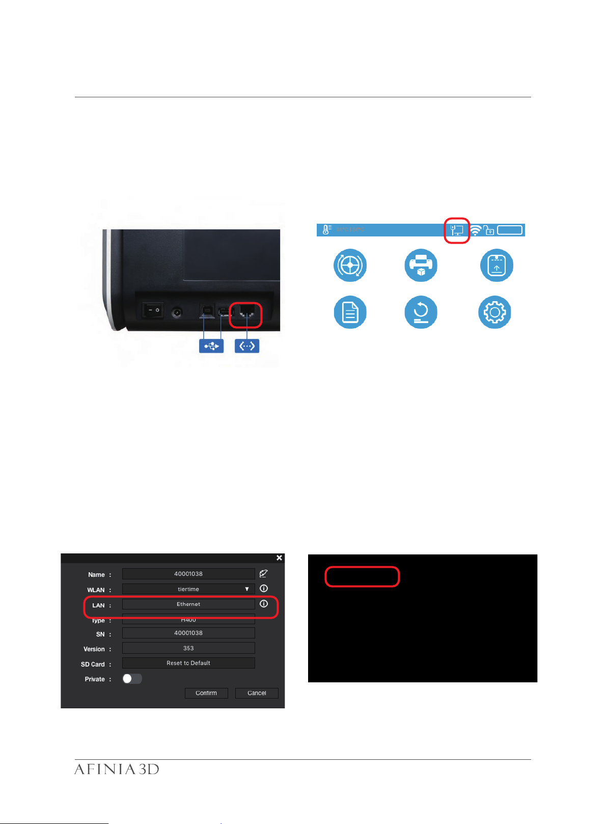
Machine Settings - Ethernet 3-1
Information
Calibrate
Print
Material
Initialize
Config
To connect the Afinia H400+ to ethernet, plug a connected ethernet
cable into the LAN port. Make sure the ethernet icon appereas in
the printer status bar on the touchscreen. Now your printer has
successfully connected to your network.
34°C | 34°C
To edit the ethernet details, go to Settings, click the Printer, choose
the connect printer, choose the “i”, and then toggle on Staic. Now
you can edit the details of the Afinia H400+. Click confirm to save.
499
22
Page 26
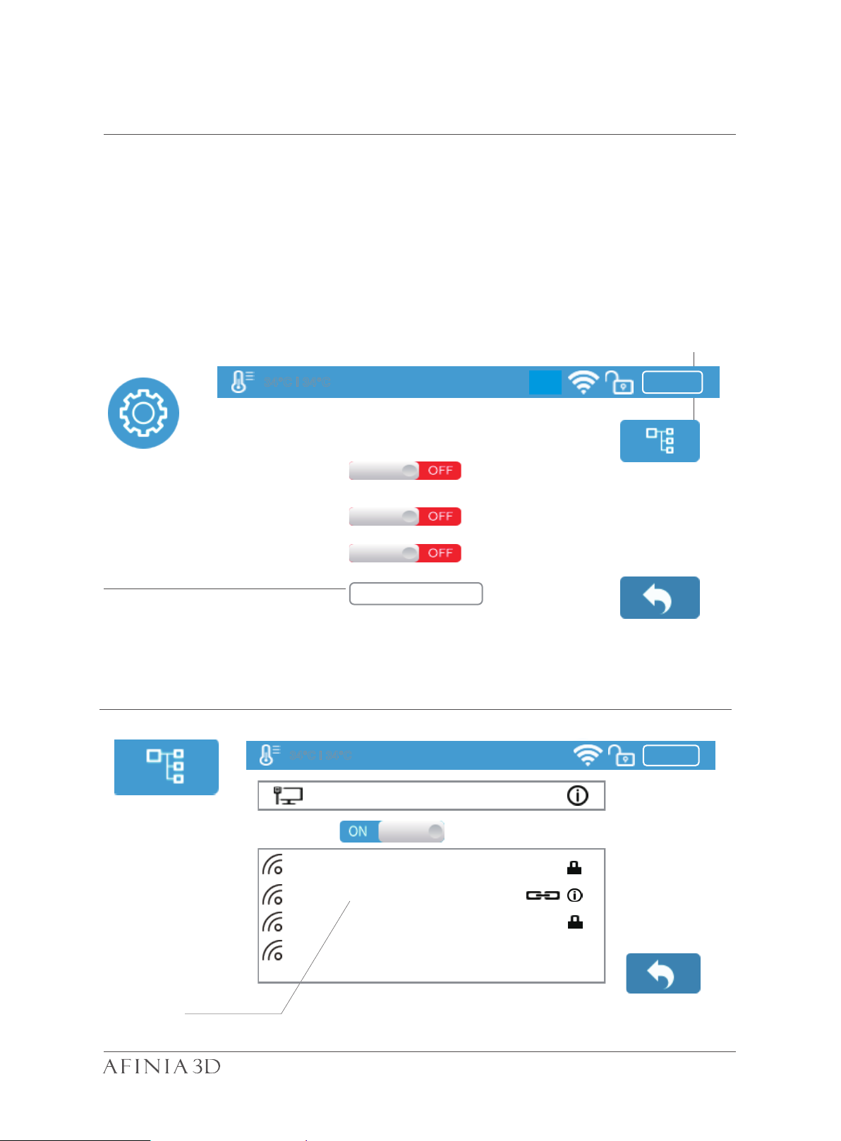
Wi-Fi Setup through Touchscreen 3-2
H400+
Preheat
Sound
Name
Private
Password
34°C | 34°C
Config
Ethernet
Wi-Fi
Your Network
Your Network-04
34°C | 34°C
Connecting to the Afinia H400+ through Wi-Fi requires a Wireless Local Area Net work (WLAN). Computer and printers must connect to the same WIFI network (same
SSID) to communicate.
In order to achieve stable Wi-Fi connection, users are recommended to connect
under a capacious WIFI environment. A crowded network or an area with a large
number different networks are known to cause interruption during data trasnfer.
400
Private setting,
which add password for WIFI
connection.
Select Wi-Fi
123456
400
400
23
Page 27

Network Settings 3-3
34°C | 34°C
Mask
I.P.
Static
Network
Gate
192.168.7.1
DNS
To edit network settings of Wi-Fi networks, click connnected network’s “Information”
button, then toggle on the Static button. The same steps also apply to ethernet connection.
400
Your Network-02
Tiertime
192.168.7.111
255.255.255.255
192.168.1.253
If the user switches on the private function in Wi-Fi setting, a password fieldl
will appear to allow passowrd setup. This password will be required for
Wi-Fi connection to the printer to prevent unathorized usage through Wi-Fi
Please note this is weak protection and that anyone who can access the
printer through USB or touch screen could change the private password.
24
Page 28
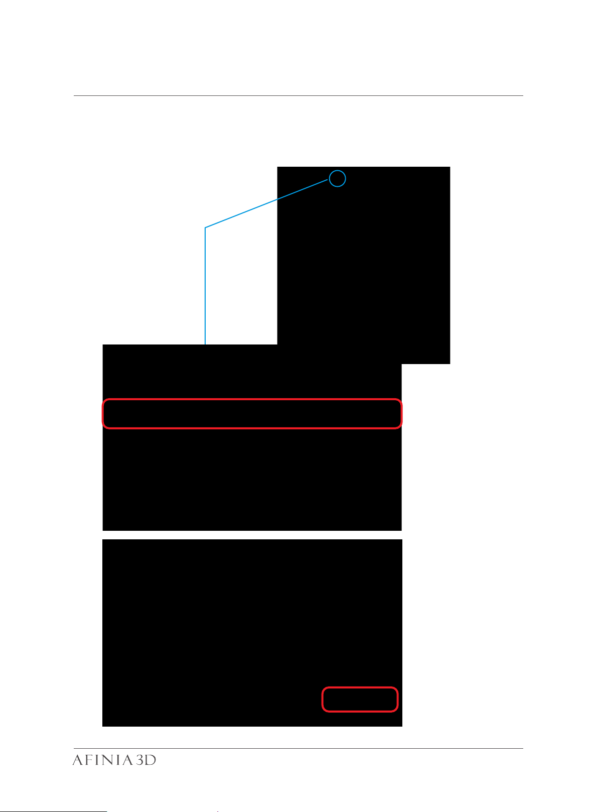
Wi-Fi Setup 3-4
Open Studio on your computer, make sure it connect to the same Wi-Fi
network as the printer. Click “Settings”, find the “Printer” section, then
click”Add printer”.
25
Page 29
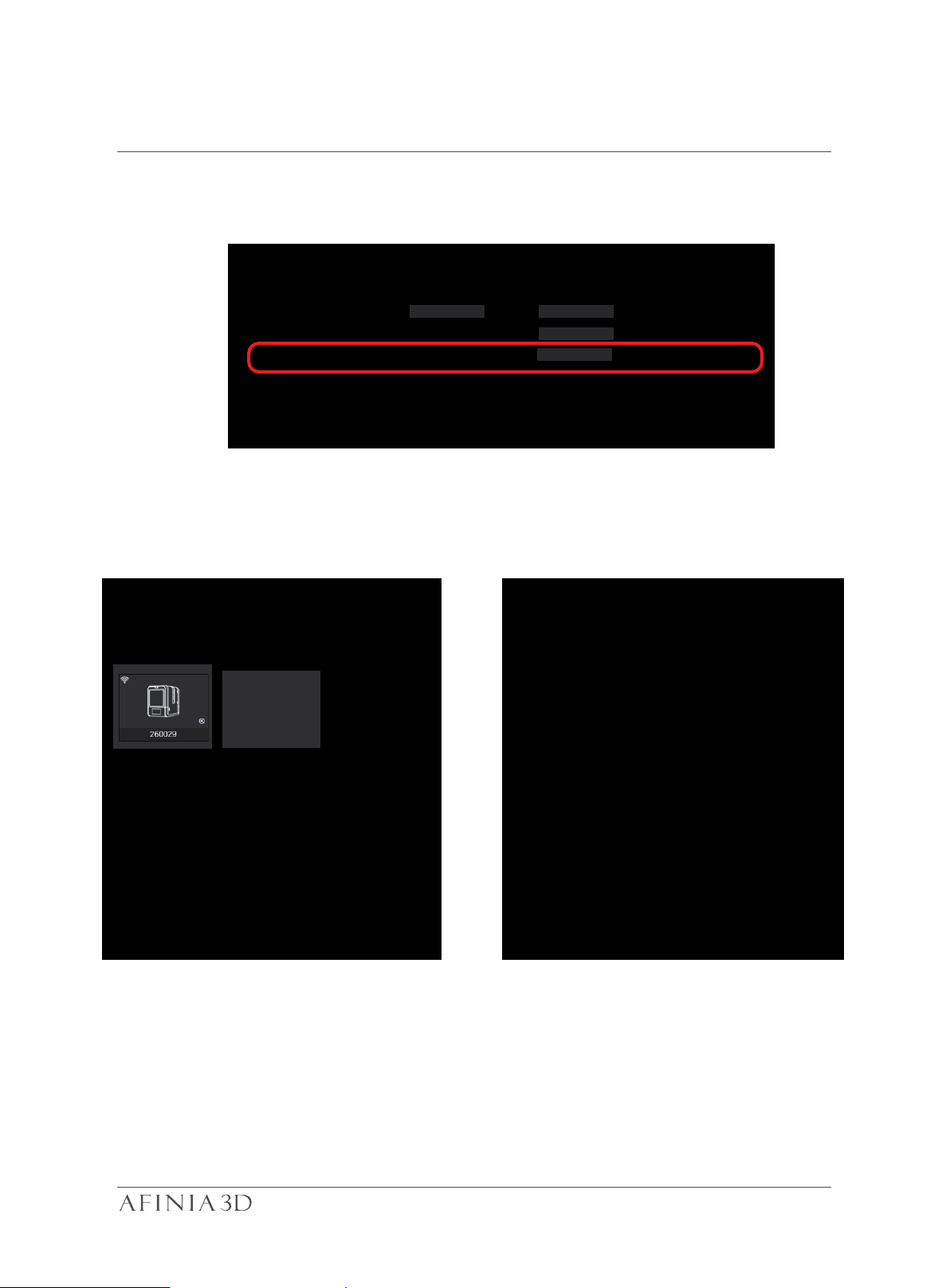
Wi-Fi Setup (Afinia Studio) 3-5
Find the printer in the All printers lists, then click “+” to add the printer. If the
printer not shows up, click “Refresh” to reload the list.
H800+
H400
H400+
The icon of the printer will show up in Printer. Click the printer icon to connect.
A green tick means the printer is connected to the software successfully.
H400+
26
Page 30

Wi-Fi Setup (Afinia Studio) 3-6
You can change the Wi-Fi Network settings in Afinia Studio.
H400+
Your Network-02
H400+
Toggle on “Static”, then to change the IP, Mask, Gate, DNS address. “Con-
firm” to save and finish.
27
Page 31
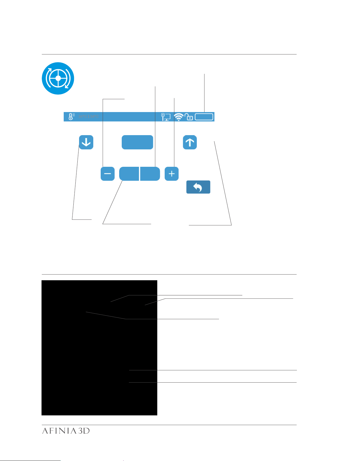
Set Materials (Touch Screen) 3-6
Extrude
Withdraw
current ma-
terial weight
Material Weight
adjustment
34°C | 34°C
Extrude material
Decrease
S TOP
ABS
Change material Withdraw material
499g
Increase
499
Set Materials (Afinia Studio)
Withdraw Filament
Extrude Filament
Select Material
Stop All Actions
Input Material weight
28
Page 32
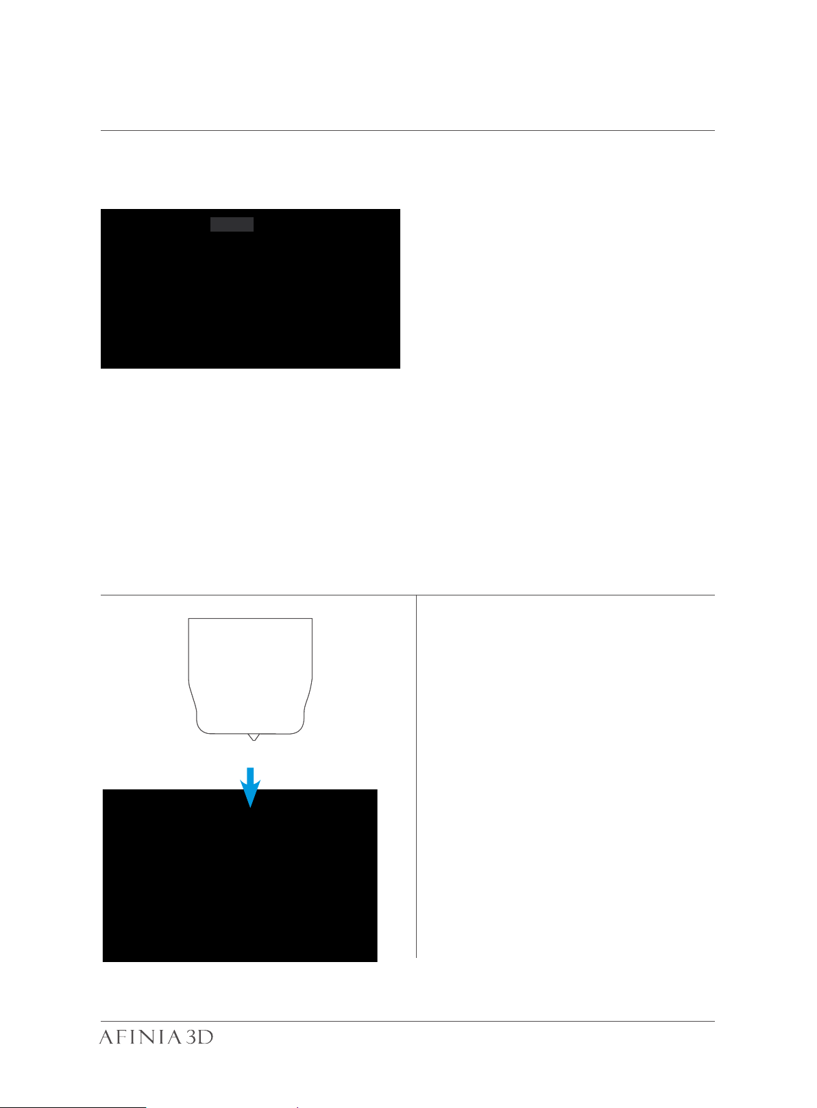
Set Nozzle Height (Afinia Studio) 3-7
For setting nozzle height with touch screen please refer to page 15.
120.90
Open the Calibration panel
At the Nozzle Height section, click “Auto” will initiate the automatic nozzle height detection process.
Clicking +/- button will move the platform up and down, or user could input a specific
value at the text field and click “To” button the move the platform to a specific height.
Clicking “Save” will replace nozzle height value with current platform height.
During nozzle height detec- tion, the
print head nozzle will touch the thin
metal sheet on the detector to make
measurement.
29
Page 33
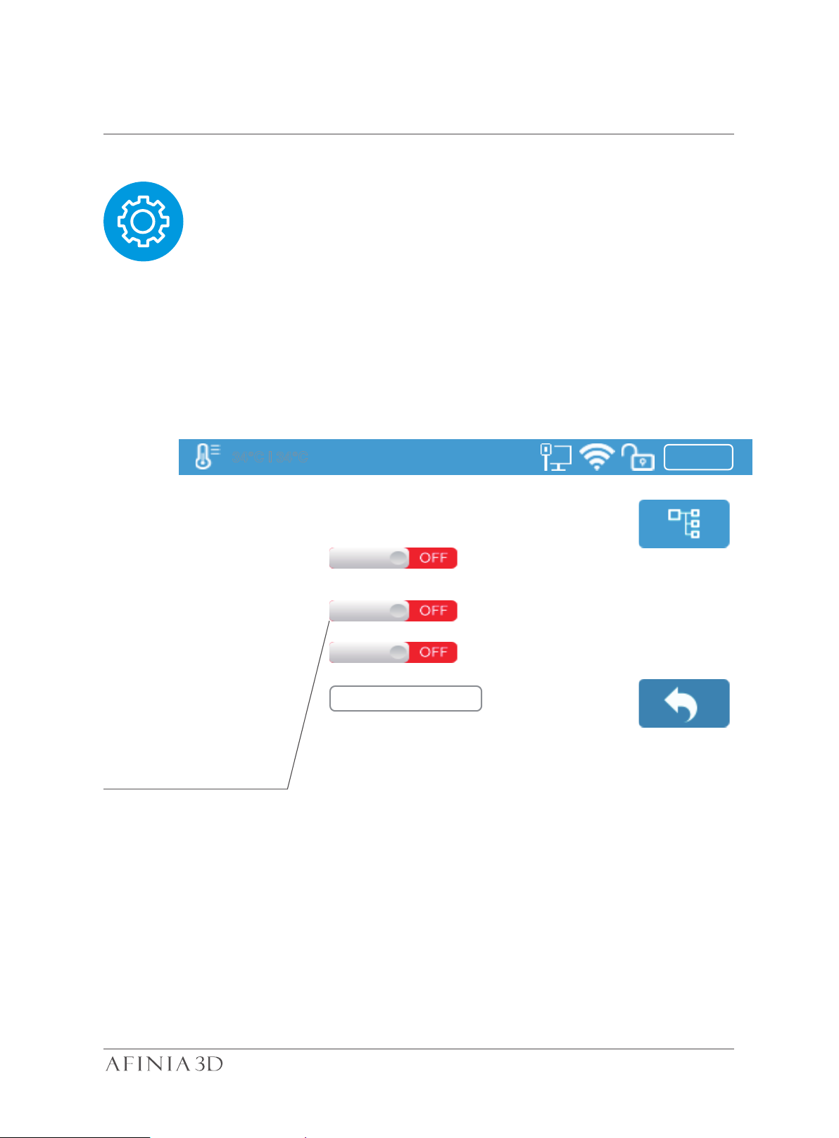
Machine Configuration 3-8
UP mini 2 ES
Preheat
Sound
Name
Private
Password
34°C | 34°C
400
Peheat switch, when turned on,
for every print job, the printer
will first preheat 15min before
proceed to printing.
123456
30
Page 34
Language and Factory Reset 3-9
ABCDEFGHIJKL
1 Kg
0.1h
1.2.3
353
252212
Model:
S.N.:
Lan MAC:
WLAN MAC:
T
T
ABCDEFGHIJKL
Firmware
Screen
34°C | 34°C
H400+
Ver.:
Ver.:
otal T ime:
otal Weight:
Model: current machine model.
S.N.: machine serial number.
Firmware Ver.: shows current firmware version.
499
Reset Language
Screen Ver.: shows current screen version of the printer.
Total Time: total printing time count
Total Weight: total print weight count
Lan MAC: printer’s LAN address
WLAN MAC: printer’s WLAN MAC address.
Reset: The printer’s name, nozzle height, material type to ABS, and material weight will be
500g.
Defult Settings:
Printer’s Name: S.N.
Nozzle Height: 0mm
Material Type: ABS
Material Weight: 500
Language: There are two set of languages to choose from Chinese Simplified and
English.
31
Page 35
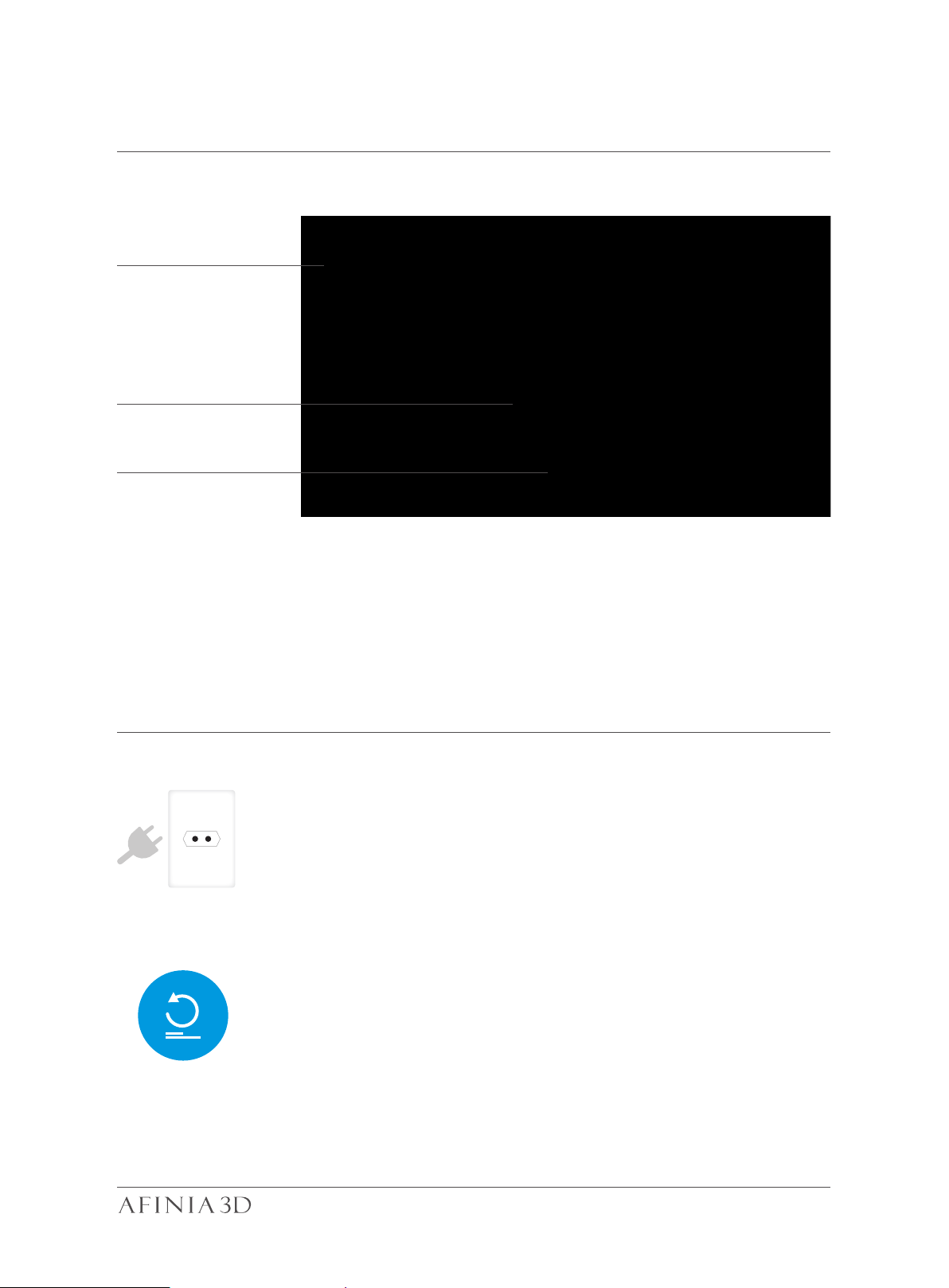
Error Prompts 3-10
Suggested solution,
in this case:
Contact support
Error Message
Error code
Other possible error prompt:
Unplug printer and restart
reinitialize the printer
32
Page 36
Rotating Models (Afinia Studio) 4-1
Choose the model and click the rotate button.
Choose the rotation axis
User could input a specific value
or choose a preset value for rotation.
Alternatively, user could use the rotation
guide to rotate model in real time by holding
and dragging with the mouse.
33
Page 37
Scaling Models (Afinia Studio) 4-2
Choose the model and click the Scale button.
By default the scaling is in all axes.
User could also choose a specific axis for scaling.
User could input a specific scaling
factor or choose a preset value
Click MM or INCH to convert models to
sizes of corresponding units.
Alternatively, user could use the scaling guide
on the model. User could scale
in a specific axis or scale in all directions
by holding and dragging with the mouse.
34
Page 38
Move Model (Afinia Studio) 4-3
Choose the model and click the Move button.
Choose the direction of movement
User could input a specific value or
choose a preset value for distance
of movement.
Alternatively, user could use
the translational guide on the
model to move on the X-Y
plane or a single direction by
holding and dragging the mouse.
35
Page 39

Make Copies (Afinia Studio) 4-4
Choose the model by clicking it (hight lighted),the right-click to bring up the menu and
select copy number.
Repair A Model
1\ If the model contains defective surfac-
es, the software will highlight the surfaces
in red.Click the "more" button to reach
second level menu
2\ Click the x button the repair the mod-
el.The red defective surfaces will resume a
normal color when repaired.
36
Page 40

Merge and Save Models (Afinia Studio) 4-5
1\ Ctrl/CMD click all the models on the
build plate.
2\ The Merge button on the second level
of the adjustment wheel will become available, click to merge the models.
3\ Click the save button to save the
merged models to comptuer.
37
Page 41

Advanced Print Settings
4-6
Surface: the number layers sealing the top and the bottom of the printed object.
Threshold Angle: This determines at which angle the Surface layers will start to print.
Dense: Choose the number of dense layers between support and supported surfaces.
Angle: Determines the angle which support and dense layers are generated.
Area: Determines the minimal area of surface that will be supported, area less than this
vaule will not be supported.
Space: Determines how dense the support will be, the larger the value the less dense
the support.
38
Page 42

Advanced Print Settings 4-7
No Raft: print without raft
No Support: print without support
Stable Support: Support structure will be stronger but less easy to be removed.
Unsolid Model: The software will autofix nonsolid models
Thin Wall: The Software will detect wall thickness that is too thin to print and expand
the feature to a printable size.
Keep Heating: The platform will be heated after print job is completed.
39
Page 43
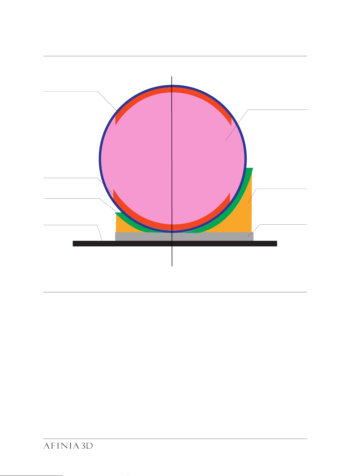
Printing Parameters 4-8
Surface
Infill
Surface
Support
Dense (support)
Print Platform
Support Range: < 30
o
Support Range: < 90
o
Raft
Dense: Solid support structure ensures that the surface being supported retains its
shape and surface finish.
Infill: The inner structure of the printed object. The density of the infill can be adjusted.
Raft: The thick structure that assists with the adhesion of the object to the platform.
Surface: The top and bottom layers of the printed object.
40
Page 44

Manual Calibration 5-1
The 9-button calibration screen shows
the calibration points of the platform.
Clicking on the value next to a number
moves the nozzle to the corresponding
position on the platform. The arrow
buttons move the platform up or down
for manual platform calibration. Before
adjusting the platform calibration, click
the “Reset” button to clear the previous
values. Perform the Nozzle Height
Procedure before setting the Platform
Calibration.
Leave the platform at the Nozzle Height
and click on the value in a numbered
box. Use the up or down keys to move
the platform until the nozzle is just
touching the platform. Do this for each
of the 9 positions then click Save.
The auto buttons triggers automatic
leveling and nozzle height detection.
Auto Level is not available on the H400+.
Moves the platform up/down: click
the +/- buttons to move the platform
up and dow
For sending the platform to a specific height, input the value in the text
eld between + and - and then click
“Move” button.
Click "Set" button user want to save
currently platform height as nozzle
height.
After running the Platform Calibration,
the 9 buttons will have values similar
to those in the figure to the right. If
your values are outside a total range
of 2.00 mm, please attempt the Platform
Calibration again.
NOTE: Having a level platform and correctly set nozzle height are essential for
consistent, error-free printing. If the platform is unlevel or the nozzle height is not
set correctly, the following issues may happen:
- Nozzle jams
- Warping or lifting of prints from the platform
- Prints breaking free from the platform during printing
n.
41
Page 45
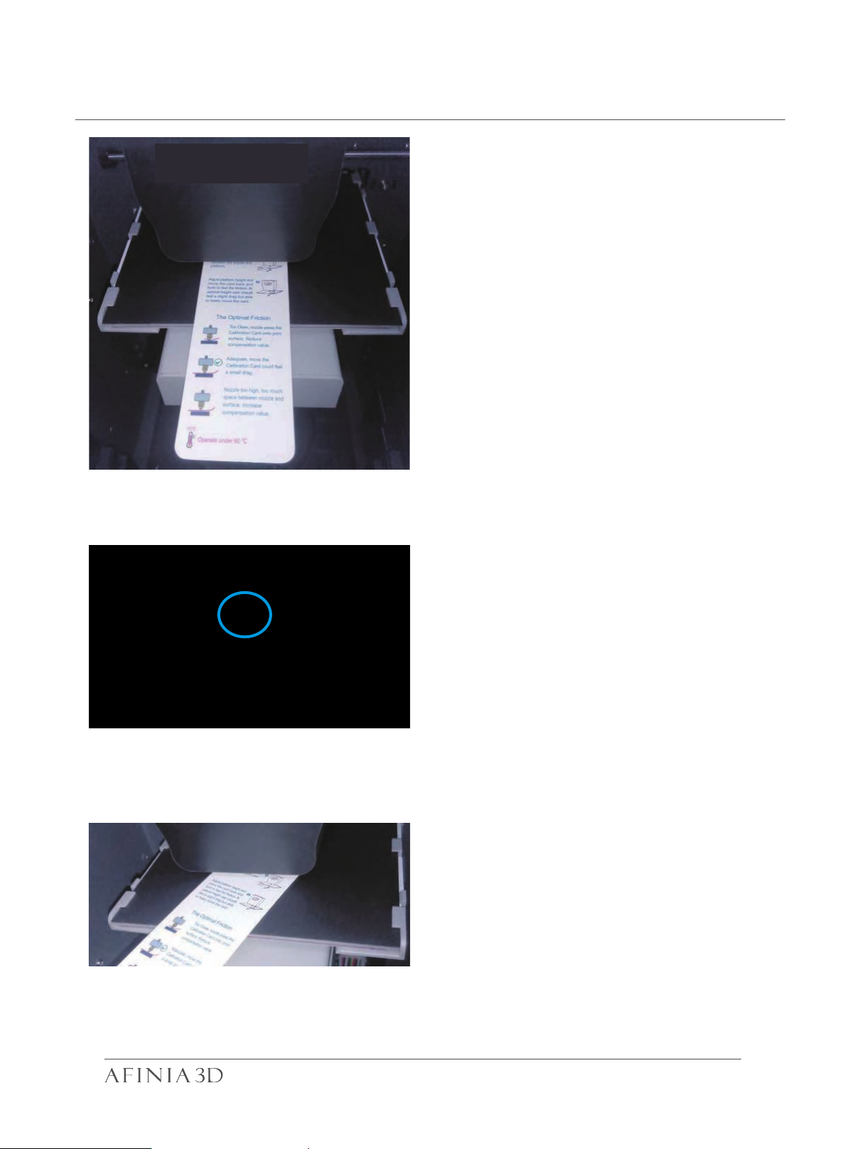
Manual Calibration Nozzle Height 5-2
1\ Initialize the printer
2\ Put the Calibration Card or folded
piece of paper on the platform under
the nozzle.
3\
Move t h e print head to the middle
of the platform by clicking the 5 button.
4\
Raise the platform until it is just
touching the nozzle. Move the paper
between the nozzle and the platform
to see if there is any resistance.
42
Page 46

Model Calibration 5-3
Vertical Calibration, its main
purpose is to ensure all
three axes are perpendicular to each other in order to
guarantee consistent,
high-quality prints.
XYZ Axial Calibration is used to improve dimensional accuracy for a specific model.
When a printed object is found to be deviating from its theoretical dimensions, we can
use this method to correct it and achieve better precision.
43
Page 47
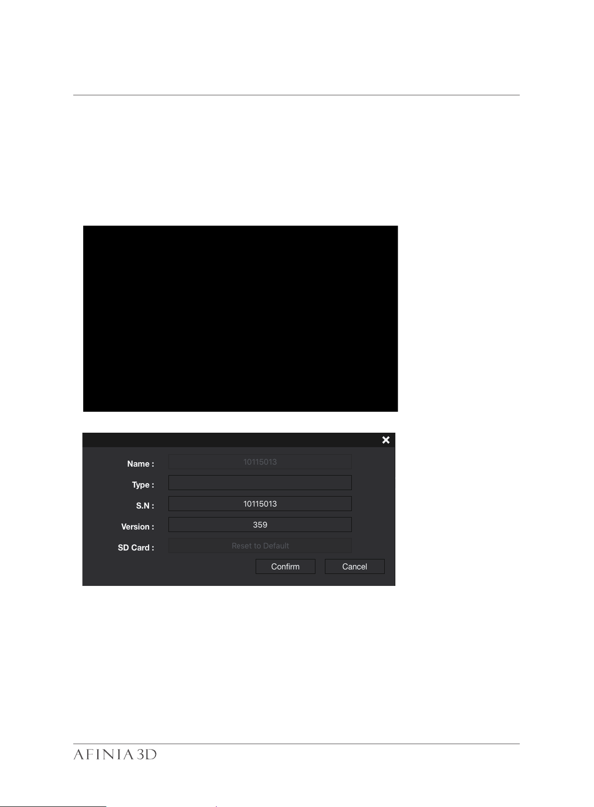
Printer Info 5-4
Printer info will be displayed by clicking the small button on the bottom right hand corner of
the connected printer icon. Information including printer type, serial number and firmware version will be displayed. User could also set a custom name for the printer at
the name field.
H400+
44
Page 48

Software Version and Update 5-5
Check Auto Update to allow the software to inform user of the latest version.
45
Page 49
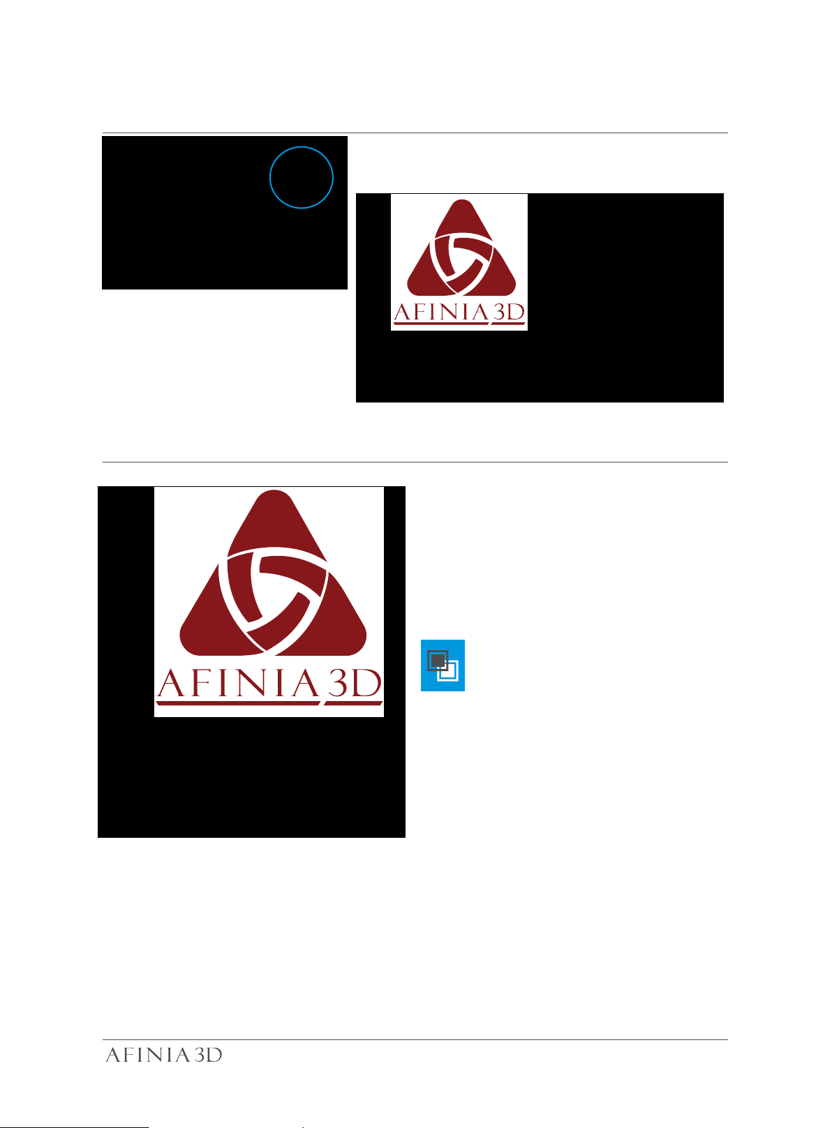
Convert Picture Into 3D Model
Click add picture button and select a picture.
6-1
The Base height determine the thickness of
a flat layer that will hold the picture.
Model Height determine the contrast of the
finally print.
The convert negative button will reverse
the pixel intensity so that user could
choose the picture to be protruding from
or sunken into the base.
46
Page 50
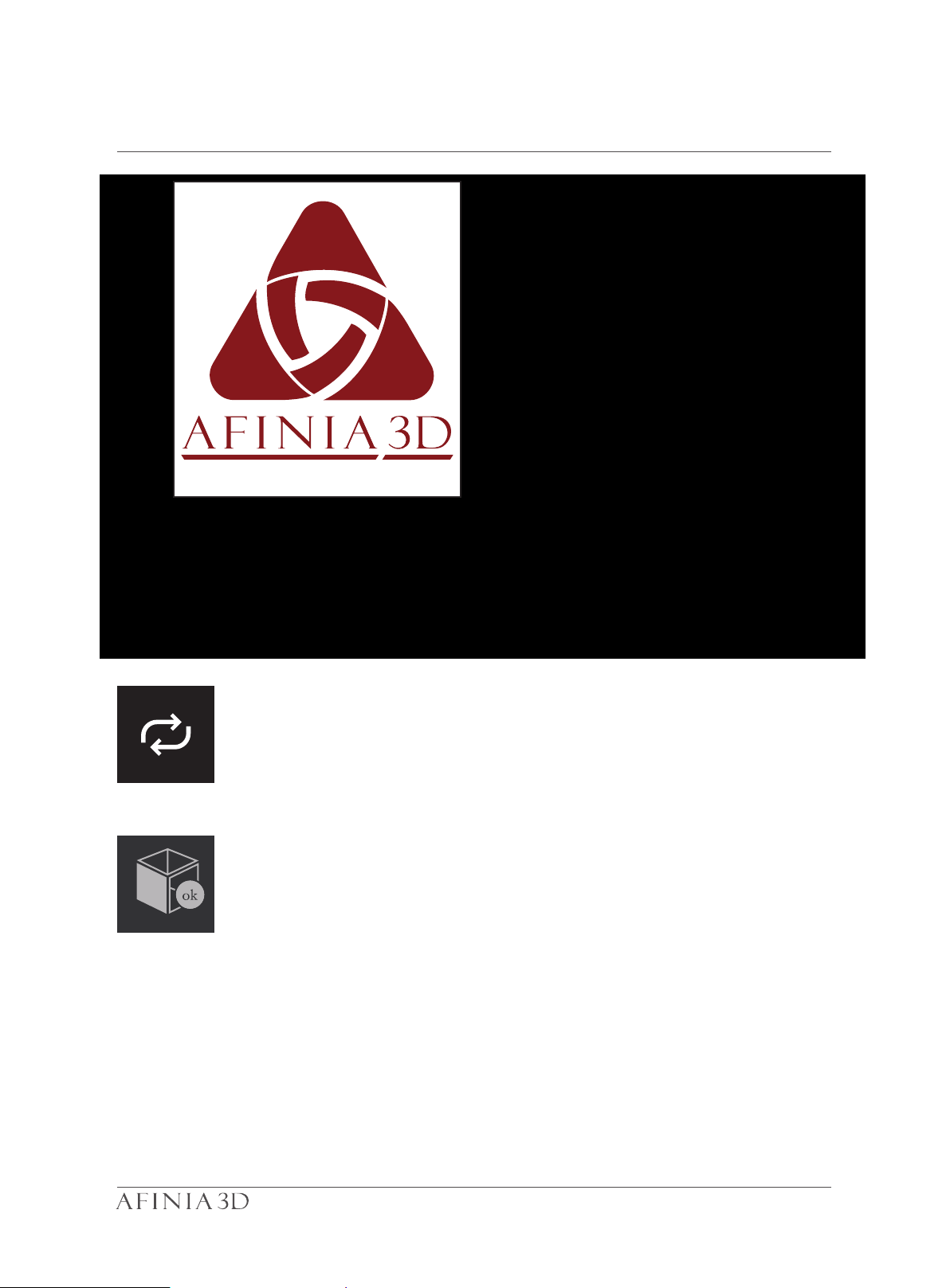
Convert Picture Into 3D Model 2-2
Update 3D model button. This button will convert the modified picture on the left to
a 3D rendering on the right.
OK button sends the 3D rendering to the 3D printing interface for printing.
47
Page 51
Printing Techniques 6-3
1. Ensure accurate nozzle height. If the nozzle height
value is too low, it will cause warping; if it is too high, it will
crash the nozzle into the platform,causing damage and
clogging. You can manually fine-tune the nozzle height
value in the"Calibation"panels.You can try to adjust the
nozzle height value plus or minus 0.1–0.2mm from the
base on previous results.
2. Calibrate the printing platform well. An unleveled platform usually causes warping. Allow enough time for sufficient preheating. Please use the 3DPrint–Preheat function. A well preheated platform is essential for printing
large objects without warping.
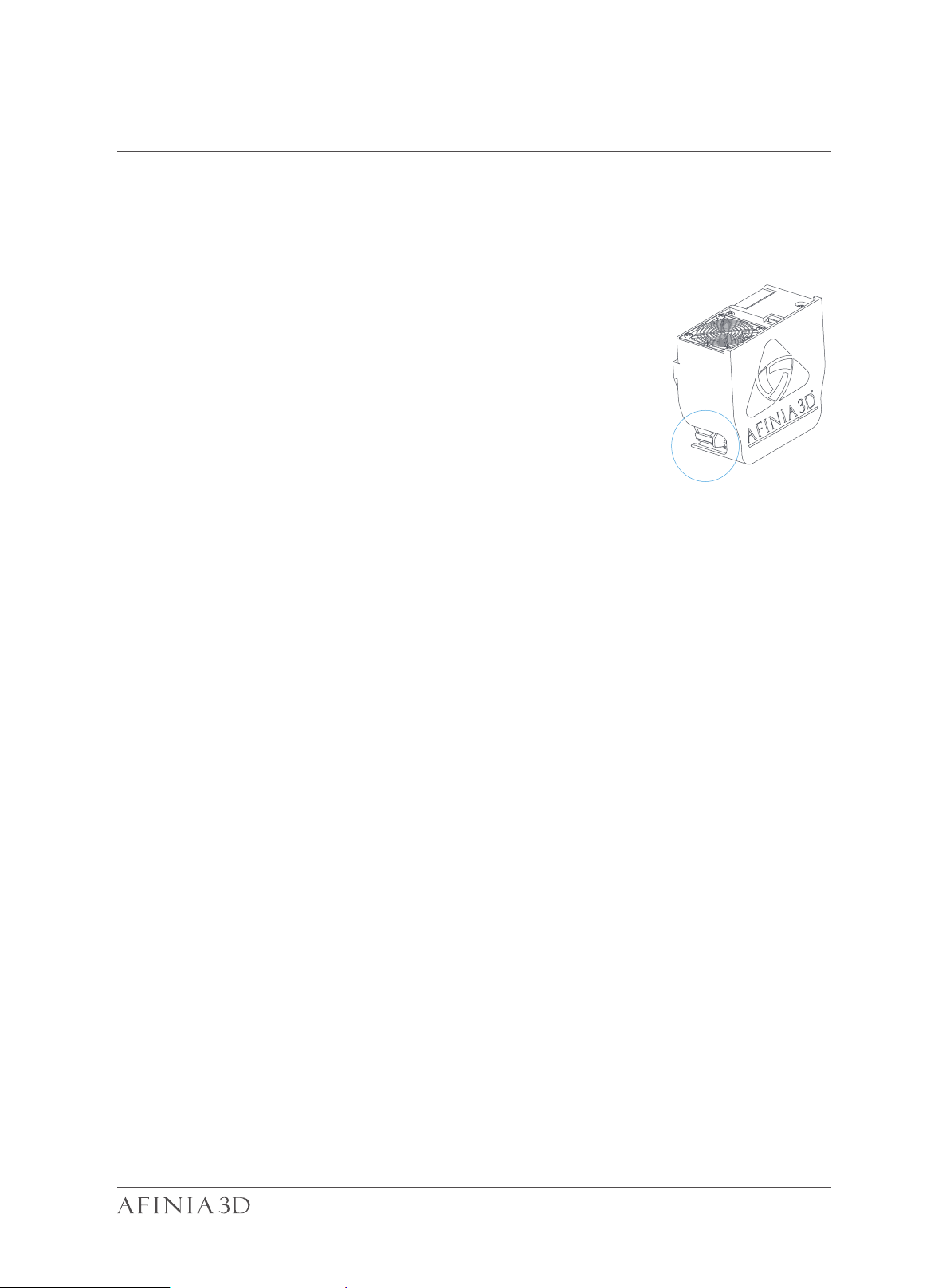
Air Flow Adjustment
3. The airflow on print head is adjustable, slide the air flow
adjustment knob to change the amount of cooling of printed object.Generally the more cooling provided, the better
the print quality. Cooling also help separate from support
and raft. However cooling also encourage warpping,
especially for ABS.
To generalize, PLA can take strong cooling without problem,while ABS should avoid cooling or give little cooling.
For ABS+ medium cooling is recommended.
knob
4. Printing with no raft. It is highly recommended to use
raft for normal printing as it improves adhesion and is
required for leveling compensation. It is turned on by
default, but you can turn it off in the "Print Preference"
panel.
5. Printing with no support. It is possible to print with out
supporting structures.You can turn off support by choosing "No Support" in the "print" setting panel.
48
Page 52
Printer Maintenance - Air Filter Replacement 6-4
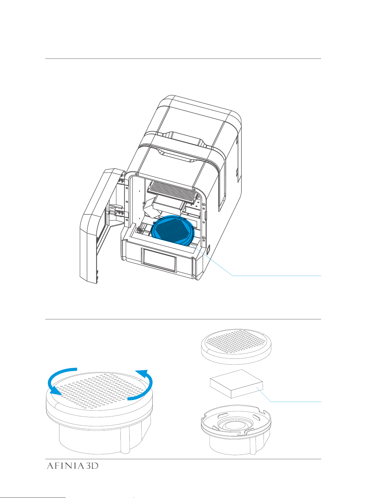
Change air filter for air filatraton unit. It is recommmended to change the filter for
every 300 hours of usage or 6 months.
Front View
Turn counter-clockwise to
open the cap.
Air Filtration Unit
HEPA-Filter
49
Page 53
Print Head Maintenance 6-5
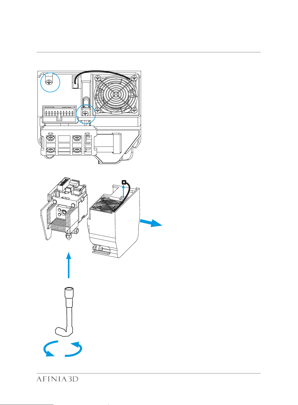
The printhead cover can be removed
after removing two screws.
Heat up the nozzle to printing temperature by using the
extrude function in the maintenace interface.
Nozzle can be removed by using the nozzle wrench
provided. Make sure to stabilize the nozzle heater with
a pair of pliers.
User does not need to remove printhead cover in order to
remove the nozzle.
50
Page 54
Printer Maintenance - remove motherboard cover 6-6
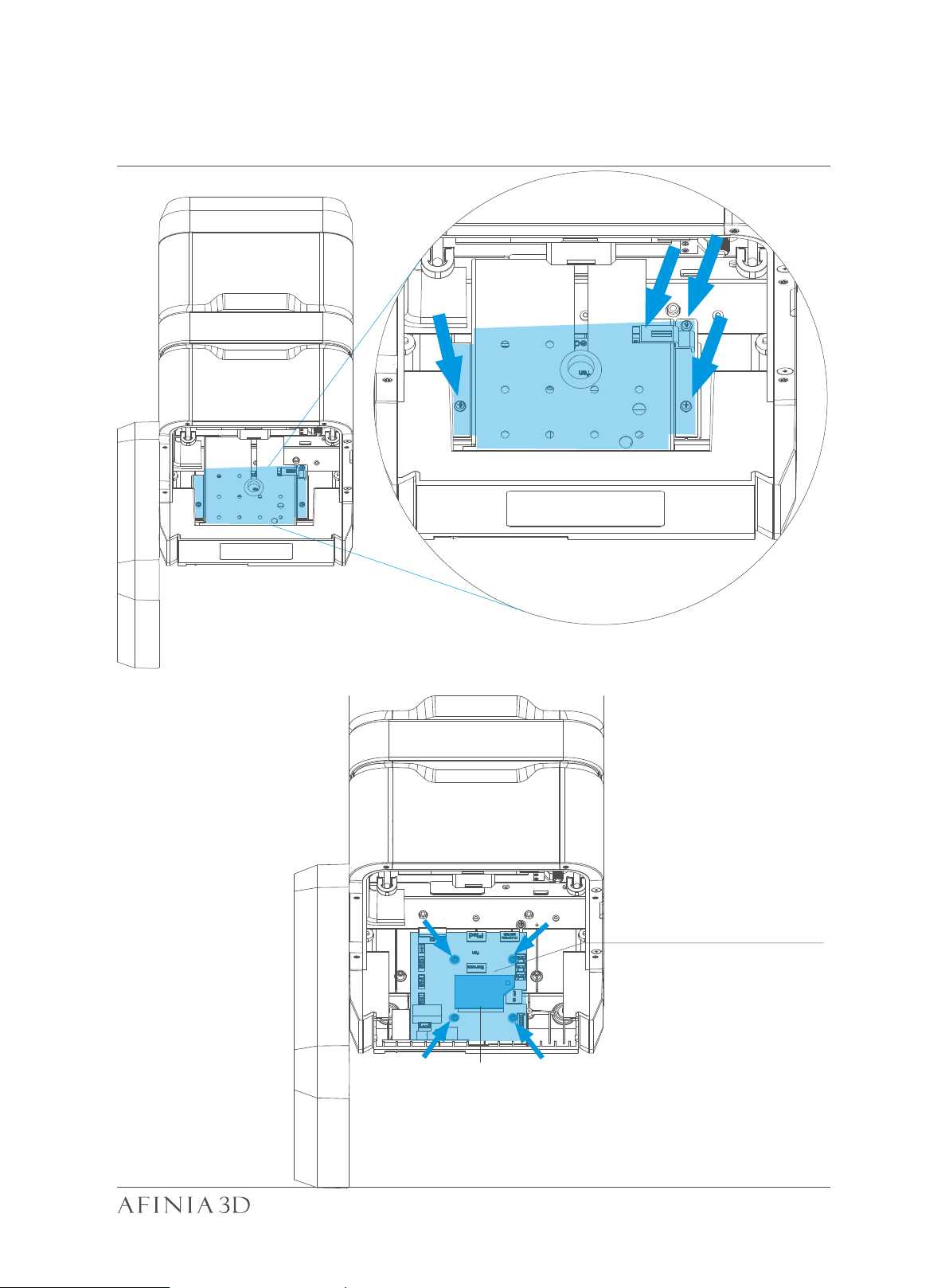
Remove the 3 screws and FFC cable clip on the
mainboard cover.
Mainboard
CPU
51
Page 55

Afinia 3D
8150 Mallory Court, PO BOX 846
Chanhassen, MN 55317
youtube.com/c/Afinia3Dprint
Phone Support: 952-279-2643
Support: [email protected] Web: www.afinia.com
 Loading...