

Aficio K-C3 Service Manual

Model K-C3
Machine Code:
(B245/B276/B277/B268/B269)
SERVICE MANUAL
©Ricoh Company, Ltd.
January 18th, 2006
Subject to change

B245/B276/B277/B268/B269 Service Manual 18-Jan-06
Table of Contents
Read This First .....................................................................................................................1
Safety Notices and Symbols & Abbreviations.................................................................... 1
Important Safety Notices.........................................................................................1
Laser Safety ..................................................................................................................2
Symbols and Abbreviations ............................................................................................... 2
Installation.............................................................................................................................3
Installation Requirements..................................................................................................3
Environment ..................................................................................................................3
Machine Level ...............................................................................................................4
Minimum Space Requirements...................................................................................... 4
Power Requirements .....................................................................................................5
Copier Installation .............................................................................................................6
Power Sockets for Peripherals ......................................................................................6
Accessory Check...........................................................................................................6
Installation Procedure.................................................................................................... 7
Platen Cover Installation ................................................................................................. 11
Accessory Check......................................................................................................... 11
Installation Procedure.................................................................................................. 11
ARDF Installation ............................................................................................................12
Accessory Check.........................................................................................................12
Installation Procedure.................................................................................................. 13
ADF Installation...............................................................................................................16
Accessory Check.........................................................................................................16
Installation Procedure.................................................................................................. 17
Two-tray Paper Tray Unit Installation ..............................................................................20
Accessory Check.........................................................................................................20
Installation Procedure.................................................................................................. 20
One-tray Paper Tray Unit Installation ..............................................................................25
Accessory Check.........................................................................................................25
Installation Procedure.................................................................................................. 25
One-Bin Tray Installation.................................................................................................29
Accessory Check.........................................................................................................29
Installation Procedure.................................................................................................. 29
Anti-condensation Heater Installation.............................................................................. 32
i

B245/B276/B277/B268/B269 Service Manual 18-Jan-06
Tray Heaters ...................................................................................................................33
Upper Tray Heater ....................................................................................................... 33
Lower Tray Heater (Two-tray Model Only)................................................................... 35
Tray Heaters For The Optional Paper Feed Units ....................................................... 36
Key Counter Installation .................................................................................................. 40
GDI Expansion ................................................................................................................ 43
Accessory Check.........................................................................................................43
Installing Expansion Component ................................................................................. 43
Installing Panels and Keys ..............................................................................................45
Preventive Maintenance .....................................................................................................46
PM Tables ....................................................................................................................... 46
How to Reset the PM Counter......................................................................................... 49
Replacement and Adjustment ............................................................................................. 51
General Cautions ............................................................................................................ 51
PCU (Photoconductor Unit) ......................................................................................... 51
Transfer Roller.............................................................................................................51
Scanner Unit................................................................................................................51
Laser Unit ....................................................................................................................52
Fusing Unit ..................................................................................................................52
Paper Feed..................................................................................................................52
Special Tools and Lubricants...........................................................................................53
Exterior Covers & Operation Panel ................................................................................. 54
Rear Cover ..................................................................................................................54
Rear Lower Cover (Two-tray Models Only)..................................................................54
Copy Tray .................................................................................................................... 55
Upper Covers ..............................................................................................................55
Left Cover .................................................................................................................... 56
Front Cover..................................................................................................................56
Front Right Cover ........................................................................................................ 57
Right Rear Cover.........................................................................................................57
Right Door (Duplex Unit (B269/B277)) ........................................................................58
By-pass Tray................................................................................................................ 58
Left Lower Cover (Two-tray Models Only) ...................................................................59
Right Lower Cover (Two-tray Models Only).................................................................59
Platen Cover Sensor ...................................................................................................60
Scanner Unit ...................................................................................................................61
ii

B245/B276/B277/B268/B269 Service Manual 18-Jan-06
Exposure Glass/DF Exposure Glass ........................................................................... 61
Lens Block ................................................................................................................... 62
Lamp Stabilizer Board And Exposure Lamp ................................................................63
Original Width/Length Sensor......................................................................................63
Scanner Motor ............................................................................................................. 65
Scanner Home Position Sensor................................................................................... 66
Adjusting Scanner Positions........................................................................................ 67
Laser Unit........................................................................................................................ 71
Location Of Caution Decal........................................................................................... 71
Toner Shield Glass ...................................................................................................... 71
Laser Unit ....................................................................................................................72
LD Unit.........................................................................................................................73
Polygonal Mirror Motor ................................................................................................73
Laser Unit Alignment Adjustment................................................................................. 74
PCU Section....................................................................................................................76
PCU.............................................................................................................................76
Pick-off Pawls and Toner Density Sensor .................................................................... 77
OPC Drum ................................................................................................................... 78
Charge Roller and Cleaning Brush ..............................................................................79
Cleaning Blade ............................................................................................................ 79
Developer ....................................................................................................................80
After Replacement or Adjustment ................................................................................ 81
Toner Supply Motor ......................................................................................................... 82
Paper Feed Section ........................................................................................................83
Paper Feed Roller .......................................................................................................83
Friction Pad .................................................................................................................84
Paper End Sensor ....................................................................................................... 84
Exit Sensor ..................................................................................................................85
By-Pass Feed Roller and Paper End Sensor............................................................... 86
Registration Roller .......................................................................................................87
By-Pass Paper Size Switch .........................................................................................88
Registration Clutch ...................................................................................................... 89
Registration Sensor .....................................................................................................89
Upper Paper Feed Clutch and By-Pass Feed Clutch ..................................................90
Relay Clutch ................................................................................................................90
Relay Sensor ............................................................................................................... 91
iii

B245/B276/B277/B268/B269 Service Manual 18-Jan-06
Lower Paper Feed Clutch (Two-tray Models Only)......................................................91
Vertical Transport Sensor (Two-tray Models Only) ...................................................... 92
Paper Size Switch .......................................................................................................92
Image Transfer................................................................................................................ 93
Image Transfer Roller .................................................................................................. 93
Image Density Sensor .................................................................................................94
Fusing ............................................................................................................................. 95
Fusing Unit ..................................................................................................................95
Thermistor ...................................................................................................................95
Fusing Lamps .............................................................................................................. 96
Hot Roller Stripper Pawls............................................................................................. 97
Hot Roller..................................................................................................................... 97
Thermostat ..................................................................................................................98
Pressure Roller and Bushings ..................................................................................... 98
NIP Band Width Adjustment ........................................................................................99
Cleaning Roller ..........................................................................................................100
Duplex Unit (Duplex Models B269/B277 Only).............................................................. 101
Duplex Exit Sensor .................................................................................................... 101
Duplex Entrance Sensor............................................................................................ 101
Duplex Inverter Sensor.............................................................................................. 102
Duplex Transport Motor ............................................................................................. 102
Duplex Inverter Motor ................................................................................................ 103
Duplex Control Board ................................................................................................ 103
Other Replacements ..................................................................................................... 104
Quenching Lamp ....................................................................................................... 104
High-Voltage Power Supply Board ............................................................................ 104
BICU (Base-Engine Image Control Unit) ...................................................................105
Main Motor.................................................................................................................105
Rear Exhaust Fan (B269/B277 Only) ........................................................................106
Left Exhaust Fan .......................................................................................................106
PSU (Power Supply Unit) ..........................................................................................107
Gearbox.....................................................................................................................108
Copy Adjustments Printing/Scanning .............................................................................111
Printing .......................................................................................................................111
Scanning.................................................................................................................... 113
ADF Image Adjustment.............................................................................................. 114
iv

B245/B276/B277/B268/B269 Service Manual 18-Jan-06
Troubleshooting ................................................................................................................ 116
Service Call Conditions ................................................................................................. 116
Summary ................................................................................................................... 116
SC Code Descriptions ............................................................................................... 11 7
Electrical Component Defects ....................................................................................... 133
Sensors .....................................................................................................................133
Switches ....................................................................................................................135
Blown Fuse Conditions .................................................................................................137
LED Display ..................................................................................................................138
BICU.......................................................................................................................... 138
Service Tables .................................................................................................................. 139
Service Program Mode .................................................................................................139
How to Enter the SP Mode ........................................................................................139
SP Mode Tables ............................................................................................................141
SP1-XXX (Feed)........................................................................................................141
SP2-XXX (Drum) ....................................................................................................... 144
SP4-XXX (Scanner)................................................................................................... 150
SP5-XXX (Mode) .......................................................................................................156
SP6-XXX (Peripherals).............................................................................................. 159
SP7-XXX (Data Log)..................................................................................................161
SP8-XXX (History).....................................................................................................165
SP9-XXX (Etc.)..........................................................................................................170
Using SP Modes ...........................................................................................................171
Adjusting Registration and Magnification................................................................... 171
ID Sensor Error Analysis (SP 2221)........................................................................... 172
Display APS Data (SP 4301 1) ..................................................................................173
Memory Clear ............................................................................................................ 174
Input Check (SP 5803) ..............................................................................................176
Output Check (SP 5804)............................................................................................179
Serial Number Input (SP 5811) ..................................................................................181
NVRAM Data Upload/Download (SP 5824/5825)...................................................... 181
Firmware Update Procedure...................................................................................... 183
Test Pattern Print (SP 5902 1) ...................................................................................187
Paper Jam Counters (SP 7504)................................................................................. 189
SMC Print (SP 5990) .................................................................................................190
Original Jam History Display (SP 7508).....................................................................190
v

B245/B276/B277/B268/B269 Service Manual 18-Jan-06
ADF APS Sensor Output Display (SP 6901).............................................................. 191
Detailed Section Descriptions........................................................................................... 193
Overview .......................................................................................................................193
Component Layout .................................................................................................... 193
Paper Path................................................................................................................. 194
Drive Layout ..............................................................................................................195
Board Structure ............................................................................................................. 196
Block Diagram ........................................................................................................... 196
BICU (Base Engine and Image Control Unit)............................................................. 197
SBU (Sensor Board Unit)...........................................................................................197
Copy Process Overview................................................................................................ 198
Scanning .......................................................................................................................200
Overview....................................................................................................................200
Scanner Drive............................................................................................................201
Original Size Detection in Platen Mode ..................................................................... 202
Image Processing .........................................................................................................205
Overview....................................................................................................................205
SBU (Sensor Board Unit)...........................................................................................206
IPU (Image Processing Unit) ..................................................................................... 207
Video Control Unit (VCU)........................................................................................... 218
Laser Exposure ............................................................................................................. 219
Overview....................................................................................................................219
Auto Power Control (APC).........................................................................................220
LD Safety Switch ....................................................................................................... 221
Photoconductor Unit (PCU)...........................................................................................222
Overview....................................................................................................................222
Drive ..........................................................................................................................223
Drum Charge................................................................................................................. 224
Overview....................................................................................................................224
Charge Roller Voltage Correction.............................................................................. 225
ID Sensor Pattern Production Timing ........................................................................ 226
Drum Charge Roller Cleaning.................................................................................... 226
Development ................................................................................................................. 227
Overview....................................................................................................................227
Drive ..........................................................................................................................228
Developer Mixing....................................................................................................... 228
vi

B245/B276/B277/B268/B269 Service Manual 18-Jan-06
Development Bias .....................................................................................................229
Toner Supply..............................................................................................................230
Toner Supply Mechanism ..........................................................................................231
Toner Density Control ................................................................................................231
Toner Supply in Abnormal Sensor Conditions............................................................235
Toner Near End/End Detection and Recovery ...........................................................236
Drum Cleaning and Toner Recycling ............................................................................. 238
Drum Cleaning........................................................................................................... 238
Toner Recycling ......................................................................................................... 239
Paper Feed ...................................................................................................................240
Overview....................................................................................................................240
Paper Feed Drive Mechanism ................................................................................... 241
Paper Feed and Separation Mechanism ...................................................................241
Paper Lift Mechanism................................................................................................ 242
Paper End Detection .................................................................................................242
Paper Size Detection................................................................................................. 243
Side Fences............................................................................................................... 245
Paper Registration..................................................................................................... 245
Image Transfer and Paper Separation ..........................................................................247
Overview....................................................................................................................247
Image Transfer Current Timing..................................................................................248
Transfer Roller Cleaning............................................................................................249
Paper Separation Mechanism ...................................................................................250
Image Fusing and Paper Exit ........................................................................................ 251
Overview....................................................................................................................251
Fusing Unit Drive and Release Mechanism...............................................................252
Fusing Entrance Guide Shift......................................................................................253
Pressure Roller..........................................................................................................254
Fusing Temperature Control ......................................................................................254
Overheat Protection................................................................................................... 256
Duplex Unit....................................................................................................................258
Overall .......................................................................................................................258
Drive Mechanism.......................................................................................................259
Basic operation..........................................................................................................259
Feed In and Exit Mechanism ..................................................................................... 262
Energy Saver Modes of Basic Machines....................................................................... 263
vii

B245/B276/B277/B268/B269 Service Manual 18-Jan-06
Overview....................................................................................................................263
AOF ...........................................................................................................................264
Timers........................................................................................................................264
Recovery ...................................................................................................................264
Energy Saver Modes of GDI Machines ......................................................................... 265
Overview....................................................................................................................265
AOF ...........................................................................................................................266
Timers........................................................................................................................266
Recovery ...................................................................................................................266
Specifications....................................................................................................................267
General Specifications .................................................................................................. 267
Supported Paper Sizes ................................................................................................. 271
Original Size Detection ..............................................................................................271
Paper Feed and Exit.................................................................................................. 273
Machine Configuration ..................................................................................................276
Optional Equipment....................................................................................................... 278
ARDF......................................................................................................................... 278
ADF ........................................................................................................................... 278
One-Tray Paper Tray Unit..........................................................................................279
Two-Tray Paper Tray Unit .......................................................................................... 280
One-Bin Tray ............................................................................................................. 280
viii

B245/B276/B277/B268/B269 Service Manual 18-Jan-06
Read This First
Safety Notices and Symbols & Abbreviations
Important Safety Notices
Prevention of Physical Injury
1. Before disassembling or assembling parts of the copier and peripherals,
make sure that the power cord is unplugged.
2. The wall outlet should be near the copier and easily accessible.
3. Note that some components of the copier and the paper tray unit are
supplied with electrical voltage even if the main power switch is turned off.
4. If a job has started before the copier completes the warm-up or initializing
period, keep hands away from the mechanical and electrical components
because the starts making copies as soon as the warm-up period is
completed.
5. The inside and the metal parts of the fusing unit become extremely hot while
the copier is operating. Be careful to avoid touching those components with
your bare hands.
Health Safety Conditions
Toner and developer are non-toxic, but if you get either of them in your eyes by accident, it
may cause temporary eye discomfort. Try to remove with eye drops or flush with water as first
aid. If unsuccessful, get medical attention.
Observance of Electrical Safety Standards
The copier and its peripherals must be installed and maintained by a customer service
representative who has completed the training course on those models.
Safety and Ecological Notes for Disposal
1. Do not incinerate toner bottles or used toner. Toner dust may ignite
suddenly when exposed to an open flame.
2. Dispose of used toner, developer, and organic photoconductors in
accordance with local regulations. (These are non-toxic supplies.)
3. Dispose of replaced parts in accordance with local regulations.
1

B245/B276/B277/B268/B269 Service Manual 18-Jan-06
Laser Safety
The Center for Devices and Radiological Health (CDRH) prohibits the repair of laser-based
optical units in the field. The optical housing unit can only be repaired in a factory or at a
location with the requisite equipment. The laser subsystem is replaceable in the field by a
qualified Customer Engineer. The laser chassis is not repairable in the field. Customer
engineers are therefore directed to return all chassis and laser subsystems to the factory or
service depot when replacement of the optical subsystem is required.
Use of controls, or adjustment, or performance of procedures other than
those specified in this manual may result in hazardous radiation exposure.
WARNING FOR LASER UNIT
WARNING: Turn off the main switch before attempting any of the procedures in the
Laser Unit section. Laser beams can seriously damage your eyes.
CAUTION MARKING:
Symbols and Abbreviations
This manual uses several symbols and abbreviations. The meaning of those symbols and
abbreviations are as follows:
See or Refer to
Clip ring
Screw
Connector
SEF Short Edge Feed
LEF Long Edge Feed
2
B245/B276/B277/B268/B269 Service Manual 18-Jan-06
Installation
Installation Requirements
Before installing options, please do the following:
If there is a printer option in the machine, print out all data in the printer buffer.
Turn off the main switch and disconnect the power cord, the telephone line, and
the network cable.
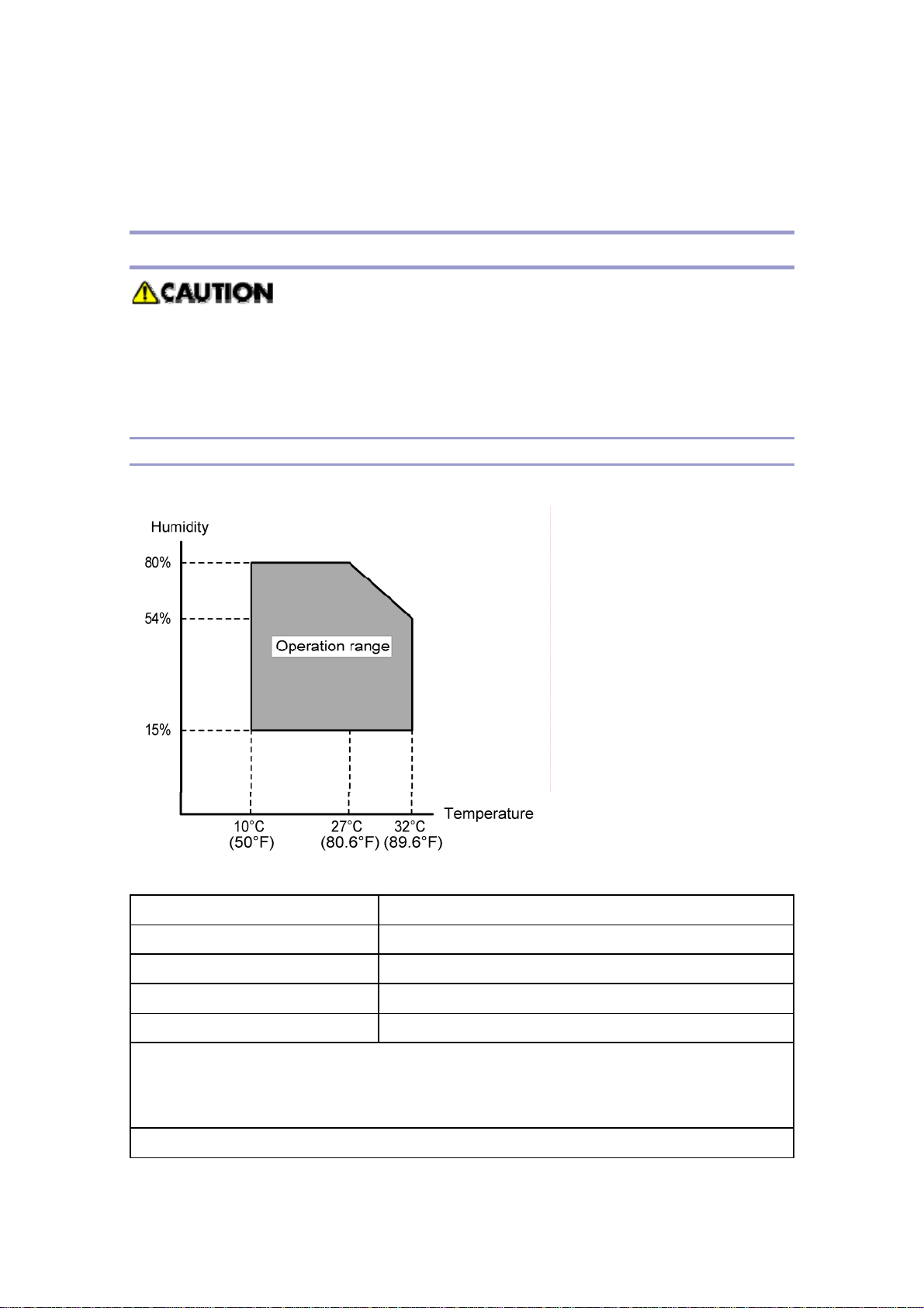
Environment
–Temperature and Humidity Chart–
Temperature Range: 10C to 32C (50F to 89.6F)
Humidity Range: 15% to 80% RH
Ambient Illumination: Less than 1,500 lux (do not expose to direct sunlight)
Ventilation: 3 times/hr/person or more
Ambient Dust: Less than 0.075 mg/m3 (2.0 x 10⁻⁶ oz/yd3)
Avoid areas exposed to sudden temperature changes:
1) Areas directly exposed to cool air from an air conditioner.
2) Areas directly exposed to heat from a heater.
Do not place the machine in areas where it can get exposed to corrosive gases.
3
B245/B276/B277/B268/B269 Service Manual 18-Jan-06
Do not install the machine at any location over 2,000 m (6,500 ft.) above sea level.
Place the machine on a strong and level base. (Inclination on any side should be no
more than 5 mm.)
Do not place the machine where it is subjected to strong vibrations.
Machine Level
Front to back: Within 5 mm (0.2") of level
Right to left: Within 5 mm (0.2") of level
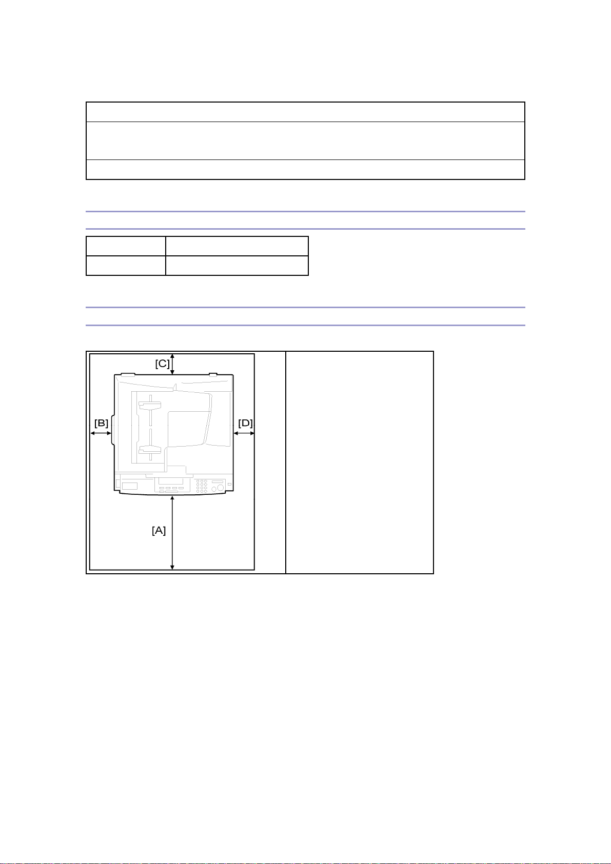
Minimum Space Requirements
Place the copier near the power source, providing clearance as shown:
A (front): 750 mm (30")
B (left): 150 mm (6")
C (rear): 50 mm (2")
D (right): 250 mm (10")
The recommended 750 mm front space is sufficient to allow the paper tray to be pulled out.
Additional front space is required to allow operators to stand at the front of the machine.
4

B245/B276/B277/B268/B269 Service Manual 18-Jan-06
Power Requirements
Make sure that the wall outlet is near the machine and easily accessible. After.
completing installation, make sure the plug fits firmly into the outlet.
Avoid multi-wiring.
Be sure to ground the machine
Input voltage:
North and South America, Taiwan: 110 – 120 V, 60 Hz, 12 A
Europe, Asia: 220 – 240 V, 50/60 Hz, 7 A
5
B245/B276/B277/B268/B269 Service Manual 18-Jan-06
Copier Installation
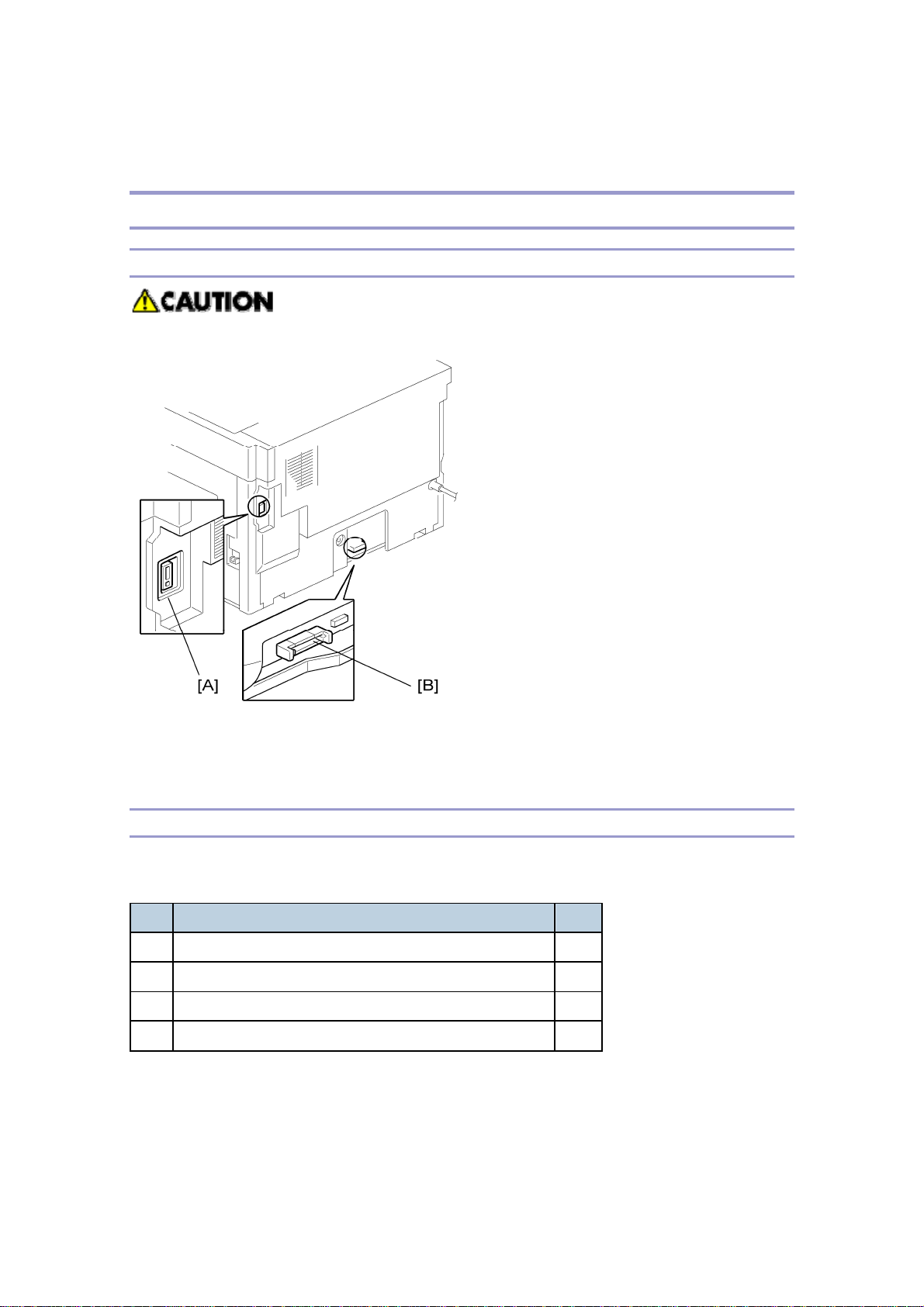
Power Sockets for Peripherals
Make sure to plug the cables into the correct sockets.
[A]: Socket for ADF/ARDF (Rated voltage output max. DC24 V)
[B]: Socket for paper tray unit (Rated voltage output max. DC24 V)
Accessory Check
Check that you have the accessories in this list.
Basic Machines
No. Description Q’ty
1 NECR-English /Multi-language (-17, -27,-19, -29) 1
2 EU Safety Sheet (-27, -22,-24, -26) 1
3 Laser Decal (-27, -22,-24, -26, -19, -28, -29) 1
4 Model Name Plate (-22,-29) 1
6
B245/B276/B277/B268/B269 Service Manual 18-Jan-06
GDI Machines
No. Description Q’ty
1 NECR-English /Multi-language (-19, -29) 1
2 Laser Decal (-19, -29) 1
3 Model Name Plate (-19, -29) 1
4 Operating Instructions (-19, -29) 1
5 General Setting Guide (-19, -29) 1
6 Copy Reference (-19, -29) 1
7 Printer/Scanner Reference (-19, -29) 1
8 Network Reference (-19, -29) 1
9 Quick Guide Copy Edition (-19, -29) 1
10 Quick Guide Printer/Scanner Edition (-19, -29) 1
11 Manual for this machine (-19, -29) 1
12 Safety Information (-19, -29) 1
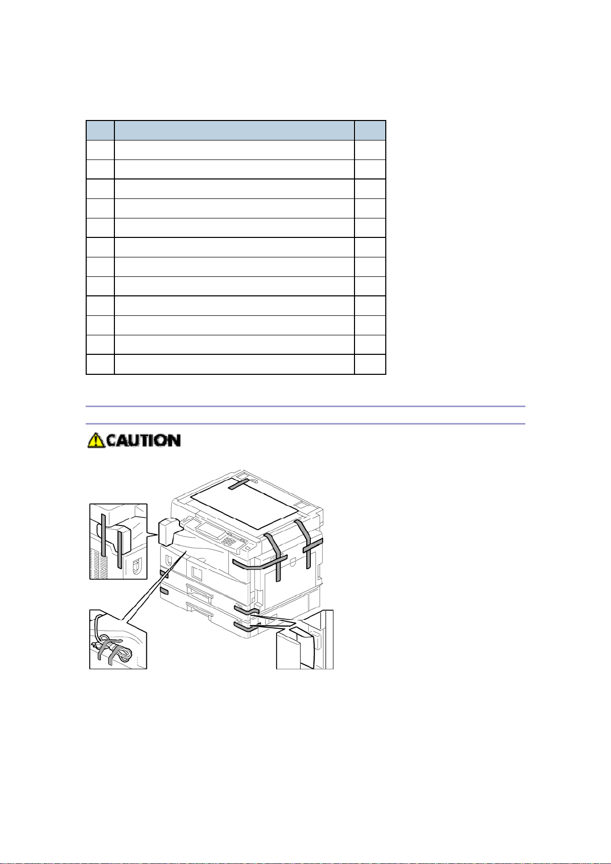
Installation Procedure
Unplug the machine power cord before starting the following procedure.
1. Remove filament tape and other padding.
7
B245/B276/B277/B268/B269 Service Manual 18-Jan-06
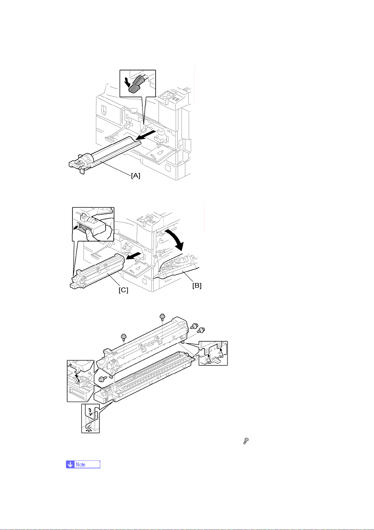
2. Open the front door and remove the toner bottle holder [A]
3. Open the right door [B], and remove the PCU (photoconductor unit) [C].
4. Separate the PCU into the upper part and the lower part (
5. Put a sheet of paper on a level surface and place the upper part on it.
x 5).
8
B245/B276/B277/B268/B269 Service Manual 18-Jan-06
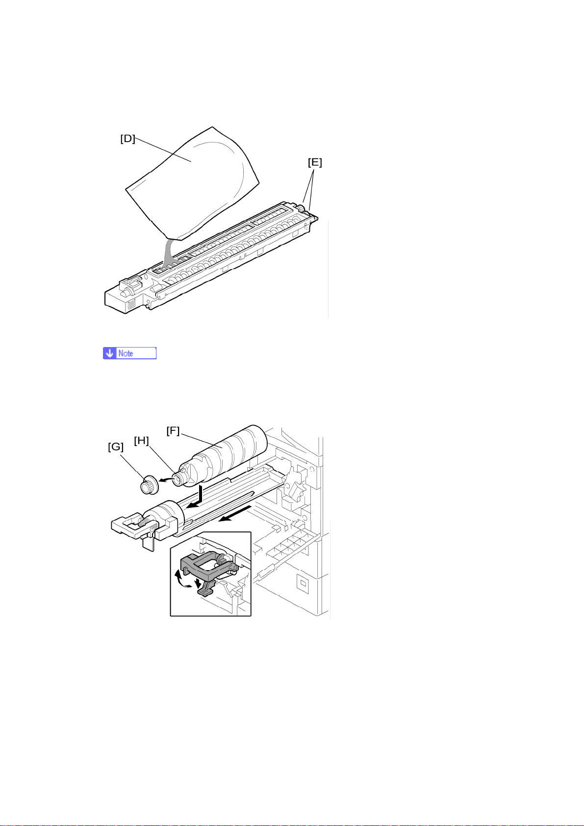
This prevents foreign material from getting on the sleeve rollers
6. Distribute a pack of developer [D] to all openings equally.
Do not spill the developer on the gears [E]. If you have spilled it, remove the
developer by using a magnet or magnetized screwdriver.
Do not turn the gear [E] too much. The developer may spill.
7. Reassemble the PCU and reinstall it.
8. Shake the toner bottle [F] several times. (Do not remove the bottle cap [G] before
you shake the bottle.)
9. Remove the bottle cap [G] and install the bottle on the holder. (Do not touch the
inner cap [H].)
10. Set the holder (with the toner bottle) in the machine.
9
B245/B276/B277/B268/B269 Service Manual 18-Jan-06
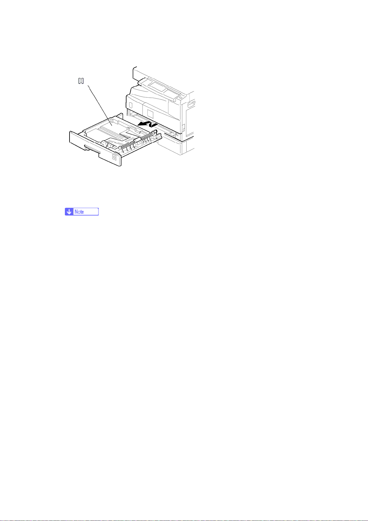
11. Pull out the paper tray [I] and turn the paper size dial to the appropriate size.
Adjust the positions of the end and side guides.
To move the side guides, release the green lock on the rear side guide.
12. Install the optional ARDF, ADF, or platen cover.
13. Plug in the main power cord and turn on the main switch.
14. Activate the SP mode and execute "Devlpr Initialize" (SP 2214 1).
15. Wait until the message "Completed" shows (about 45 seconds).
16. Activate the User Tools and select the menu "Language."
17. Specify a language. This language is used for the operation panel.
18. Load the paper in the paper tray and make a full size copy, and make sure the
side-to-side and leading edge registrations are correct.
10

B245/B276/B277/B268/B269 Service Manual 18-Jan-06
Platen Cover Installation
Accessory Check
Check that you have the accessories indicated below.
No. Description Q’ty
1 Stepped Screw 2
Installation Procedure
Unplug the machine power cord before starting the following procedure.
Install the platen cover (
x 2).
11
B245/B276/B277/B268/B269 Service Manual 18-Jan-06
ARDF Installation
Accessory Check
Check the quantity and condition of the accessories against the following list.
No. Description Q’ty
1 Scale Guide 1
2 DF Exposure Glass 1
3 Stud Screw 2
4 Knob Screw 2
5 Original Size Decal 2
6 Screwdriver Tool 1
7 Attention Decal—Top Cover 1
8 Stamp Cartridge 1
9 Installation Procedure 1
12
B245/B276/B277/B268/B269 Service Manual 18-Jan-06
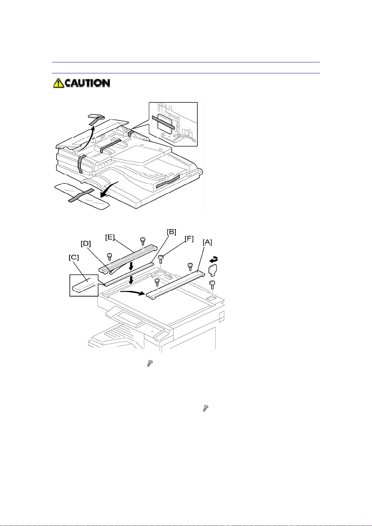
Installation Procedure
Unplug the copier power cord before starting the following procedure.
1. Remove the strips of tape.
2. Remove the left scale [A] (
3. Place the DF exposure glass [B] on the glass holder. Make sure that the white
mark [C] is on the bottom at the front end.
4. Peel off the backing [D] of the double-sided tape attached to the rear side of the
scale guide [E], then install the scale guide (
5. Install the two stud screws [F].
6. Mount the ARDF on the copier, and then slide it to the front.
13
x 2).
x 2 [removed in step 2]).
B245/B276/B277/B268/B269 Service Manual 18-Jan-06
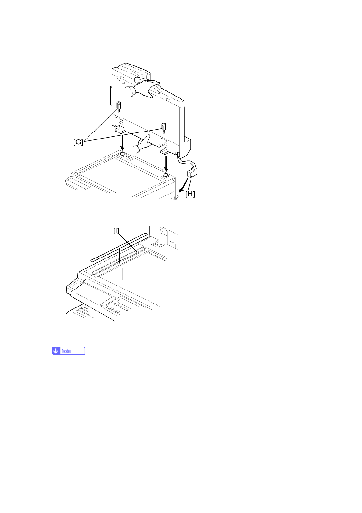
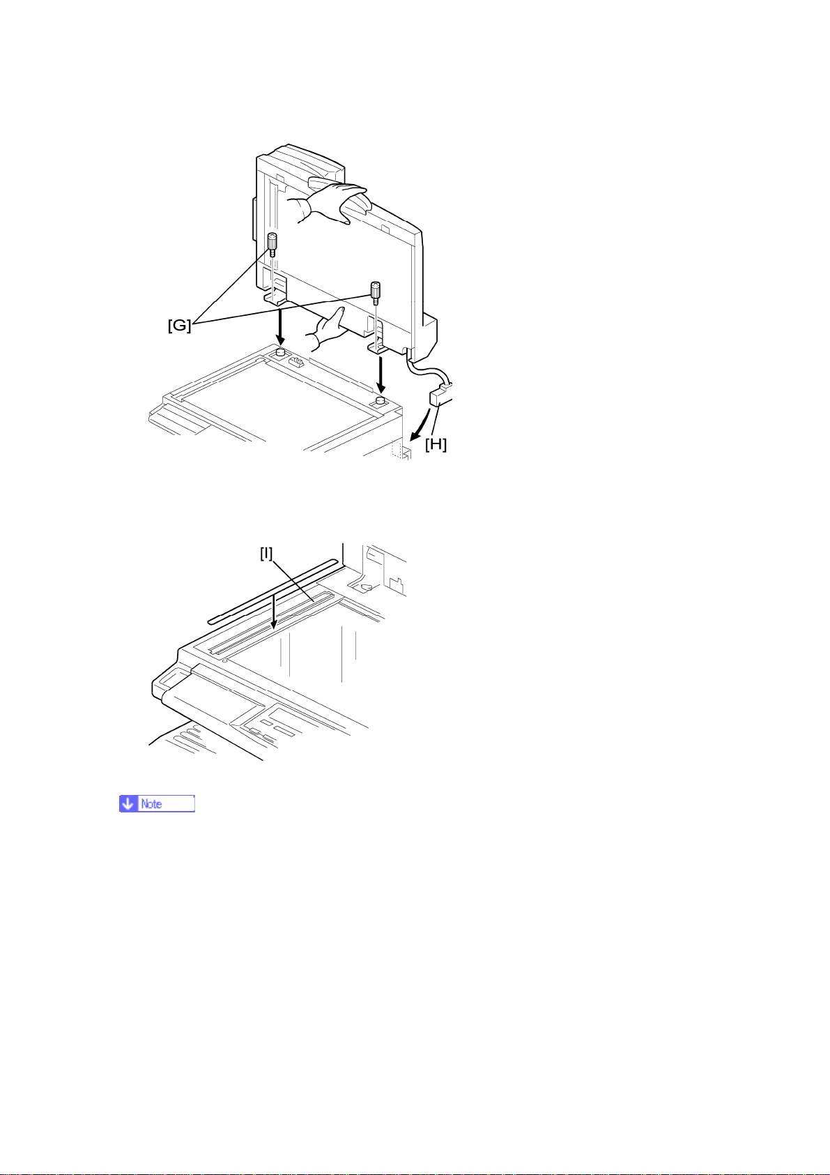
7. Secure the ARDF unit with the knob screws [G].
8. Connect the cable [H] to the copier.
9. Attach the appropriate original size decal [I] as shown.
10. Attach an attention decal to the top cover.
The attention decals in the package are written in different languages.
14
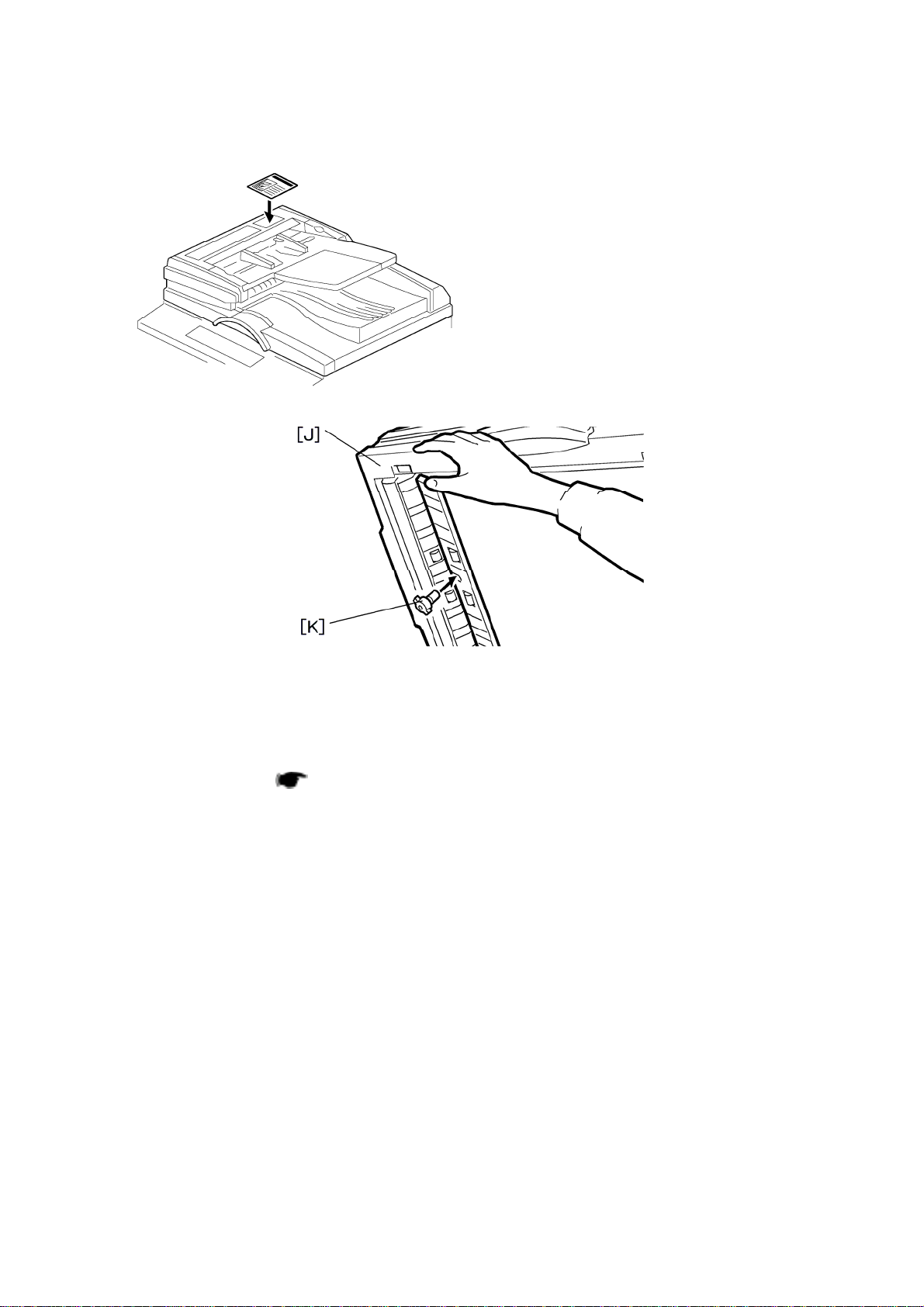
B245/B276/B277/B268/B269 Service Manual 18-Jan-06
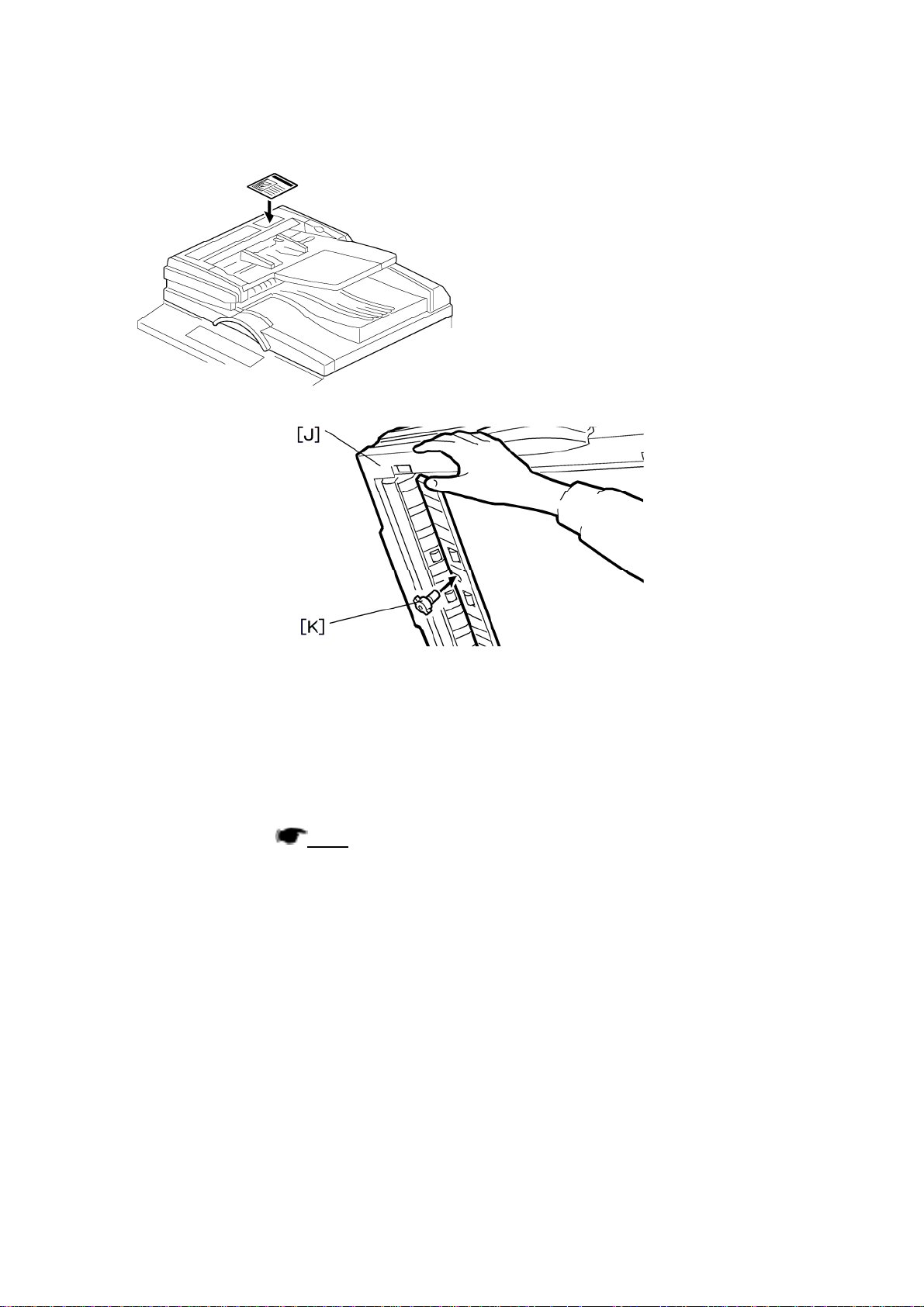
11. Open the ARDF [J].
12. Install the stamp cartridge [K] to the ARDF.
13. Make a full size copy, and check that the side-to-side and leading edge
registrations are correct. If they are not, adjust the side-to-side and leading edge
registrations. (
p.114)
15

B245/B276/B277/B268/B269 Service Manual 18-Jan-06
ADF Installation
Accessory Check
Check the quantity and condition of the accessories against the following list.
No. Description Q’ty
1 Scale Guide 1
2 DF Exposure Glass 1
3 Stud Screw 2
4 Fixing Screw 2
5 Original Size Decal 2
6 Screwdriver Tool 1
7 Attention Decal—Top Cover 1
8 Stamp Cartridge 1
9 Installation Procedure 1
16
B245/B276/B277/B268/B269 Service Manual 18-Jan-06
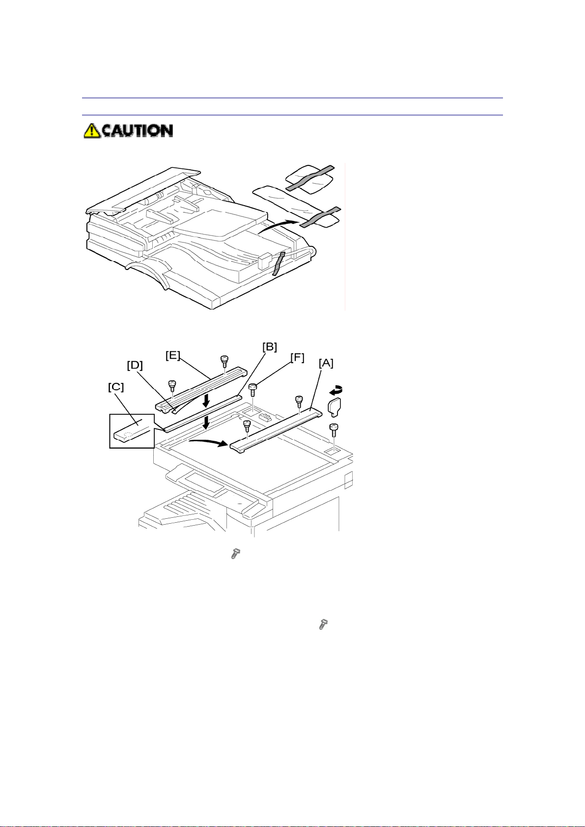
Installation Procedure
Unplug the machine power cord before starting the following procedure.
1. Remove the strips of tape.
2. Remove the left scale [A] (
3. Place the DF exposure glass [B] on the glass holder. Make sure that the white
mark [C] is on the bottom at the front end.
4. Peel off the backing [D] of the double-sided tape attached to the rear side of the
scale guide [E], then install the scale guide (
5. Install the two stud screws [F].
6. Mount the ADF on the copier, and then slide it to the front.
17
x 2).
x 2 [removed in step 2]).
B245/B276/B277/B268/B269 Service Manual 18-Jan-06
7. Secure the ADF unit with the fixing screws [G].
8. Connect the cable [H] to the copier.
9. Attach the appropriate scale decal [I] as shown.
10. Attach an attention decal to the top cover.
The attention decals in the package are written in different languages.
18
B245/B276/B277/B268/B269 Service Manual 18-Jan-06
11. Open the ADF [J].
12. Install the stamp cartridge [K] to the ADF
13. Turn the main power switch on. Then check if the document feeder works
properly.
14. Make a full size copy, and check that the side-to-side and leading edge
registrations are correct. If they are not, adjust the side-to-side and leading edge
registrations. (
p.114).
19
B245/B276/B277/B268/B269 Service Manual 18-Jan-06
Two-tray Paper Tray Unit Installation
Accessory Check
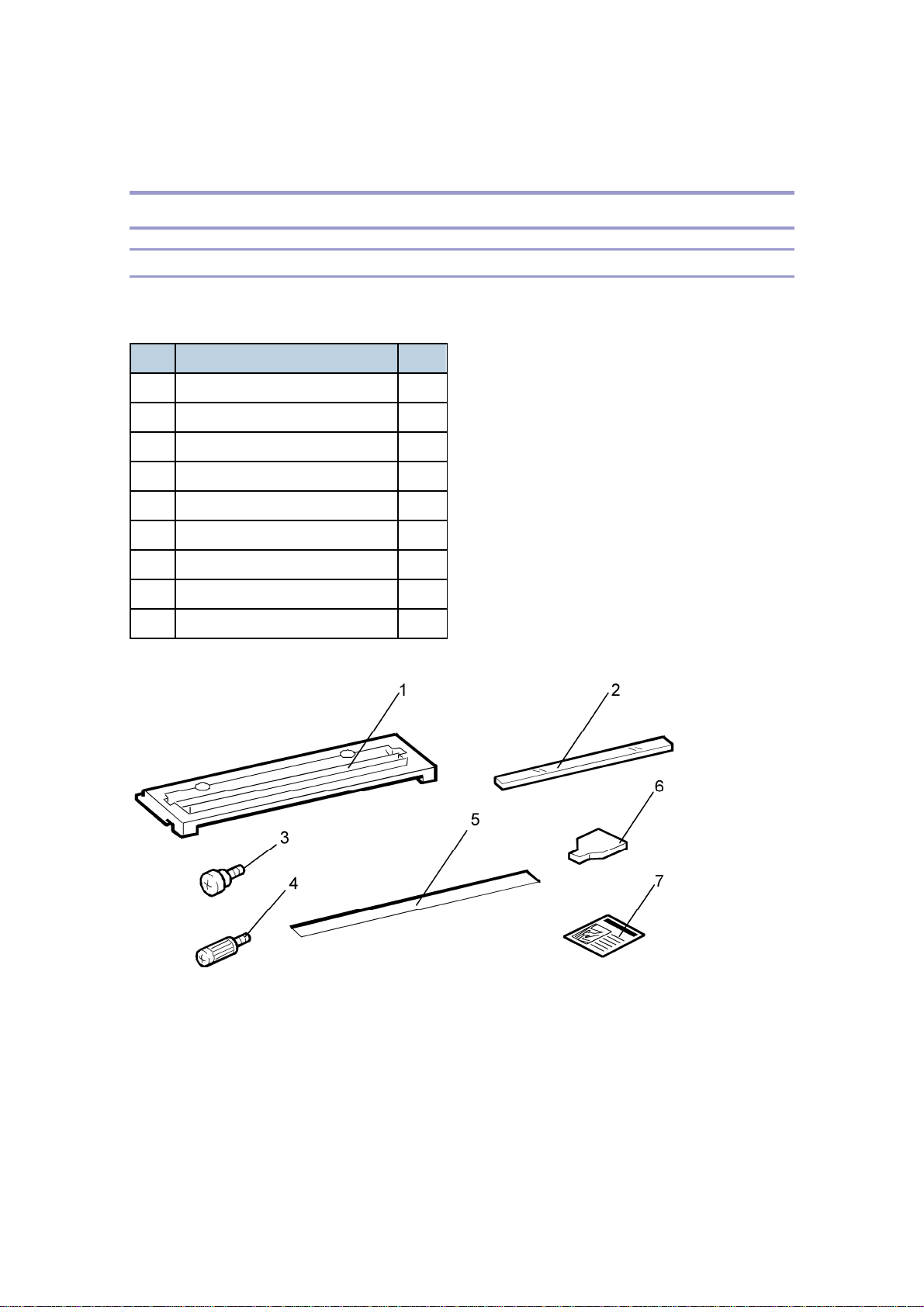
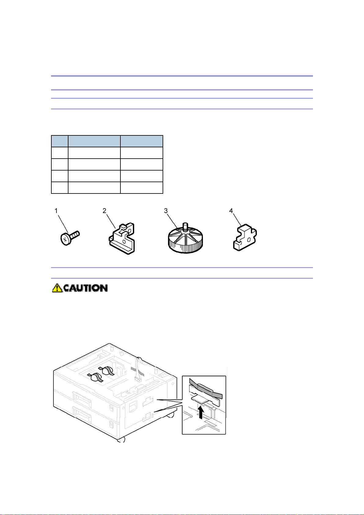
Check the quantity and condition of the accessories against the following list.
No. Description Q’ty
1 Screw – M4x10 10
2 Unit Holder 2 x 2 pieces
3 Adjuster 1
4 Unit Holder 2
Installation Procedure
If the optional printer unit is installed:
Print out all data in the printer buffer.
Disconnect the network cable.
Unplug the machine power cord before starting the following procedure.
1. Remove the strips of tape. Make sure that you have removed all the strips of tape
20
B245/B276/B277/B268/B269 Service Manual 18-Jan-06
and all the pieces of cardboard.
After removing the tape that secures the peripheral components and cardboard
to the paper tray, make sure that there is no tape and/or tape reside remaining
on the tray.
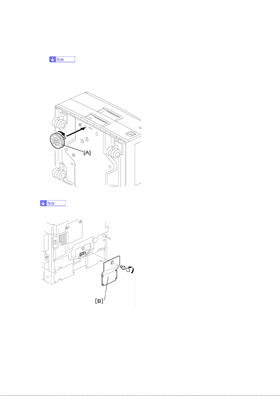
2. Attach the adjuster [A] to the base plate as shown.
This step is not necessary if a cabinet is installed.
3. Remove the cover [B] (1 rivet).
21
 Loading...