

Page 1

A133/A217
SERVICE MANUAL
RICOH GROUP COMPANIES
PN: RCFM0400
Page 2

Page 3

®
®
SERVICE MANUAL
A133/A217
RICOH GROUP COMPANIES
Page 4

Page 5

A133
A217
FIELD SERVICE
MANUAL
PN: RCFM0400
Page 6

Page 7

It is the reader's responsibility when discussing the information contained within this
document to maintain a level of confidentiality that is in the best interest of Ricoh
Corporation and its member companies.
NO PART OF THIS DOCUMENT MAY BE REPRODUCED IN ANY
FASHION AND DISTRIBUTED WITHOUT THE PRIOR
PERMISSION OF RICOH CORPORATION.
All product names, domain names or product illustrations, including desktop images,
used in this document are trademarks, registered trademarks or the property of their
respective companies.
They are used throughout this book in an informational or editorial fashion only and for
the benefit of such companies. No such use, or the use of any trade name, or web
site is intended to convey endorsement or other affiliation with Ricoh products.
2000 RICOH Corporation. All rights reserved.
Page 8

Page 9

LEGEND
PRODUCT CODE COMPANY
RICOH SAVIN GESTETNER
A133 Aficio 400 9940DP 2640E
A217 Aficio 500 9950DP 2850E
DOCUMENTATION HISTORY
REV. NO. DATE COMMENTS
* 6/96 Original Printing
1 11/97 A217 Addition
2 7/98 A612 Addition
Page 10

Page 11

IMPORTANT SAFETY NOTICES
PREVENTION OF PHYSICAL INJURY
1. Before disassembling or assembling parts of the copier and peripherals,
make sure that the cop ier po w er cor d is un plu gg ed .
2. The wall outlet should be ne ar th e cop i er an d ea sil y accessi b le.
3. Note that some compone nt s of th e cop i er an d th e pa pe r tr ay un i t are
supplied with electrical voltage even if the main switch is turned off.
4. If any adjustment or operation check has to be made with exterior covers
off or open while the main switch is turned on, keep hands away from
electrified or mech anically driven comp on en ts.
5. If the start key is pressed before the copier completes the warm-up
period (Start key starts blinking red and green alternatively), keep hands
away from the mechanical and the electrical components as the copier
starts making copies as soon as the warm-up period is completed.
6. The inside and the metal parts of the fusing uni t be com e extr e m ely ho t
while the copier is operating. Be careful to avoid touching those
components with your bare hands.
HEALTH SAFETY CONDITIONS
1. Never operate the copier without the ozone filters installed.
2. Always replace the ozone filters with the specifie d ones at the specified
intervals.
3. Toner and developer are non-toxic, but if you get either of them in your
eyes by accident, it may cause temporary eye discomfort. Try to remove
with eye drops or flush wit h w at er as fir st aid. If unsuccessful, get
medical attention.
OBSERVANCE OF ELECTRICAL SAFETY STANDARDS
1. The copier and its peripherals must be installed and maintained by a
customer service representative who has completed the training course
on those models.
CAUTION
+
2. The RAM board on the system control board has a lithium battery
which can explode if replaced incorrectly. Replace the battery
only with an identical one. The manufacturer recommends
replacing the entire RAM board. Do not recharge or burn this
battery. Used batteries must be handled in accord ance with local
regulations.
FSM a A133/A217
Page 12
SAFETY AND ECOLOGICAL NOTES FOR DISPOSAL
1. Do not incinerate the toner bottle or the used toner. Toner dust may
ignite suddenly when exposed to open flame.
2. Dispose of used toner, de vel o pe r , an d or g an i c pho to con ductor according
to local regulations. (These are non-to xic supp lies. )
3. Dispose of replaced parts in accordance with local regulations.
4. When keeping used lith ium batteries in order to dispose of them later, do
not put more than 100 batteries per sealed bo x. St or i n g lar g er nu m be rs
or not sealing them ap ar t ma y lead to che m i cal rea c tions and heat
build-up.
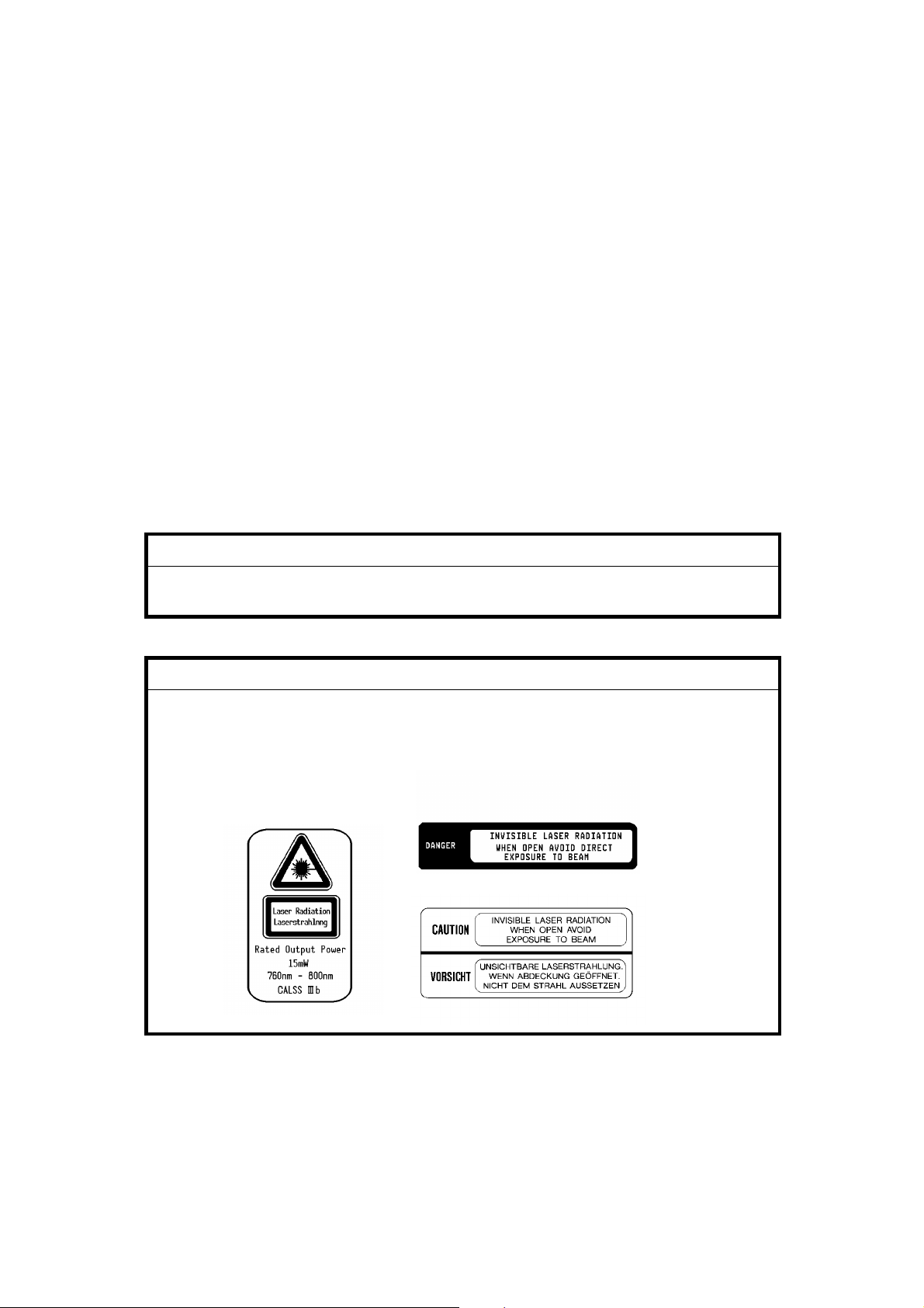
LASER SAFETY
The Center for Devices and Radiological Health (CDRH) prohibits the repair
of laser-based optical units in the field . The optical housing unit can only be
repaired in a factory or at a location with the requisite equipment. The laser
subsystem is replaceable in the field by a qualified Customer Engineer. The
laser chassis is not repairable in the field. Customer engineers are therefore
directed to return all chassis and laser subsystems to the factory or service
depot when replacement of the optical subsystem is required.
WARNING
+
Use of controls, or adju stm e nt, or performanc e of pr oce du res other than
those specified in th is manual may result in hazardous radiation exposure.
WARNING FOR LASER UNIT
+
WARNING: Turn off the main switch before attempting any of the
procedures in the Laser Unit section. Laser beams
can seriously damage your eyes.
CAUTION MARKING:
For 115V version
For 230V version
A133/A217 b FSM
Page 13

Table of Contents
OVERALL MACHINE INFORMATION
1. SPECIFICATIONS . . . . . . . . . . . . . . . . . . . . . . . . . . . . . . . . . . . . . . 1-1
COMPONENT LAYOUT AND DESCRIPTIONS
1. MACHINE CONFIGURATION . . . . . . . . . . . . . . . . . . . . . . . . . . . . 2-1
2. PAPER PATH . . . . . . . . . . . . . . . . . . . . . . . . . . . . . . . . . . . . . . . . 2-2
2.1 NORMAL COPYING . . . . . . . . . . . . . . . . . . . . . . . . . . . . . . . . . . . . . . . . . . . . . 2-2
2.2 DUPLEX COPYING . . . . . . . . . . . . . . . . . . . . . . . . . . . . . . . . . . . . . . . . . . . . . 2-2
3. MECHANICAL COMPONENT LAYOUT . . . . . . . . . . . . . . . . . . . . 2-3
4. ELECTRICAL COMPONENT DESCRIPTIONS . . . . . . . . . . . . . . . 2-5
5. DRIVE LAYOUT . . . . . . . . . . . . . . . . . . . . . . . . . . . . . . . . . . . . . . 2-10
INSTALLATION PROCEDURE
1. INSTALLATION REQUIREMENTS . . . . . . . . . . . . . . . . . . . . . . . . 3-1
1.1 ENVIRONMENT . . . . . . . . . . . . . . . . . . . . . . . . . . . . . . . . . . . . . . . . . . . . . . . . 3-1
1.2 MACHINE LEVEL . . . . . . . . . . . . . . . . . . . . . . . . . . . . . . . . . . . . . . . . . . . . . . . 3-1
1.3 MINIMUM SPACE REQUIREMENTS. . . . . . . . . . . . . . . . . . . . . . . . . . . . . . . . 3-2
1.4 POWER REQUIRMENTS . . . . . . . . . . . . . . . . . . . . . . . . . . . . . . . . . . . . . . . . . 3-2
2. COPIER INSTALLATION . . . . . . . . . . . . . . . . . . . . . . . . . . . . . . . . 3-3
2.1 ACCESSORY CHECK . . . . . . . . . . . . . . . . . . . . . . . . . . . . . . . . . . . . . . . . . . . 3-3
2.2 KEY COUNTER (OPTION) . . . . . . . . . . . . . . . . . . . . . . . . . . . . . . . . . . . . . . 3-11
2.3 TRAY HEATER (OPTION) . . . . . . . . . . . . . . . . . . . . . . . . . . . . . . . . . . . . . . 3-12
2.4 DRUM HEATER (OPTION) . . . . . . . . . . . . . . . . . . . . . . . . . . . . . . . . . . . . . . 3-13
2.5 OPTICS ANTI-CONDENSATION HEATER (OPTION) . . . . . . . . . . . . . . . . . 3-14
3. PAPER SIZE SELECTION . . . . . . . . . . . . . . . . . . . . . . . . . . . . . . 3-15
3.1 OPTIONAL PAPER FEED UNIT. . . . . . . . . . . . . . . . . . . . . . . . . . . . . . . . . . . 3-15
3.2 1ST TRAY - NON-STANDARD PAPER SIZE SELECTION . . . . . . . . . . . . . 3-16
3.3 1ST TRAY - F/F4 SIZE PAPER SELECTION . . . . . . . . . . . . . . . . . . . . . . . . 3-17
FSM i A133/A217
Page 14

SERVICE TABLES
1. SERVICE REMARKS . . . . . . . . . . . . . . . . . . . . . . . . . . . . . . . . . . . 4-1
1.1 GENERAL CAUTION . . . . . . . . . . . . . . . . . . . . . . . . . . . . . . . . . . . . . . . . . . . . 4-1
1.2 DRUM . . . . . . . . . . . . . . . . . . . . . . . . . . . . . . . . . . . . . . . . . . . . . . . . . . . . . . . . 4-1
1.3 TRANSFER BELT UNIT . . . . . . . . . . . . . . . . . . . . . . . . . . . . . . . . . . . . . . . . . . 4-2
1.4 SCANNER UNIT . . . . . . . . . . . . . . . . . . . . . . . . . . . . . . . . . . . . . . . . . . . . . . . . 4-2
1.5 LASER UNIT . . . . . . . . . . . . . . . . . . . . . . . . . . . . . . . . . . . . . . . . . . . . . . . . . . . 4-3
1.6 CHARGE CORONA UNIT. . . . . . . . . . . . . . . . . . . . . . . . . . . . . . . . . . . . . . . . . 4-3
1.7 DEVELOPMENT . . . . . . . . . . . . . . . . . . . . . . . . . . . . . . . . . . . . . . . . . . . . . . . . 4-3
1.8 DRUM CLEANING . . . . . . . . . . . . . . . . . . . . . . . . . . . . . . . . . . . . . . . . . . . . . . 4-4
1.9 FUSING UNIT . . . . . . . . . . . . . . . . . . . . . . . . . . . . . . . . . . . . . . . . . . . . . . . . . . 4-4
1.10 PAPER FEED . . . . . . . . . . . . . . . . . . . . . . . . . . . . . . . . . . . . . . . . . . . . . . . . . 4-5
1.11 USED TONER. . . . . . . . . . . . . . . . . . . . . . . . . . . . . . . . . . . . . . . . . . . . . . . . . 4-5
1.12 OTHERS . . . . . . . . . . . . . . . . . . . . . . . . . . . . . . . . . . . . . . . . . . . . . . . . . . . . . 4-5
2. SERVICE PROGRAM MODE . . . . . . . . . . . . . . . . . . . . . . . . . . . . . 4-6
2.1 SERVICE PROGRAM MODE OPERATION . . . . . . . . . . . . . . . . . . . . . . . . . . 4-6
2.1.1 Service Program Access Procedure . . . . . . . . . . . . . . . . . . . . . . . . . . . . . 4-6
2.1.2 Accessing Copy Mode from within an SP Mode . . . . . . . . . . . . . . . . . . . 4-7
2.1.3 To Input a Value or Setting for an SP Mode . . . . . . . . . . . . . . . . . . . . . . . 4-7
2.2 SERVICE PROGRAM MODE TABLES . . . . . . . . . . . . . . . . . . . . . . . . . . . . . . 4-8
2.2.1 MAIN SP MODE TABLE . . . . . . . . . . . . . . . . . . . . . . . . . . . . . . . . . . . . . . 4-8
2.2.2 TEST PATTERN PRINTING (SP 2902) . . . . . . . . . . . . . . . . . . . . . . . . . 4-26
2.2.3 INPUT CHECK (SP5803) . . . . . . . . . . . . . . . . . . . . . . . . . . . . . . . . . . . 4-27
2.2.4 OUTPUT CHECK (SP5804) . . . . . . . . . . . . . . . . . . . . . . . . . . . . . . . . . . 4-31
2.2.5 SYSTEM PARAMETER AND DATA LISTS (SP5990) . . . . . . . . . . . . . . 4-33
2.3 SP MODE AFTER REPLACEMENT AND CLEANING. . . . . . . . . . . . . . . . . . 4-34
2.4 MEMORY ALL CLEAR (SP5801) . . . . . . . . . . . . . . . . . . . . . . . . . . . . . . . . . . 4-35
2.5 USER CODE FEATURE . . . . . . . . . . . . . . . . . . . . . . . . . . . . . . . . . . . . . . . . . 4-35
3. USER PROGRAM MODE . . . . . . . . . . . . . . . . . . . . . . . . . . . . . . 4-36
3.1 How to Enter and Leave UP Mode . . . . . . . . . . . . . . . . . . . . . . . . . . . . . . . . . 4-36
3.2
UP Mode Table
. . . . . . . . . . . . . . . . . . . . . . . . . . . . . . . . . . . . . . . . . . . . . . . . 4-36
4. TEST POINTS/DIP SWITCHES/LEDS . . . . . . . . . . . . . . . . . . . . . 4-38
4.1 DIP SWITCHES . . . . . . . . . . . . . . . . . . . . . . . . . . . . . . . . . . . . . . . . . . . . . . . 4-38
4.2 TEST POINTS. . . . . . . . . . . . . . . . . . . . . . . . . . . . . . . . . . . . . . . . . . . . . . . . . 4-38
A133/A217 ii FSM
Page 15

4.3 LEDS. . . . . . . . . . . . . . . . . . . . . . . . . . . . . . . . . . . . . . . . . . . . . . . . . . . . . . . . 4-39
4.4 VARIABLE RESISTORS. . . . . . . . . . . . . . . . . . . . . . . . . . . . . . . . . . . . . . . . . 4-39
5. PREVENTIVE MAINTENANCE SCHEDULE . . . . . . . . . . . . . . . . 4-40
5.1 PM TABLE. . . . . . . . . . . . . . . . . . . . . . . . . . . . . . . . . . . . . . . . . . . . . . . . . . . . 4-40
5.2 REGULAR PM PROCEDURE. . . . . . . . . . . . . . . . . . . . . . . . . . . . . . . . . . . . . 4-43
6. SPECIAL TOOLS AND LUBRICANTS. . . . . . . . . . . . . . . . . . . . . 4-47
6.1 SPECIAL TOOLS AND LUBRICANTS . . . . . . . . . . . . . . . . . . . . . . . . . . . . . . 4-47
6.2 SPECIAL PARTS . . . . . . . . . . . . . . . . . . . . . . . . . . . . . . . . . . . . . . . . . . . . . . 4-47
REPLACEMENT AND ADJUSTMENT
1. INNER AND OUTER COVERS . . . . . . . . . . . . . . . . . . . . . . . . . . . 5-1
1.1 OUTER COVER REMOVAL . . . . . . . . . . . . . . . . . . . . . . . . . . . . . . . . . . . . . . . 5-1
1.1.1 Front Cover . . . . . . . . . . . . . . . . . . . . . . . . . . . . . . . . . . . . . . . . . . . . . . . . 5-1
1.1.2 Rear Cover . . . . . . . . . . . . . . . . . . . . . . . . . . . . . . . . . . . . . . . . . . . . . . . . 5-1
1.1.3 Left Cover . . . . . . . . . . . . . . . . . . . . . . . . . . . . . . . . . . . . . . . . . . . . . . . . . 5-1
1.1.4 Top Cover . . . . . . . . . . . . . . . . . . . . . . . . . . . . . . . . . . . . . . . . . . . . . . . . . 5-1
1.1.5 Operation Panel . . . . . . . . . . . . . . . . . . . . . . . . . . . . . . . . . . . . . . . . . . . . 5-2
1.1.6 Right Upper Cover. . . . . . . . . . . . . . . . . . . . . . . . . . . . . . . . . . . . . . . . . . . 5-2
1.1.7 Front Upper Cover. . . . . . . . . . . . . . . . . . . . . . . . . . . . . . . . . . . . . . . . . . . 5-2
1.1.8 Right Cover . . . . . . . . . . . . . . . . . . . . . . . . . . . . . . . . . . . . . . . . . . . . . . . . 5-3
1.2 INNER COVER REMOVAL . . . . . . . . . . . . . . . . . . . . . . . . . . . . . . . . . . . . . . . 5-4
1.2.1 Right Inner Cover. . . . . . . . . . . . . . . . . . . . . . . . . . . . . . . . . . . . . . . . . . . . 5-4
1.2.2 Middle Inner Cover . . . . . . . . . . . . . . . . . . . . . . . . . . . . . . . . . . . . . . . . . . 5-4
1.2.3 Left Inner Cover. . . . . . . . . . . . . . . . . . . . . . . . . . . . . . . . . . . . . . . . . . . . . 5-4
2. SCANNER . . . . . . . . . . . . . . . . . . . . . . . . . . . . . . . . . . . . . . . . . . . . 5-5
2.1 EXPOSURE GLASS REMOVAL . . . . . . . . . . . . . . . . . . . . . . . . . . . . . . . . . . . 5-5
2.2 EXPOSURE LAMP REPLACEMENT . . . . . . . . . . . . . . . . . . . . . . . . . . . . . . . . 5-6
2.3 SCANNER WIRE REPLACEMENT . . . . . . . . . . . . . . . . . . . . . . . . . . . . . . . . . 5-7
2.3.1 Front Scanner Wire Replacement . . . . . . . . . . . . . . . . . . . . . . . . . . . . . . . 5-7
2.3.2 Rear Scanner Wire Replacement . . . . . . . . . . . . . . . . . . . . . . . . . . . . . 5-10
2.3.3 Scanner Position Adjustment . . . . . . . . . . . . . . . . . . . . . . . . . . . . . . . . . 5-14
2.4 SCANNER HOME POSITION SENSOR REPLACEMENT . . . . . . . . . . . . . . 5-15
2.5 SCANNER DRIVE MOTOR . . . . . . . . . . . . . . . . . . . . . . . . . . . . . . . . . . . . . . 5-15
3. LASER EXPOSURE . . . . . . . . . . . . . . . . . . . . . . . . . . . . . . . . . . . 5-16
FSM iii A133/A217
Page 16

3.1 POLYGON MIRROR MOTOR REPLACEMENT . . . . . . . . . . . . . . . . . . . . . . 5-17
3.2 LD UNIT REPLACEMENT . . . . . . . . . . . . . . . . . . . . . . . . . . . . . . . . . . . . . . 5-18
3.3 MAIN SCAN SYNCHRONIZATION DETECTOR BOARD REPLACEMENT . 5-19
4. DEVELOPMENT AND TONER SUPPLY . . . . . . . . . . . . . . . . . . 5-20
4.1 DEVELOPMENT UNIT REMOVAL . . . . . . . . . . . . . . . . . . . . . . . . . . . . . . . . . 5-20
4.2 DEVELOPER REPLACEMENT . . . . . . . . . . . . . . . . . . . . . . . . . . . . . . . . . . 5-21
4.3 TONER SUPPLY MOTOR REPLACEMENT . . . . . . . . . . . . . . . . . . . . . . . 5-23
4.4 DEVELOPMENT DRIVE CLUTCH AND TONER SUPPLY CLUTCH
REPLACEMENT . . . . . . . . . . . . . . . . . . . . . . . . . . . . . . . . . . . . . . . . . . . . . . . . . 5-24
4.5 TD SENSOR REPLACEMENT . . . . . . . . . . . . . . . . . . . . . . . . . . . . . . . . . . . . 5-25
5. AROUND THE DRUM. . . . . . . . . . . . . . . . . . . . . . . . . . . . . . . . . . 5-26
5.1 DRUM UNIT REMOVAL . . . . . . . . . . . . . . . . . . . . . . . . . . . . . . . . . . . . . . . . 5-26
5.2 DRUM REPLACEMENT . . . . . . . . . . . . . . . . . . . . . . . . . . . . . . . . . . . . . . . . . 5-27
5.3 PICK-OFF PAWL REPLACEMENT . . . . . . . . . . . . . . . . . . . . . . . . . . . . . . 5-28
5.4 ID SENSOR BOARD REPLACEMENT . . . . . . . . . . . . . . . . . . . . . . . . . . . . . 5-29
5.5 DRUM CLEANING BLADE REPLACEMENT . . . . . . . . . . . . . . . . . . . . . . . . . 5-30
5.6 CLEANING BRUSH REPLACEMENT . . . . . . . . . . . . . . . . . . . . . . . . . . . . . . 5-30
5.7 CHARGE CORONA GRID PLATE REPLACEMENT . . . . . . . . . . . . . . . . . . . 5-31
5.8 CORONA WIRE REPLACEMENT . . . . . . . . . . . . . . . . . . . . . . . . . . . . . . . . . 5-31
5.9 QUENCHING LAMP REPLACEMENT . . . . . . . . . . . . . . . . . . . . . . . . . . . . . . 5-32
6. TRANSFER BELT UNIT . . . . . . . . . . . . . . . . . . . . . . . . . . . . . . . . 5-33
6.1 TRANSFER BELT UNIT REPLACEMENT . . . . . . . . . . . . . . . . . . . . . . . . . . 5-33
6.2 TRANSFER BELT REMOVAL . . . . . . . . . . . . . . . . . . . . . . . . . . . . . . . . . . . 5-34
6.3 TRANSFER BELT CLEANING BLADE REPLACEMENT . . . . . . . . . . . . . . . 5-35
6.4 TRANSFER BELT LIFT CLUTCH . . . . . . . . . . . . . . . . . . . . . . . . . . . . . . . . . 5-36
7. PAPER FEED . . . . . . . . . . . . . . . . . . . . . . . . . . . . . . . . . . . . . . . . 5-37
7.1 LCT PICK-UP, SEPARATION, AND FEED
ROLLER REPLACEMENT . . . . . . . . . . . . . . . . . . . . . . . . . . . . . . . . . . . . . . 5-37
7.2 TRAY PI CK-UP, SEPARATION, AND FEED
ROLLER REPLACEMENT . . . . . . . . . . . . . . . . . . . . . . . . . . . . . . . . . . . . . . 5-38
7.3 PAPER FEED TRAY REPLACEMENT . . . . . . . . . . . . . . . . . . . . . . . . . . . . . 5-39
7.4 BYPASS PAPER FEED UNIT REMOVAL . . . . . . . . . . . . . . . . . . . . . . . . . . 5-40
7.5 TRAY PAPER FEED UNIT REMOVAL . . . . . . . . . . . . . . . . . . . . . . . . . . . . . 5-41
7.6 REGISTRATION SENSOR REPLACEMENT . . . . . . . . . . . . . . . . . . . . . . . . 5-42
7.7 BY-PASS FEED AND BY-PASS RELAY CLUTCH REPLACEMENT . . . . . . 5-43
7.8 PAPER FEED CLUTCH REPLACEMENT . . . . . . . . . . . . . . . . . . . . . . . . . . . 5-44
A133/A217 iv FSM
Page 17

7.9 RELAY CLUTCH REPLACEMENT. . . . . . . . . . . . . . . . . . . . . . . . . . . . . . . . . 5-44
7.10 REGISTRATION CLUTCH REPLACEMENT . . . . . . . . . . . . . . . . . . . . . . . 5-45
8. LCT UNIT. . . . . . . . . . . . . . . . . . . . . . . . . . . . . . . . . . . . . . . . . . . . 5-46
8.1 LCT UNIT REMOVAL . . . . . . . . . . . . . . . . . . . . . . . . . . . . . . . . . . . . . . . . . . 5-46
8.2 LCT DRIVE BELT REPLACEMENT . . . . . . . . . . . . . . . . . . . . . . . . . . . . . . . 5-47
8.3 LCT MOTOR REPLACEMENT . . . . . . . . . . . . . . . . . . . . . . . . . . . . . . . . . . . 5-48
9. FUSING . . . . . . . . . . . . . . . . . . . . . . . . . . . . . . . . . . . . . . . . . . . . . 5-49
9.1 FUSING UNIT REMOVAL . . . . . . . . . . . . . . . . . . . . . . . . . . . . . . . . . . . . . . . 5-49
9.2 FUSING LAMP REPLACEMENT . . . . . . . . . . . . . . . . . . . . . . . . . . . . . . . . . . 5-50
9.3 HOT ROLLER REPLACEMENT . . . . . . . . . . . . . . . . . . . . . . . . . . . . . . . . . . . 5-51
9.4 PRESSURE ROLLER AND CLEANING ROLLER REPLACEMENT . . . . . . . 5-52
9.5 THERMISTOR REPLACEMENT . . . . . . . . . . . . . . . . . . . . . . . . . . . . . . . . . . 5-53
9.6 THERMOFUSE REPLACEMENT . . . . . . . . . . . . . . . . . . . . . . . . . . . . . . . . . 5-54
9.7 HOT ROLLER STRIPPER PAWL REPLACEMENT . . . . . . . . . . . . . . . . . . . 5-55
10. DUPLEX UNIT. . . . . . . . . . . . . . . . . . . . . . . . . . . . . . . . . . . . . . . 5-56
10.1 DUPLEX UNIT REMOVAL . . . . . . . . . . . . . . . . . . . . . . . . . . . . . . . . . . . . . . 5-56
10.2 FRICTION ROLLER REPLACEMENT . . . . . . . . . . . . . . . . . . . . . . . . . . . . . 5-57
10.3 DUPLEX FEED ROLLER REPLACEMENT . . . . . . . . . . . . . . . . . . . . . . . . . 5-58
10.4 DUPLEX FEED MOTOR REPLACEMENT. . . . . . . . . . . . . . . . . . . . . . . . . . 5-59
11. OTHERS . . . . . . . . . . . . . . . . . . . . . . . . . . . . . . . . . . . . . . . . . . . 5-61
11.1 FILTERS . . . . . . . . . . . . . . . . . . . . . . . . . . . . . . . . . . . . . . . . . . . . . . . . . . . . 5-61
11.1.1 Optics Dust Filter. . . . . . . . . . . . . . . . . . . . . . . . . . . . . . . . . . . . . . . . . . 5-61
11.1.2 Fusing Exhaust Fan Filter . . . . . . . . . . . . . . . . . . . . . . . . . . . . . . . . . . . 5-61
11.1.3 Ozone Filter. . . . . . . . . . . . . . . . . . . . . . . . . . . . . . . . . . . . . . . . . . . . . . 5-61
11.2 PCB REPLACEMENT . . . . . . . . . . . . . . . . . . . . . . . . . . . . . . . . . . . . . . . . . 5-62
11.2.1 SBU Assembly/EX-IPU Replacement . . . . . . . . . . . . . . . . . . . . . . . . . . 5-62
11.2.2 HDD Unit Replacement . . . . . . . . . . . . . . . . . . . . . . . . . . . . . . . . . . . . 5-63
11.2.3 SCU Board Replacement . . . . . . . . . . . . . . . . . . . . . . . . . . . . . . . . . . . 5-64
11.2.4 BCU Board Replacement . . . . . . . . . . . . . . . . . . . . . . . . . . . . . . . . . . . 5-64
11.2.5 AC Drive Board . . . . . . . . . . . . . . . . . . . . . . . . . . . . . . . . . . . . . . . . . . . 5-65
11.2.6 DC Power Supply Unit . . . . . . . . . . . . . . . . . . . . . . . . . . . . . . . . . . . . . 5-66
11.2.7 High Voltage Control Board . . . . . . . . . . . . . . . . . . . . . . . . . . . . . . . . . 5-67
11.2.8 Lamp Stabilizer . . . . . . . . . . . . . . . . . . . . . . . . . . . . . . . . . . . . . . . . . . . 5-68
11.2.9 Scanner Drive Board . . . . . . . . . . . . . . . . . . . . . . . . . . . . . . . . . . . . . . . 5-69
FSM v A133/A217
Page 18

Rev.10/97
11.2.10 Charge High Voltage Supply Board. . . . . . . . . . . . . . . . . . . . . . . . . . . 5-69
11.2.11 Main Motor. . . . . . . . . . . . . . . . . . . . . . . . . . . . . . . . . . . . . . . . . . . . . . 5-69
11.2.12 Development Bias Power Pack . . . . . . . . . . . . . . . . . . . . . . . . . . . . . 5-70
11.2.13 Transfer High Voltage Supply Board . . . . . . . . . . . . . . . . . . . . . . . . . 5-71
12. COPY IMAGE ADJUSTMENT- PRINTING/SCANNING . . . . . . 5-72
12.1 Printing . . . . . . . . . . . . . . . . . . . . . . . . . . . . . . . . . . . . . . . . . . . . . . . . . . . . . 5-72
12.1.1 Registration - Leading Edge/Side-to-Side . . . . . . . . . . . . . . . . . . . . . . 5-72
12.1.2 Blank Margins . . . . . . . . . . . . . . . . . . . . . . . . . . . . . . . . . . . . . . . . . . . . 5-73
12.1.3 Double Copy Side-to-side Registration . . . . . . . . . . . . . . . . . . . . . . . . . 5-73
12.2 Scanning . . . . . . . . . . . . . . . . . . . . . . . . . . . . . . . . . . . . . . . . . . . . . . . . . . . . 5-74
12.2.1 Registration: Platen Mode . . . . . . . . . . . . . . . . . . . . . . . . . . . . . . . . . . 5-74
12.2.2 Registration: ADF . . . . . . . . . . . . . . . . . . . . . . . . . . . . . . . . . . . . . . . . 5-75
12.3 Magnification . . . . . . . . . . . . . . . . . . . . . . . . . . . . . . . . . . . . . . . . . . . . . . . . 5-76
12.3.1 Main Scan Magnification . . . . . . . . . . . . . . . . . . . . . . . . . . . . . . . . . . . . 5-76
12.3.2 Sub Scan Magnification . . . . . . . . . . . . . . . . . . . . . . . . . . . . . . . . . . . . 5-76
13. TOUCH SCREEN ADJUSTMENT . . . . . . . . . . . . . . . . . . . . . . . 5-77
TROUBLESHOOTING
1. SERVICE CALL CONDITIONS. . . . . . . . . . . . . . . . . . . . . . . . . . . . 6-1
1.1 SUMMARY . . . . . . . . . . . . . . . . . . . . . . . . . . . . . . . . . . . . . . . . . . . . . . . . . . . . 6-1
2. SC CODE DESCRIPTIONS. . . . . . . . . . . . . . . . . . . . . . . . . . . . . . . 6-3
3. ELECTRICAL COMPONENT DEFECTS . . . . . . . . . . . . . . . . . . . 6-17
3.1 SENSORS. . . . . . . . . . . . . . . . . . . . . . . . . . . . . . . . . . . . . . . . . . . . . . . . . . . . 6-17
3.2 SWITCHES . . . . . . . . . . . . . . . . . . . . . . . . . . . . . . . . . . . . . . . . . . . . . . . . . . . 6-19
4. BLOWN FUSE CONDITIONS. . . . . . . . . . . . . . . . . . . . . . . . . . . . 6-20
5. BCU Board History. . . . . . . . . . . . . . . . . . . . . . . . . . . . . . . . . . . . 6-20
AUTO REVERSE DOCUMENT FEEDER (A548)
1. SPECIFICATIONS. . . . . . . . . . . . . . . . . . . . . . . . . . . . . . . . . . . . . . 7-1
2. COMPONENT LAYOUT . . . . . . . . . . . . . . . . . . . . . . . . . . . . . . . . . 7-2
2.1 MECHANICAL COMPONENTS . . . . . . . . . . . . . . . . . . . . . . . . . . . . . . . . . . . . 7-2
2.2 ELECTRICAL COMPONENTS . . . . . . . . . . . . . . . . . . . . . . . . . . . . . . . . . . . . . 7-3
A133/A217 vi FSM
Page 19

3. ELECTRICAL COMPONENT DESCRIPTION . . . . . . . . . . . . . . . . 7-4
4. INSTALLATION. . . . . . . . . . . . . . . . . . . . . . . . . . . . . . . . . . . . . . . . 7-5
4.1 ACCESSORY CHECK . . . . . . . . . . . . . . . . . . . . . . . . . . . . . . . . . . . . . . . . . . . 7-5
4.2 INSTALLATION PROCEDURE. . . . . . . . . . . . . . . . . . . . . . . . . . . . . . . . . . . . . 7-6
5. SERVICE TABLES . . . . . . . . . . . . . . . . . . . . . . . . . . . . . . . . . . . . . 7-7
5.1 DIP SWITCHES . . . . . . . . . . . . . . . . . . . . . . . . . . . . . . . . . . . . . . . . . . . . . . . . 7-7
5.2 VARIABLE RESISTORS. . . . . . . . . . . . . . . . . . . . . . . . . . . . . . . . . . . . . . . . . . 7-8
5.3 LED . . . . . . . . . . . . . . . . . . . . . . . . . . . . . . . . . . . . . . . . . . . . . . . . . . . . . . . . . . 7-8
5.4 FUSE. . . . . . . . . . . . . . . . . . . . . . . . . . . . . . . . . . . . . . . . . . . . . . . . . . . . . . . . . 7-8
6. REPLACEMENT AND ADJUSTMENT. . . . . . . . . . . . . . . . . . . . . . 7-9
6.1 TRANSPORT BELT REPLACEMENT . . . . . . . . . . . . . . . . . . . . . . . . . . . . . . . 7-9
6.2 FEED ROLLER REPLACEMENT . . . . . . . . . . . . . . . . . . . . . . . . . . . . . . . . . . 7-10
6.3 FRICTION BELT REPLACEMENT . . . . . . . . . . . . . . . . . . . . . . . . . . . . . . . . . 7-11
6.4 ORIGINAL SET AND ORIGINAL WIDTH SENSOR REPLACEMENT . . . . . . 7-12
6.5 VERTICAL REGISTRATION ADJUSTMENT . . . . . . . . . . . . . . . . . . . . . . . . . 7-13
6.5.1 One-sided Thin Original Mode. . . . . . . . . . . . . . . . . . . . . . . . . . . . . . . . . 7-13
6.5.2 Two-sided Original Mode. . . . . . . . . . . . . . . . . . . . . . . . . . . . . . . . . . . . . 7-13
6.6 SIDE-TO-SIDE REGISTRATION (DF POSITIONING) ADJUSTMENT . . . . . 7-15
PAPER TRAY UNIT (A549/A550)
1. SPECIFICATIONS. . . . . . . . . . . . . . . . . . . . . . . . . . . . . . . . . . . . . . 8-1
2. COMPONENT LAYOUT . . . . . . . . . . . . . . . . . . . . . . . . . . . . . . . . . 8-2
2.1 MECHANICAL COMPONENT LAYOUT. . . . . . . . . . . . . . . . . . . . . . . . . . . . . . 8-2
2.2 DRIVE LAYOUT . . . . . . . . . . . . . . . . . . . . . . . . . . . . . . . . . . . . . . . . . . . . . . . . 8-3
2.3 ELECTRICAL COMPONENT DESCRIPTION . . . . . . . . . . . . . . . . . . . . . . . . . 8-4
3. INSTALLATION. . . . . . . . . . . . . . . . . . . . . . . . . . . . . . . . . . . . . . . . 8-6
3.1 ACCESSORY CHECK . . . . . . . . . . . . . . . . . . . . . . . . . . . . . . . . . . . . . . . . . . . 8-6
3.2 INSTALLATION PROCEDURE . . . . . . . . . . . . . . . . . . . . . . . . . . . . . . . . . . . 8-7
3.3 TRAY HEATER (OPTION) . . . . . . . . . . . . . . . . . . . . . . . . . . . . . . . . . . . . . . . . 8-9
4. SERVICE TABLES . . . . . . . . . . . . . . . . . . . . . . . . . . . . . . . . . . . . 8-10
4.1 DIP SWITCHES . . . . . . . . . . . . . . . . . . . . . . . . . . . . . . . . . . . . . . . . . . . . . . . 8-10
4.2 TEST POINTS. . . . . . . . . . . . . . . . . . . . . . . . . . . . . . . . . . . . . . . . . . . . . . . . . 8-11
5. REPLACEMENT AND ADJUSTMENT. . . . . . . . . . . . . . . . . . . . . 8-12
FSM vii A133/A217
Page 20

Rev. 10/97
5.1 EXTERIOR COVER REMOVAL . . . . . . . . . . . . . . . . . . . . . . . . . . . . . . . . . . . 8-12
5.2 PAPER FEED CLUTCH REPLACEMENT . . . . . . . . . . . . . . . . . . . . . . . . . . . 8-13
5.3 PAPER FEED UNIT REPLACEMENT . . . . . . . . . . . . . . . . . . . . . . . . . . . . . . 8-14
5.4 FEED ROLLER, PICK-UP ROLLER, AND REVERSE
ROLLER REPLACEMENT . . . . . . . . . . . . . . . . . . . . . . . . . . . . . . . . . . . . . . . 8-15
5.5 RELAY SENSOR REPLACEMENT . . . . . . . . . . . . . . . . . . . . . . . . . . . . . . . . 8-16
FINISHER (A612)
1. OVERALL MACHINE INFORMATION . . . . . . . . . . . . . . . . . . . . . . 9-1
1.1 SPECIFICATIONS . . . . . . . . . . . . . . . . . . . . . . . . . . . . . . . . . . . . . . . . . . . . . . 9-1
1.2 MECHANICAL COMPONENT LAYOUT . . . . . . . . . . . . . . . . . . . . . . . . . . . . . 9-3
1.3 ELECTRICAL COMPONENT DESCRIPTION . . . . . . . . . . . . . . . . . . . . . . . . . 9-4
1.4 DRIVE LAYOUT . . . . . . . . . . . . . . . . . . . . . . . . . . . . . . . . . . . . . . . . . . . . . . 9-6
2. INSTALLATION PROCEDURE . . . . . . . . . . . . . . . . . . . . . . . . . . . 9-7
3. SERVICE TABLES . . . . . . . . . . . . . . . . . . . . . . . . . . . . . . . . . . . . 9-12
3.1 TEST POINT TABLE (MAIN BOARD). . . . . . . . . . . . . . . . . . . . . . . . . . . . . . . 9-12
3.2 FUSE TABLE . . . . . . . . . . . . . . . . . . . . . . . . . . . . . . . . . . . . . . . . . . . . . . . . . 9-12
3.3 LED TABLE. . . . . . . . . . . . . . . . . . . . . . . . . . . . . . . . . . . . . . . . . . . . . . . . . . . 9-12
3.4 DIP SW TABLE . . . . . . . . . . . . . . . . . . . . . . . . . . . . . . . . . . . . . . . . . . . . . . . . 9-12
3.4.1 Factory Setting. . . . . . . . . . . . . . . . . . . . . . . . . . . . . . . . . . . . . . . . . . . . . 9-12
3.4.2 Motor Test Mode . . . . . . . . . . . . . . . . . . . . . . . . . . . . . . . . . . . . . . . . . . . 9-12
3.4.3 Free Run Test Mode Without Paper . . . . . . . . . . . . . . . . . . . . . . . . . . . . 9-13
4. REPLACEMENT AND ADJUSTMENT . . . . . . . . . . . . . . . . . . . . 9-14
4.1 EXTERIOR REMOVAL . . . . . . . . . . . . . . . . . . . . . . . . . . . . . . . . . . . . . . . . . 9-14
4.2 ALIGNMENT BRUSH ROLLER REPLACEMENT . . . . . . . . . . . . . . . . . . . . 9-15
4.3 STACK HEIGHT SENSOR REPLACEMENT . . . . . . . . . . . . . . . . . . . . . . . . 9-16
4.4 POSITIONING ROLLER REPLACEMENT . . . . . . . . . . . . . . . . . . . . . . . . . . 9-17
4.5 BELT TENSION ADJUSTMENT . . . . . . . . . . . . . . . . . . . . . . . . . . . . . . . . 9-18
4.6 STAPLER REPLACEMENT . . . . . . . . . . . . . . . . . . . . . . . . . . . . . . . . . . . . . . 9-19
A217 COPIER
1. OVERALL MACHINE INFORMATION . . . . . . . . . . . . . . . . . . . . . 10-1
1.1 SPECIFICATIONS . . . . . . . . . . . . . . . . . . . . . . . . . . . . . . . . . . . . . . . . . . . . . . 10-1
1.2 MACHINE CONFIGURATION . . . . . . . . . . . . . . . . . . . . . . . . . . . . . . . . . . . . . 10-4
A133/A217 viii FSM
Page 21

Rev. 10/97
1.3 ELECTRICAL COMPONENT DESCRIPTIONS. . . . . . . . . . . . . . . . . . . . . . . . 10-5
1.4 DRIVE LAYOUT. . . . . . . . . . . . . . . . . . . . . . . . . . . . . . . . . . . . . . . . . . . . . . . 10-10
2. DIFFERENCES FROM THE A133 MACHINE. . . . . . . . . . . . . . . 10-11
3. IMAGE PROCESSING. . . . . . . . . . . . . . . . . . . . . . . . . . . . . . . . . . . . . . . . . . . 10-12
3.1 EX-IPU . . . . . . . . . . . . . . . . . . . . . . . . . . . . . . . . . . . . . . . . . . . . . . . . . . . . . . 10-12
3.1.1 OVERVIEW. . . . . . . . . . . . . . . . . . . . . . . . . . . . . . . . . . . . . . . . . . . . . . . . . 10-12
3.1.2 ANALOG PROCESSING . . . . . . . . . . . . . . . . . . . . . . . . . . . . . . . . . . . . . . 10-13
3.1.3 AUTO IMAGE DENSITY (ADS) . . . . . . . . . . . . . . . . . . . . . . . . . . . . . . . . . 10-14
4. DEVELOPMENT. . . . . . . . . . . . . . . . . . . . . . . . . . . . . . . . . . . . . . 10-15
4.1 DEVELOPMENT DRIVE MECHANISM . . . . . . . . . . . . . . . . . . . . . . . . . . . . . 10-15
5. IMAGE FUSING . . . . . . . . . . . . . . . . . . . . . . . . . . . . . . . . . . . . . . 10-16
5.1 FUSING TEMPERATURE CONTROL. . . . . . . . . . . . . . . . . . . . . . . . . . . . . . 10-16
5.1.1 OVERVIEW. . . . . . . . . . . . . . . . . . . . . . . . . . . . . . . . . . . . . . . . . . . . . . . . . 10-16
5.1.2 ON/OFF CONTROL . . . . . . . . . . . . . . . . . . . . . . . . . . . . . . . . . . . . . . . . . . 11-16
6. ENERGY SAVER AND ENERGY STAR . . . . . . . . . . . . . . . . . . . 10-17
7. INSTALLATION PROCEDURE . . . . . . . . . . . . . . . . . . . . . . . . . . 10-18
8. SERVICE TABLES. . . . . . . . . . . . . . . . . . . . . . . . . . . . . . . . . . . . 10-19
8.1 SP MODE. . . . . . . . . . . . . . . . . . . . . . . . . . . . . . . . . . . . . . . . . . . . . . . . . . . . 10-19
8.2 OUTPUT CHECK TABLE (SP5804) . . . . . . . . . . . . . . . . . . . . . . . . . . . . . . . 10-39
8.3 TEST POINTS/DIP SWITCHES/LEDS . . . . . . . . . . . . . . . . . . . . . . . . . . . . . 10-40
8.3.1 DIP SWITCHES . . . . . . . . . . . . . . . . . . . . . . . . . . . . . . . . . . . . . . . . . . . 10-40
8.3.2 TEST POINTS . . . . . . . . . . . . . . . . . . . . . . . . . . . . . . . . . . . . . . . . . . . . 10-40
8.3.3 LEDS . . . . . . . . . . . . . . . . . . . . . . . . . . . . . . . . . . . . . . . . . . . . . . . . . . . 10-40
8.3.4 VARIABLE RESISTORS . . . . . . . . . . . . . . . . . . . . . . . . . . . . . . . . . . . . 10-40
9. REPLACEMENT AND ADJUSTMENT . . . . . . . . . . . . . . . . . . . . 10-41
9.1 HDD UNIT REPLACEMENT . . . . . . . . . . . . . . . . . . . . . . . . . . . . . . . . . . . . . 10-41
9.2 DEVELOPMENT MOTOR & TONER SUPPLY
CLUTCH REPLACEMENT. . . . . . . . . . . . . . . . . . . . . . . . . . . . . . . . . . . . . . . 10-42
9.3 FUSING UNIT REMOVAL . . . . . . . . . . . . . . . . . . . . . . . . . . . . . . . . . . . . . . . 10-44
9.4 CLEANING ROLLER REPLACEMENT . . . . . . . . . . . . . . . . . . . . . . . . . . . . . 10-45
9.5 HOT ROLLER STRIPPER PAWL REMOVAL . . . . . . . . . . . . . . . . . . . . . . . . 10-45
9.6 THERMISTOR AND THERMOFUSE REPLACEMENT. . . . . . . . . . . . . . . . . 10-46
9.7 FUSING LAMP REPLACEMENT. . . . . . . . . . . . . . . . . . . . . . . . . . . . . . . . . . 10-47
FSM ix A133/A217
Page 22

Rev. 7/98
9.8 HOT ROLLER REPLACEMENT . . . . . . . . . . . . . . . . . . . . . . . . . . . . . . . . . . 10-48
9.9 PRESSURE ROLLER REPLACEMENT . . . . . . . . . . . . . . . . . . . . . . . . . . . . 10-49
10. SERVICE CALL CONDITION . . . . . . . . . . . . . . . . . . . . . . . . . . 10-50
10.1 SC CODE DESCRIPTIONS. . . . . . . . . . . . . . . . . . . . . . . . . . . . . . . . . . . . . 10-50
AUTO REVERSE DOCUMENT FEEDER A663
1. SPECIFICATIONS . . . . . . . . . . . . . . . . . . . . . . . . . . . . . . . . . . . . . 11-1
2. DIFFERENCES FROM THE A548 ARDF . . . . . . . . . . . . . . . . . . . 11-2
A195 Section 12 ( Only available through A195 training)
FINISHER A612
1. SPECIFICATIONS . . . . . . . . . . . . . . . . . . . . . . . . . . . . . . . . . . . . . 13-1
1.1 DIFFERENCES FROM THE A612 FINISHER. . . . . . . . . . . . . . . . . . . . . . . . . 13-3
2. INSTALLATION . . . . . . . . . . . . . . . . . . . . . . . . . . . . . . . . . . . . . . . 13-4
A133/A217 x FSM
Page 23

A133 TAB INDEX
OVERALL MACHINE INFORMA T ION
REV.7/98
A612 FINISHER
COMPONENT LAYOUT AND DESCRIPTIONS
A217 COPIER
INSTALLATION PROCEDURE
A663 ARDF
SERVICE TABLES
A612 FINISHER
(SR710)
TAB
POSITION 1
T AB
POSITION 2
TAB
POSITION 3
TAB
POSITION 4
REPLACEMENT AND ADJUSTMENT
TROUBLESHOOTING
AUTO REVERSE DOCUMENT FEEDER A548
PAPER TRAY UNIT A550/A549
TAB
POSITION 5
T AB
POSITION 6
T AB
POSITION 7
TAB
POSITION 8
Page 24

Page 25

OVERALL MACHINE
INFORMATION
Page 26

Page 27

1. SPECIFICATIONS
Configuration: Desktop
Copy Process: Dry electrostatic transfer system
Originals: Sheet/Book
Original Size: Maximum A3/11" x 17"
Copy Paper Size: Maximum
A3/11" x 17" (Paper tray)
Minimum
A5/8
A6/5
LCT
A4/11" x 8
Duplex Copying: Maximum
A3/11" x 17"
Minimum
A5/8
1/2
1/2
1/2
" x 5
" x 8
" x 5
" sideways (Paper tray)
1/2
" lengthwise (By-pass)
1/2
" sideways only
1/2
" sideways
1/2
Information
Overall Machine
Copy Paper Weigh t: Paper tray:
60 ~ 105 g/m2, 16 ~ 24 lb
By-pass:
60 ~ 157 g/m2, 16 ~ 42 lb
LCT:
60 ~ 128 g/m2, 16 ~ 34 lb
Duplex copying:
64 ~ 105 g/m2, 17 ~ 24 lb
Reproduction R at i os: 5 Enlargement an d 7 R ed uct i on
A4/A3 Version LT/DLT Version
400%
200%
Enlargement
Full size 100% 100%
Reduction
141%
122%
115%
93%
87%
82%
71%
65%
50%
25%
400%
200%
155%
129%
121%
93%
85%
77%
74%
65%
50%
25%
Zoom: 25% to 400% in 1% steps
Power Source: 120V/60Hz:
More than 12 A (for North America)
FSM 1-1 A133/A217
Page 28

220V ~ 240V/50Hz:
More than 7 A (for Europe)
220V ~ 240V/60Hz:
More than 7 A (for Asia)
Power Consumption:
Copier Only Full System
Maximum Less than 1.44 kW Less than 1.44 kW
Copying Less than 1.20 kW Less than 1.20 kW
Warm-up Less than 0.88 kW Less than 0.90 kW
Stand-by Less than 0.20 kW Less than 0.22 kW
NOTE:
1) Full System: Copier + ADF + Pap er Tr ay U nit + Fini sh er
Noise Emission:
Copier Only Full System
1. Sound Power Level
Copying 66.0 dB(A) 69.0 dB(A)
Stand-by 40.0 dB(A) 40.0 dB(A)
2. Sound Pressure Level at the Operator Position
Copying 54 dB(A) 59 dB(A)
Stand-by 25 dB(A) 25 dB(A)
NOTE:
The above measurements are to be made in accordance with ISO
7779.
Full System: Copier + ADF + Paper Tray U nit + Fini sh er .
Dimensions (W x D x H): 880 x 655 x 602 mm (34.7" x 25.8" x 23.8")
Measurement Conditions
1) With by-pass feed tab le cl ose d
2) With copy tray attached
3) With LCT cover closed
4) Without the 500-sheet copy tray
Weight: 95 kg (210 lb)
A133-A217 1-2 FSM
Page 29

Copying Speed (copies/minute):
A4 sideways/
11" x 8
"
1/2
40 18 26
Warm-Up Time
A3/11" x 17" B4/8
Less than 140 seconds (20°C, 68°F)
" x 14"
1/2
First Copy Time: Less than 5.2 s (from LCT)
Copy Number Input: Ten-key pad, 1 to 999 (count up or count down)
Manual Image Density
Selection: 7 steps
Automatic Reset: 30 s is the standard setting; it can be changed
with a UP mode.
Copy Paper Capacity:
Paper Tray By-pass Feed LCT
About 500 sheets x1 About 40 sheets About 1000 sheets
Hard Disk: 1 GB, Fast SCSI-2
Duplex Tray Capacity A4/11" x 8
": 50 sheets
1/2
A3/11" x 17": 50 sheets (80 g/m2, 20 lb paper)
30 sheets (81 ~ 105 g/m2,
21.5 ~ 27.9 lb paper)
Information
Overall Machine
Toner Replenishment: Cartridge exchange (700 g/cartridge)
Toner Yield: 20K copies (A4, 6% full black , ID Level 4*)
Developer Type 2 (850 grams), Yeild: 360K copies*
Optional Eq uipment:
Copy Tray Capacity B4/8
•
Platen cover
•
Document feeder
•
Paper tray unit wi th tw o pa pe r trays
•
Paper tray unit wi th thr e e pa pe r tr ays
•
Finisher
•
Key counter
•
Tray heater
•
Optical anti-condensation heater
•
Drum heater
•
500-sheet receivi ng tr ay
" x 14" ~ A4/8
1/2
" x 11" 500 sheets
1/2
A3\11" x 17" 200 sheets
Less than B5/5
1/2
" x 8
": 20 0 she et s
1/2
FSM 1-3 A133/A217
Page 30

Page 31

COMPONENT LAYOUT
AND DESCRIPTIONS
Page 32

Page 33
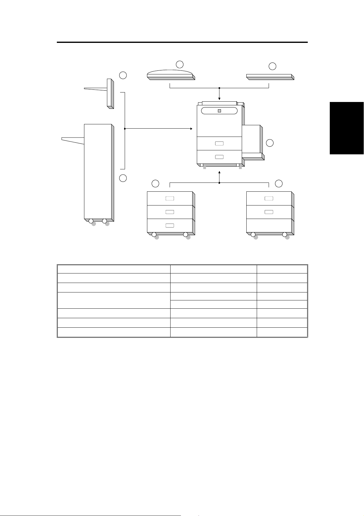
1. MACHINE CONFIGURATION
1
7
6
5 4
2
3
Component
Layout and
Descriptions
Item Machine Code No.
Copier
ADF (Option)
A133 3
A548 (DF61) 1
Paper Feed Unit (Option) A549 (PS290) 5
A550 (PS280) 4
Finisher (Option)
500-sheet Receiving Tray (Option)
Platen Cover (Option)
A612 (SR700) 6
A615(Type D) 7
A381 (Type 540) 2
FSM 2-1 A133/A217
Page 34
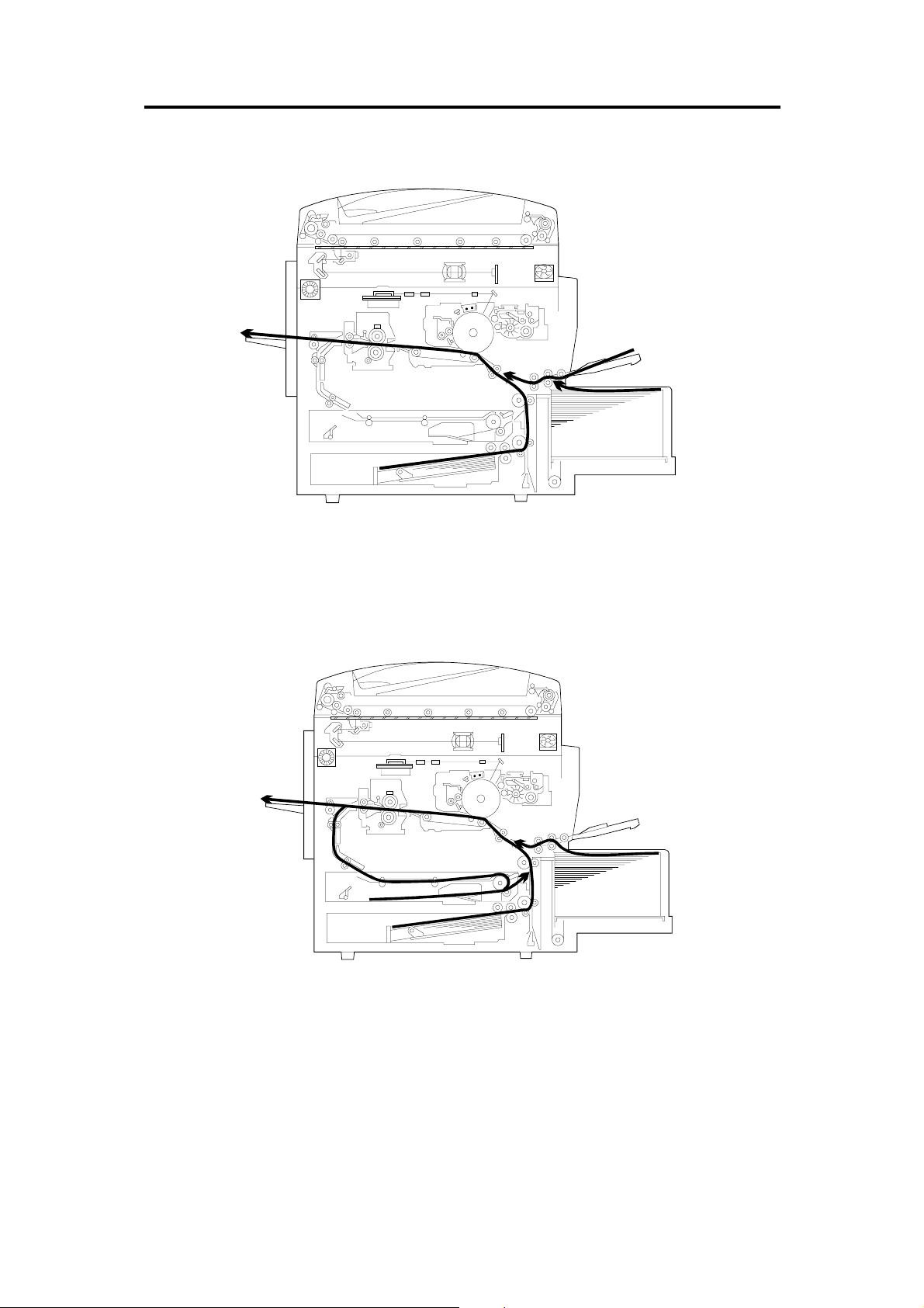
2. PAPER PATH
2.1 NORMAL COPYING
2.2 DUPLEX COPYING
A133/A217 2-2 FSM
Page 35

3. MECHANICAL COMPONENT LAYOUT
9
8
7
10
11
12
13
14
34
35
6
5
4
3
2
1
15
16
Component
Layout and
Descriptions
33
32
31
30
29
28
17
18
19
20
21
23
24252627
22
FSM 2-3 A133/A217
Page 36

1. 3rd. Mirror
22. Feed Roller
2. 2nd. Mirror
3. 1st. Mirror
4. Exposure Lamp
5. Polygonal Mirror Motor
6. Fθ Lenses
7. Cleaning Unit
8. Lens
9. Charge Corona Unit
10. Barrel Toroidal Lens (BTL)
11. CCD
12. Mirror
13. Drum
14. Development Unit
23. Separation Roller
24. Pick-up Roller
25. Duplex Feed Roller
26. Bottom Plate
27. Side Jogger Fen ce
28. Transfer Belt Unit
29. Entrance Rollers
30. End Jogger Fence
31. Pressure Roller
32. Fusing Exit Roller
33. Exit Rollers
34. Hot Roller
35. Optics Exhaust Fan Motor
15. Registration Rollers
16. By-pass Feed Relay Roller
17. By-pass Feed Roller
18. By-pass Pick-up Roller
19. By-pass Separation Roller
20. LCT
21. Relay Rollers
A133/A217 2-4 FSM
Page 37

4. ELECTRICAL COMPONENT DESCRIPTIONS
Refer to the electrical component layout and the point-to-point diagram on
the waterproof paper in the pocket for the locations of these components.
Symbol Index
No.
Printed Circuit Boards
PCB1 90
PCB2 89
PCB3 92
PCB4 93
PCB5 80
PCB6 85
PCB7 87
PCB8 79
PCB9 81
PCB10 84
PCB11 94
PCB12 86
PCB13 83
PCB14 31
PCB15 33
PCB16 40
PCB17 N/A
PCB18 51
PCB19 91
PCB20 7
Motors
M1 57
M2 66
Description Note
SCU (System Control
Unit)
AC Drive Provides ac power to the exposure lamp and
DC Power Supply Provides dc power.
BCU (Base-Engine
Control Unit)
Charge High Voltage
Supply
High Voltage Control Controls the high voltage boards and the
Operation Panel Controls the touch panel display and LED
Scanner Drive Drives the scanner motor.
EX-IPU (Extended
Image Processing
Unit)
SBU (Sensor Board
Unit)
Lamp Stabilizer Provides dc power for the exposure lamp.
Laser
Synchronization
Detector - 1
Laser
Synchronization
Detector - 2
Transfer High
Voltage
Development Bias
Power Pack
Duplex Control Controls the operation of the duplex tray.
Liquid Crystal Display Controls the guidance display and displays
LCT Interface Interfaces the LCT control signal between
Relay Board Switches ac power to either the dc drive
Laser Diode Drive Controls the laser diode.
Main Drives the main body components.
Toner Bottle Drive Rotates the toner bottle to supply toner to
Controls all copier functions, directly or
through other control boards.
fusing lamps.
Controls the mechanical parts of the printer.
Supplies high voltage to the charge corona
unit.
quenching lamp.
matrix, and monitors the key matrix.
Processes the video signal from the SBU
and sends the video signal to the LD unit.
Contains the CCD, and outputs a video
signal to the EX-IPU board.
Detects the laser beam at the start of the
main scan.
Detects the laser beam at the end of the
main scan.
Supplies high voltage to the transfer belt.
Supplies high voltage to the development
roller.
guidance for machine operation.
the main board and the LCT.
board (if the main switch is on) or to the
heaters (if the main switch is off).
the toner supply unit.
Component
Layout and
Descriptions
FSM 2-5 A133/A217
Page 38

Symbol Index
No.
M3 73
Description Note
Tray Lift Raises the bottom plate in the paper tray.
M4 56
M5 48
M6 74
M7 65
M8 78
M9 60
M10 55
M11 36
M12 39
M13 38
M14 75
M15 68
Sensors
S1 13
S2 15
S3 18
S4 46
S5 16
S6 47
S7 49
S8 50
S9 12
S10 19
S11 29
S12 30
Polygonal Mirror Turns the polygonal mirror.
LCT Lift Lifts up and lowers the LCT bottom plate.
Optics Exhaust Fan Removes heat from the optics unit.
IPU Fan Removes heat from the IPU board.
Exhaust Fan Removes heat from around the fusing unit.
Ozone Fan Removes ozone-laden air from inside the
machine.
Scanner Drive Drives the 1st and 2nd scanners (dc stepper
motor).
Duplex Feed Drives the feed roller and moves the bottom
plate up and down.
End Fence Jogger Drives the end fence jogger to square the
paper stack.
Side Fence Jogger Drives the side fence jogger to square the
paper stack.
DC Drive Board Fan Removes heat from around the DC drive
board.
Charge Inlet Fan Provides air flow around the charge corona
unit section.
By-pass Feed Paper
Width
By-pass Feed Paper
End
Tray Paper End Informs the CPU when the paper tray runs
Upper Relay Detects the leading edge of paper from the
Tray Upper Limit Detects the height of the paper stack in the
Lower Relay Detects misfeeds.
LCT Lower Limit Sends a signal to the CPU to stop lowering
LCT Paper End Informs the CPU when the LCT runs out of
LCT Upper Limit Signals the CPU to stop lifting the LCT
Registration Detects the leading edge of the copy paper
Image Density
(ID)
Toner Density
(TD)
Informs the CPU what width paper is in the
by-pass feed table.
Informs the CPU that there is no paper in the
by-pass tray.
out of paper.
paper tray and duplex unit to determine the
stop timing of the paper feed clutch and
duplex feed motor. Also detects misfeeds.
paper tray to stop the upper tray lift motor.
the LCT bottom plate.
paper.
bottom plate.
to determine the stop timing of the paper
feed clutch, and detects misfeeds.
Detects the density of various patterns on
the drum during process control.
Detects the amount of toner inside the
development unit.
A133/A217 2-6 FSM
Page 39

Symbol Index
No.
S13 1
S14 8
S15 9
S16 24
S17 6
S18 32
S19 28
S20 10
S21 2
S22 34
S23 35
S24 42
S25 37
S26 41
S27 23
S28 14
Switches
SW1 11
SW2 53
SW3 20
SW4 54
SW5 52
SW6 27
SW7 26
Magnetic Clutches
CL1 61
CL2 59
Description Note
Scanner HP Informs the CPU when the 1st and 2nd
scanners are at the home position.
Original Length-1 Detects the length of the original. This is one
of the APS (Auto Paper Select) sensors.
Original Length-2 Detects the length of the original. This is one
of the APS (Auto Paper Select) sensors.
Fusing Exit Detects misfeeds.
Platen Cover Informs the CPU whether the platen cover is
up or down (related to APS/ARE functions).
ARE: Auto Reduce and Enlarge
Toner End Instructs the CPU to add toner to the toner
supply unit, and detects toner end conditions.
Auto Response Returns the operation panel display and
exits from the energy saver mode.
Transfer Belt
Position
Original Width Detects the width of the original. This is one
Duplex Paper End Detects paper in the duplex tray.
Duplex Turn Detects the trailing edge of the copy paper
Duplex Entrance Detects misfeeds.
Side Fence Jogger
HP
End Fence Jogger
HP
Toner Overflow Detects when the used toner collection
By-pass Relay Detects misfeeds.
By-pass Feed Table Detects whether the by-pass feed table is
Tray Down Sends a signal to the CPU to lower the LCT
Tray Paper Size Determines what size of paper is in the
LCT Cuts the dc power line and detects whether
LCT Cover Cuts the dc power line of the LCT lift motor.
Main Supplies power to the copier.
Front Cover Safety Cuts the dc power line and detects whether
Toner Supply Turns the toner supply roller to supply toner
Development Drives the development roller.
Informs the CPU of the current position of
the transfer belt unit.
of the APS (Auto Paper Select) sensors.
to determine the jogging timing, and detects
misfeeds.
Detects the home position of the duplex side
fence jogger.
Detects the home position of the duplex end
fence jogger.
bottle is full.
open or closed.
bottom plate.
paper tray.
the LCT is open or not.
the front cover is open or not.
to the development unit.
Component
Layout and
Descriptions
FSM 2-7 A133/A217
Page 40

Symbol Index
CL3 76
CL4 58
CL5 63
CL6 71
CL7 72
CL8 62
Solenoids
SOL1 67
SOL2 77
SOL3 64
SOL4 69
SOL5 70
Lamps
L1 3
L2 43
L3 88
Description Note
No.
Transfer Belt Lift Controls the touch and release movement of
the transfer belt unit.
Registration Drives the registration rollers.
By-pass Feed Starts paper feed from the by-pass feed
table or LCT.
Relay Drives the relay rollers.
Paper Feed Starts paper feed from the paper tray.
By-pass Relay Drives the by-pass relay rollers.
By-pass Pick-up Drops the pick-up roller to the by-pass paper
feed position. When paper is fed from the
LCT, this solenoid assists SOL3.
Junction Gate Moves the junction gate to direct copies to
the duplex tray or to the paper exit.
LCT Pick-up Drops the pick-up roller all the way down to
the LCT paper feed position from the
by-pass paper feed position.
Pick-up Controls the up/down movement of the
pick-up roller in the paper tray.
Separation Controls the up/down movement of the
separation roller at the paper tray feed
station.
Exposure Applies high intensity light to the original for
exposure.
Fusing Provides heat to the hot roller.
Quenching Neutralizes any charge remaining on the
drum surface after cleaning.
Heaters
H1 21
H2 5
H3 22
Thermistors
TH1 45
Thermofuses
TF1 44
Thermoswitch
TS1 4
Drum (option) Turns on when the main switch is off to
prevent moisture from forming around the
drum.
Optics
Anti-condensation
(option)
Tray
(option)
Fusing Monitors the temperature at the central area
Fusing Provides back-up overheat protection in the
Exposure Lamp Opens the exposure lamp circuit if the 1st
Turns on when the main switch is off to
prevent moisture from forming on the optics.
Turns on when the main switch is off to keep
paper dry in the paper tray.
of the hot roller.
fusing unit.
scanner overheats.
A133/A217 2-8 FSM
Page 41

Symbol Index
Counters
CO1 25
CO2 N/A
Others
CB1 17
HDD 82
Description Note
No.
Total Keeps track of the total number of copies
made.
Key
(option)
Circuit Breaker
(220 ~ 240V
machines only)
Hard Disk Drive Scanned image data is compressed and
Used for control of authorized use. The
copier will not operate until it is installed,
when this option is enabled.
Provides back-up high current protection for
electrical components.
held here temporarily during copying; also
holds user stamp data.
Component
Layout and
Descriptions
FSM 2-9 A133/A217
Page 42

5. DRIVE LAYOUT
15
14
13
1
2
12
3
11
10
4
9
5
6
7
8
1. Toner Supply Clutch
2. Development Clutch
3. Drum Drive Pulley
4. Main Motor
5. Scanner Drive Motor
6. Fusing Drive Gear
7. Exit Drive Gear
8. Toner Collection Bottle Drive Gear
9. Transfer Belt Drive Gear
10. Cleaning Blade Drive Gear
11. Registration Clutch
12. Paper Feed Clutch
13. Relay Clutch
14. By-pass Feed Clutch
15. By-pass Relay Clutch
A133/A217 2-10 FSM
Page 43

INSTALLATION PROCEDURE
Page 44

Page 45

1. INSTALLATION REQUIREMENTS
1.1 ENVIRONMENT
1. Temperature Range: 50°F ~ 86°F (10°C ~ 30°C)
2. Humidity Range: 15% ~ 90%
3. Ambient Illumin at i on : Le ss tha n 1,500 lux (Do not expose to di r e ct
sunlight.)
4. Ventilation: 30 m3/hr/person
5. Ambient Dust: Less than 0.10 mg/m3 (2.7 x 10⁻⁶ oz/yd3)
6. If the place of instal lation is air-condi tio ne d or he ated, place the machi ne :
a) where it will not be subjected to sudden temperature changes.
b) where it will not be directly exposed to cool air from an air conditioner.
c) where it will not be directly exposed to heat from a heater.
7. Do not place the machine where it will be exposed to corrosive gases.
8. Do not install the machine at any location over 2,000 m (6,500 feet)
above sea level.
Installation
Procedure
9. Place the copier on a strong and level base.
10. Do not place the machine where it may be subjected to strong vibration.
1.2 MACHINE LEVEL
1. Front to back: Within 5 mm (0.2") of level
2. Right to Left: Within 5 mm (0.2") of level
FSM 3-1 A133/A217
Page 46

1.3 MINIMUM SPACE REQUIREMENTS
Place the copier near a po wer source, providing clearance as shown.
– Copier –
More than 10 cm or 3.9"
More than 50 cm or 19.7"More than 39 cm or
15.4"
– Copier with the optional finisher–
More than 70 cm ro
27.6"
More than 10 cm or 3.9"
More than 72 cm or 28.3"
More than 50 cm or
19.7"
More than 70 cm
1.4 POWER REQUIRMENTS
CAUTION
+
A. Be sure to ground the machine.
B. Make sure the plug is firmly inserted in the outlet.
C. Avoid multi-wiring.
1. Input voltage level:
120V, 60Hz: More than 12A
2. Permissible voltage fluctuation: ±10%
3. Do not set anything on the power cord.
A133/A217 3-2 FSM
Page 47

2. COPIER INSTALLATION
2.1 ACCESSORY CHECK
Check the quantity and condi tio n of the accessories in the box against the
following list:
Description Qt’y
1. Paper Size Decal ................................................... 1
2. Operating Instructions (except for -27 machines) .. 1
3. New Equipment Condition Report ..........................1
4. User Survey Card (-17 machines only) .................. 1
Installation
Procedure
FSM 3-3 A133/A217
Page 48
[F]
[E]
[B]
[C]
[D]
[A]
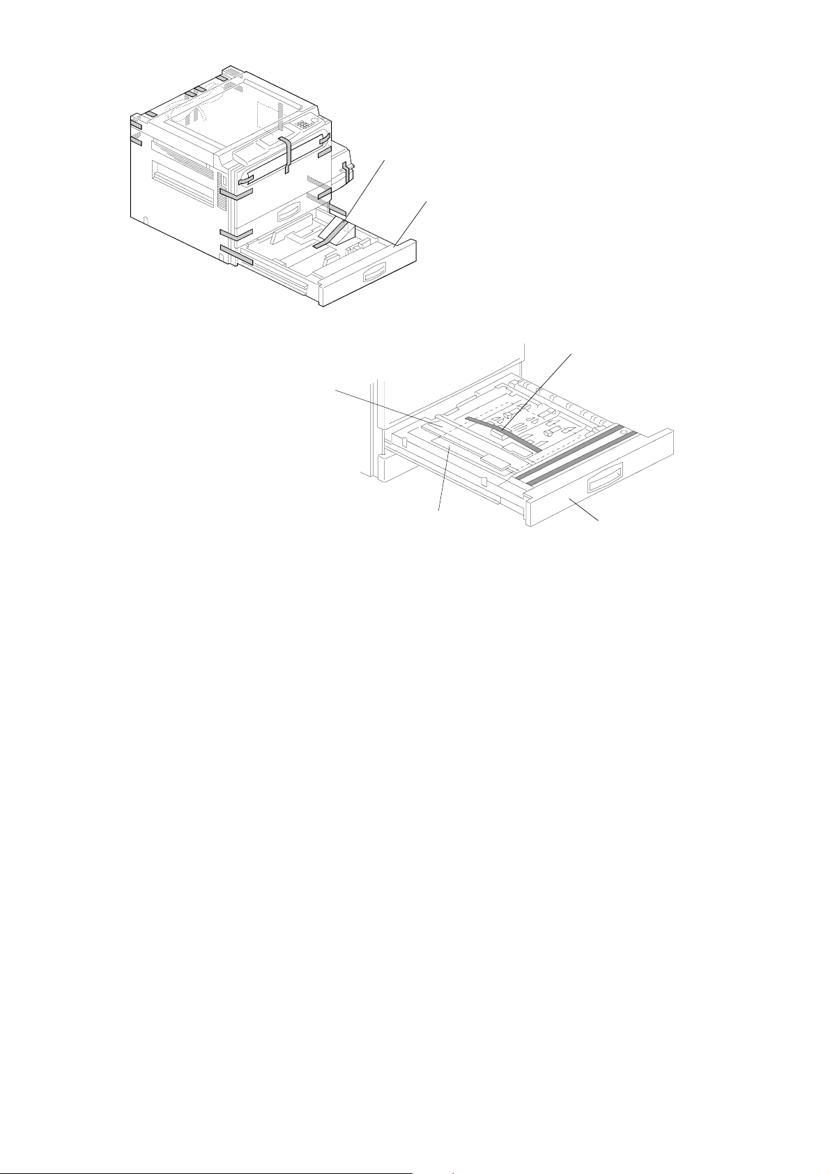
NOTE: 1) Keep the shipping retainers after installing the machine. They
will be reused if the machine is moved to another location in
the future.
2) Never lift the machine by holding the LCT, or the LCT will
break.
1. Remove the strips of tape.
2. Pull out the duplex tray [A] and remove the strips of tape.
3. Remove the guide rolle r stop pe r [B] .
4. Open the lower duplex guide plate [C] and remove the sheets of paper
[D]and the styrofoam.
5. Install the duplex tray i n th e m achi ne .
6. Pull out the paper tray [E], and remove the strips of tape and the bottom
plate stopper [F]. The n inst all th e pa pe r tray i n the m ach ine .
A133/A217 3-4 FSM
Page 49

[D]
[B]
[F]
[A]
[B]
[B]
[E]
[C]
[G]
[L]
[J]
[I]
[K]
[H]
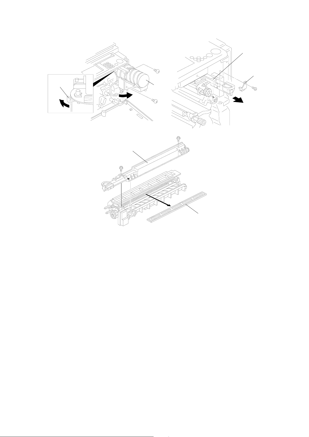
7. Open the front cover and swing out the toner bottle holder [A].
8. Remove the strips of tape [B].
9. Remove transfer belt release pin [C] and cleaning blade release pin [D].
Installation
Procedure
NOTE: Put back pins [C] and [D] before transporting the machine to a
new location.
10. Turn the "A1" lever [E] counterclockwise to lower the transfer belt unit.
11. Remove the charge corona unit [F] (1 screw).
12. Remove the toner collection bottle [G] (1 connector).
13. Remove the drum knob (turn clockwise) [H] and drum bushing [I].
14. Disconnect the ID sensor harness [J] and carefully slide out the drum
unit [K] until t he front guide plate rele ase s fr om th e po si tioning pins.
15. Move the development unit [L] to the right - away from the drum, then
slide out the drum unit completely. Be careful not to scratch the Drum.
FSM 3-5 A133/A217
Page 50
[D]
[C]
[B]
[A]
[E]
[F]
16. Remove the toner bottle holder [A] (2 screws, 1 connector).
17. Turn the shutter lever [B] of the toner bottle holder as shown to prevent
toner from spilling.
18. Remove the development unit stopper [C] (1 screw).
19. Pull out the development unit [D] (1 connector). Be careful not to catch
the wire harness on the fram scr ew, on th e r igh t si de of the m ach ine .
Place the development unit on a clean sheet of paper.
20. Remove the toner supply unit [E] (2 screws, 1 connect or) If necessa ry,
remove the shipping tape from the front and back sides of the
development unit.
21. Remove the development filter [F].
A133/A217 3-6 FSM
Page 51

[A]
[B]
[C]
[D]
22. Pour about half a pack of developer [A] into the development unit. Then
rotate the knob [B] as shown to distribute the developer evenly. Then
pour in all the remaining developer and rotate the knob again.
NOTE: To prevent the developer from spilling, do not rotate the knob in
the other direction.
23. Replace the dev. filter. Attach the toner supply unit to the dev. unit.
24. Install the development unit in the copier and put back the stopper ([C]
that was removed in step 18).
NOTE: Be careful not to damage the bias wire on the frame screw.
25. Move the develo pme nt uni t to th e r igh t so th at the deve l op men t un i t is
away from the drum. Then install the drum un i t. Do no t scratch the drum.
26. Install the toner bottle holder, making sure that the toner bottle holder
[C] and bracket [D] are at right angles as shown above. If not, swing the
toner bottle holder out in the direction of the big arrow in the diagram.
27. Turn the "A1" lever clockwise to raise the transfer belt unit.
28. Install the charge cor ona un i t. Do not scratch the OPC drum.
Installation
Procedure
29. Install the toner collection bottle.
30. Install the toner bottle by following the instructions on the reverse side of
the front cover.
31. Swing the toner bottle holder into its original position and close the front
cover.
FSM 3-7 A133/A217
Page 52
[E]
[G]
[H]
[F]
[I]
[G]
[H]
[A]
[C]
[B]
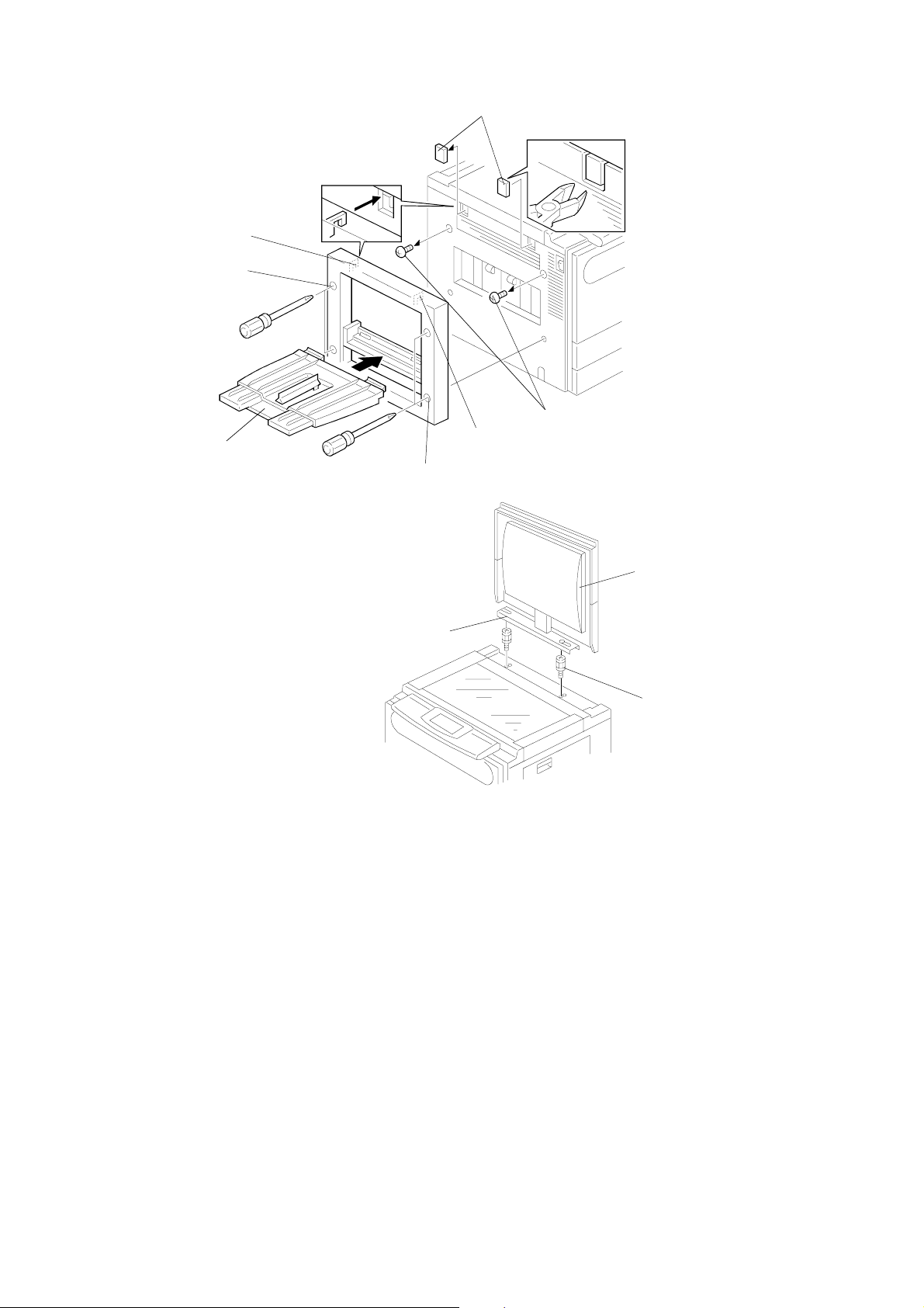
32. Install the 500-sh ee t cop y tr ay i f req uir e d:
1) Remove caps [E] with wire cutters.
2) First, remove the screws [F], and fit the hooks [G] on the copy tray unit
into the openings. Then tighten the screws [H] that are built into the
copy tray unit.
3) Install the copy tray [I].
33. Install the optional platen cover [A] as shown if required :
1) Install two stud screws [B] on the top cover.
2) Position the platen cover bracket [C] on the stud screws and slide it to
the left.
A133/A217 3-8 FSM
Page 53

SCU
MSIS
IC 411
IC 412
COPY1
IC 413
COPY2
For USA models, proceed to step 37. Steps 34 through 36 are for the
220 ~ 240 V machine only.
34. Remove the rear cover.
35. Install the three ROMs which contain the language kit in the IC411,
IC412, and IC413 sockets on the SCU board (the lower left PCB as
viewed from the rear of the machine).
The "MSIS" ROM should be put in the IC411 socket.
The "COPY1" ROM should be put in the IC41 2 socke t.
The "COPY2" ROM should be put in the IC41 3 socke t.
NOTE: Do not bend the pins of the ROMs.
Do not install the ROMs the wrong way round.
36. Put the rear cover back on the machine.
37. Plug in the copier and turn on the main switch.
38. After the mach i ne reach es th e op er a ti o n con di t i on (t he star t but to n LED
is green), enter SP mode as follows:
1) Press the "Clear Modes" key.
2) Enter "107" usin g th e numeric keys.
3) Hold down the "Clear/Stop" key for more th an 3 secon ds.
Installation
Procedure
39. Perform the TD sensor initial setting as follows:
1) Enter "2801" and press the "Enter" key.
2) Touch "Start" on the LCD.
NOTE: The machine will automatically stop when TD sensor initial
setting is completed.
FSM 3-9 A133/A217
Page 54

[B]
On the paper tray
On the duplex tray
[A]
40. Perform the free run procedure as follows:
1) Enter "5802" and press the "Enter" key.
2) Touch "ON" on the LCD then touch "Copy Mode" on the LCD.
3) Set the number of cop i es at 50.
4) Close the platen cover or the ADF then press the "Start" key.
5) After finishing the free run, touch "SP Mode" on the LCD.
6) Touch "Quit" on the LCD to leave SP mode.
41. Pull out the paper tray and load paper into it (the paper size and
orientation should be as specified by the customer).
NOTE: The side and rear fences should be properly positioned.
42. Select the appropriate paper size for th e paper tray by sliding the paper
size slider [A] into the correct position.
NOTE: A non-standard pa pe r size can be select ed with a UP mode
(See the Paper Size Selection section).
43. When the optional Paper Feed Unit is installed: Ent er th e pr o pe r
paper size for each pape r tray using a UP mode. (See the Paper Size
Selection section.)
44. Attach the appropr iate paper size decals [B] to the pa pe r trays. Al so,
attach the duplex decal to the duplex tray.
NOTE: Paper size decals are also used for the optional paper feed unit.
Keep any remaining decals for use with the paper feed unit.
45. Check the copy quality and machine operation.
A133/A217 3-10 FSM
Page 55

2.2 KEY COUNTER (OPTION)
[F]
[D]
[E]
[G]
[C]
[A]
[B]
Installation
Procedure
CAUTION
+
Unplug the copier power cord before starting the following procedure.
1. Remove the right cover [A]. (See "Replacement and Adjustment - Outer
Cover Removal".)
2. Remove the cap [B] with wire cutters.
3. Remove the key counter cover [C] (2 screws)
4. Pass the key counter holder conn ector [D] through th e op en ing [ E] .
5. Disconnect the connector [F] and connect the key counter holder
connector.
6. Mount the key counter holder [G] (2 screws).
7. Reassemble the machine and check the key counter’s operation.
FSM 3-11 A133/A217
Page 56

2.3 TRAY HEATER (OPTION)
[C]
[A]
CAUTION
+
Unplug the copier power cord before starting the following procedure.
1. Remove the duplex unit. (See "Replacemen t an d Ad j ust m en t - Dupl e x
Unit Removal".)
[B]
2. Remove the paper feed tray. (See "Replacement and Adjustment Paper Feed Tray Removal".)
3. Install the tray he ater [A] (2 screws).
4. Connect the connector of the hea te r to th e cop i er ’s con ne cto r [B] which
is mounted on the rear frame.
5. Fit the heater harness into the cable clamp.
6. Install the heater cover [C ] (1 scr ew) .
7. Reassemble the machine.
8. Check the printer side-to-side registration for the 1st paper feed station
(SP1002-2) and the duplex unit (SP1002-1).
NOTE:
Tell the customer that even when the copier’s main switch is
turned off, the copier power cord should be plugged in.
Otherwise, the tray heater will not function.
A133/A217 3-12 FSM
Page 57

2.4 DRUM HEATER (OPTION)
[B]
[C]
[D]
[A]
CAUTION
+
Unplug the copier power cord before starting the following procedure.
Installation
Procedure
1. Remove the transfer th e belt unit. (See "Replacement and Adjustment Transfer Belt Unit Removal".)
2. Move the "A1" lever clockwise.
3. Install the drum heater [A ] (2 screws).
4. Connect the connector of the hea te r to th e cop i er ’s con ne cto r [B] which
is mounted on the rear frame.
5. Fit the heater harness into the cable clamp.
NOTE:
6. Install the heater cover [D ] (1 scr ew) .
7. Reassemble the machine.
NOTE:
Route the heater ha rness under the hook [C].
Tell the customer that even when the copier’s main switch is
turned off, the copier power cord should be plugged in.
Otherwise, the drum heater will not function.
FSM 3-13 A133/A217
Page 58

2.5 OPTICS ANTI-CONDENSATION HEATER (OPTION)
[B]
[C]
CAUTION
+
Unplug the copier power cord before starting the following procedure.
1. Remove the exposure glass. (See "Replacement and Adjustment Exposure Glass Removal".)
[A]
2. Move the 1st scanner to the cent er of the scann er un i t.
3. Install the optics anti -condensation heater [A] (2 scwers).
4. Connect the connector of the hea te r to th e cop i er ’s con ne cto r [B] which
is mounted on the front frame of the scanner unit.
5. Fit the harness into the clamper [C].
6. Reassemble the machine.
NOTE:
Tell the customer that even when the copier’s main switch is
turned off, the copier power cord should be plugged in.
Otherwise, the optics anti-condensation heater will not function.
A133/A217 3-14 FSM
Page 59
3. PAPER SIZE SELECTION
3.1 OPTIONAL PAPER FEED UNIT
The paper size for the pa pe r fee d un i t can be selected with User Prog r am
mode.
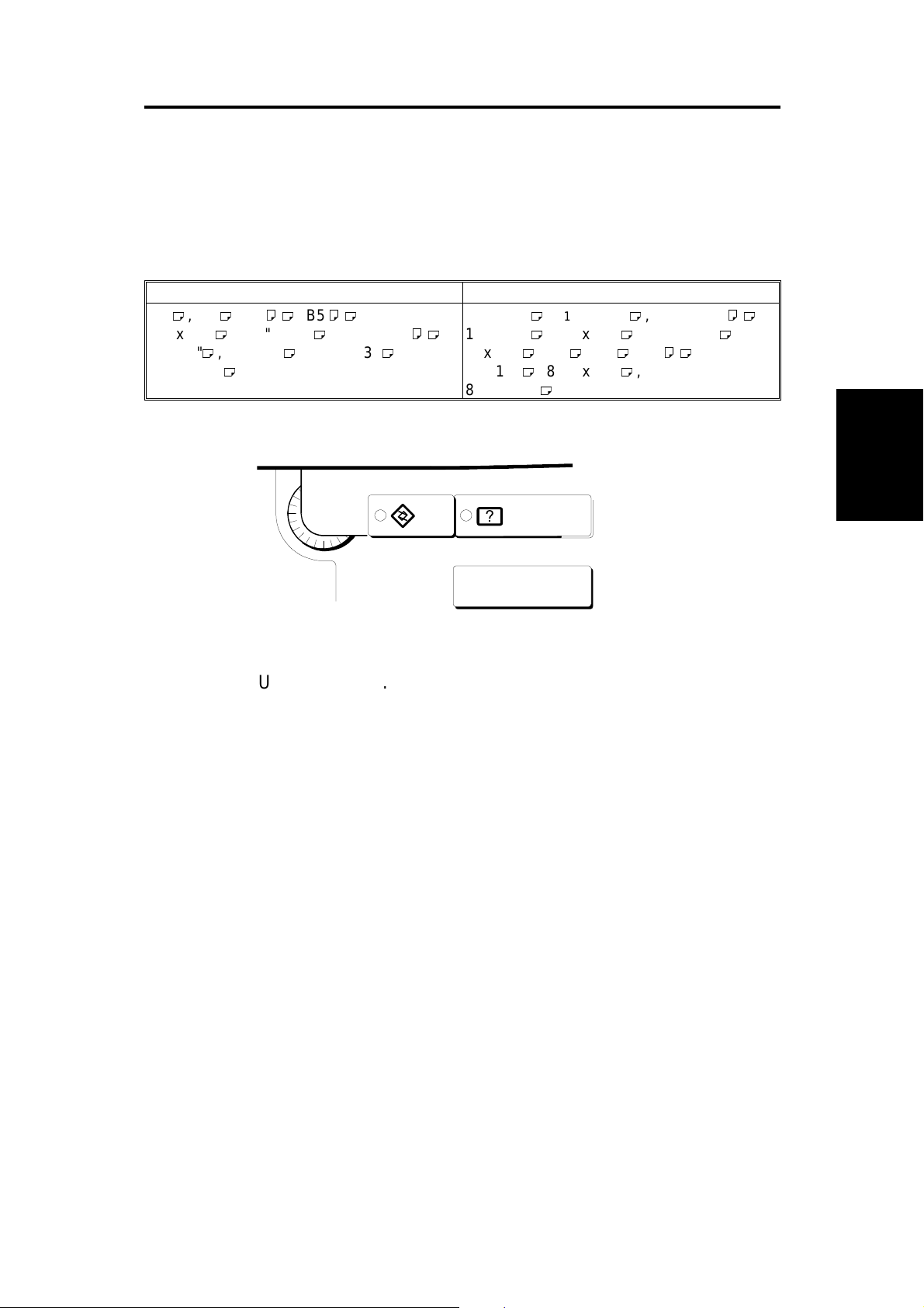
You can select paper of the following sizes:
Metric version Inch version
, B4 , A4
A3
11" x 17" , 8
8" x 10", 8" x 13" , 8
" x 13"
8
1/4
1/2
, B5
" x 14" , 8
1/2
" x 13" ,
1/2
" x 11"
11" x 17" , 8
,
11" x 15" , 10" x 14" , 8" x 10
8" x 10" , A3 , B4 , A4
8" x 13" , 8
" x 13"
8
1/4
1/2
1/2
" x 14" , 8
" x 13" ,
" x 11"
1/2
1/2
,
" ,
,
User Tools
Guidance
1. Press the User Tools key.
2. Touch the Basic Settings key.
3. Touch the Next key three times to reach the paper size setting menu.
4. Find the paper tray (2, 3, or 4) an d to uch the Ch an ge key. Se lect the new
paper size by touching a key. Then touch the Exit key.
5. Press the User Tools key.
Installation
Procedure
FSM 3-15 A133/A217
Page 60

3.2 1ST TRAY - NON-STANDARD PAPER SIZE SELECTION
For the 1st tray, a wider range of paper sizes can be selected with Us er
Program mode.
If a non-standard paper size is selected, the machin e ign ores the paper size
set with the paper size slider.
You can select paper of the following sizes:
Metric version Inch version
11" x 17" , 8
8" x 10"
" x 14" , 5
1/2
1/2
" x 8
1/2
" ,
11" x 15" , 10" x 14" , 8" x 10
1/2
"
User Tools
Guidance
[A]
1. Slide the paper size slider [A] on the paper tray into the "*" position.
2. Press the User Tools key.
3. Touch the Basic Setting key.
4. Touch the Next key three times to reach the paper setting menu.
5. In the Tray <*> Paper Size Se tting menu, the pres en t size setting is
displayed. Touch the Change key. Select the new paper size by touching
a key. Then, touch the Exit key.
6. Press the User Tools key.
A133/A217 3-16 FSM
Page 61

3.3 1ST TRAY - F/F4 SIZE PAPER SELECTION
For the 1st tray, a wider range of F and F4 paper sizes can be selected with
User Program mode.
You can select paper of the following sizes:
8" x 13"
8
" x 13"
1/4
8
" x 13"
1/2
User Tools
Guidance
[A]
1. Slide the paper size slider [A] on the paper tray into the "F/F4" position.
2. Press the User Tools key.
3. Touch the Basic Setting key.
Installation
Procedure
4. Touch the Next key three times to reach the paper setting menu.
5. In the Tray <F/F4> Paper Size Se tting menu, the present s ize setting is
displayed. Touch the Change key. Select the new paper size by touching
a key. Then, touch the Exit key.
6. Press the User Tools key.
FSM 3-17 A133/A217
Page 62

Page 63

SERVICE TABLES
Page 64

Page 65

1. SERVICE REMARKS
1.1 GENERAL CAUTION
Do not turn off the main switch while any of the electrical compon ents are
active. Doing so might cause damage to units such as the transfer belt,
drum, and development unit when they are pulled out of or put back into the
copier.
1.2 DRUM
The organic photoconductor (OPC) drum is more sensitive to light and
ammonia gas than a sel e niu m drum . Fol low th e cau tio ns be l ow w he n
handling an OPC dr um.
1. Never expose the drum to direct sunlight.
2. Never expose the drum to direct light of more than 1,000 Lux for more
than a minute.
3. Never touch the drum surface with bare hand s. Whe n th e dr u m sur fa ce
is touched with a finger or beco mes di rty, wipe it with a dry cloth or cl ea n
it with wet cotton. Wipe with a dry cloth after cleaning with wet cotton.
4. Never use alcohol to clean the drum; alcohol diss olves the drum surface.
5. Store the drum in a cool, dry place away from heat.
6. Take care not to scratch the drum as the dr um l aye r is th in an d is easily
damaged.
7. Never expose the drum to corrosive gases such as ammonia gas.
8. Always keep the drum in the protective sheet when keeping the drum
unit, or the drum itsel f , ou t of the copie r . D oin g so avo ids exp osi n g it to
bright light or direct sunlight. This will protect the drum from light fatigue.
9. Before pulling out the drum unit, place a sheet of paper under the drum
to catch any spilt toner.
10. Dispose of used drums in accordance with local regulations.
Tables
Service
FSM 4-1 A133/A217
Page 66

Rev. 6/96
11. When installing a new drum in the drum unit, the following must be done.
a) Remove the protective sheet after securing the new drum to the drum
unit.
b) Do the ID Sensor Initial Setting procedure (SP Test Mode 3001).
12. When the drum unit is removed, push the development unit to the right
before re-installing the drum unit.
1.3 TRANSFER BELT UNIT
1. Replace the transfer belt every two PM cycles (240K copies) to avo id
bad effects on the drum.
2. Never touch the transfer belt surface with bare hands.
3. Take care not to scratch the transf er be lt as th e sur f ace is easi ly
damaged.
4. Before installing the new transfer belt, clean all the rollers with a dry cloth
to prevent the bel t fr o m slip pi n g.
1.4 SCANNER UNIT
1. When installing the exposure glass, make sure that the white reference
plate is facing dow n.
2. Clean the exposure glass with alcohol or glass cleaner to reduce the
amount of static electric ity on the glass surface.
3. Use a cotton pad with water or a blower brush to clean the mirrors and
lens.
4. Do not bend or crease the exposure l amp fl at cable .
5. Do not disassemble the lens unit. Doing so will throw the lens and the
copy image out of focus.
6. Do not turn any of the CCD positioning screws. Doing so will throw the
CCD out of position.
A133/A217 4-2 FSM
Page 67

1.5 LASER UNIT
1. Do not loosen the screws that secure the LD drive board to the laser
diode casing. Doing so would throw the LD unit out of adjustment.
2. Do not adjust the variable resistors on the LD unit, as they are adjusted
in the factory .
3. The polygon mirror and F-theta lenses are very sensitive to dust. Never
open the optical housing unit or remove the polygon mirror motor cover.
4. Do not touch the glass surface of the polygon mirror mot or unit with bare
hands.
1.6 CHARGE CORONA UNIT
1. Clean the charge corona wire with a dry cloth. Do not use sandpaper or
a solvent.
2. Clean the charge corona casing with wet cotton and a dry cloth.
3. Clean the end blocks with a blower brush first to remove toner and paper
dust. Then clean it with a dry cloth if any toner still remains on it.
4. Do not touch the corona wir e s with bare hands. Oil stai ns fr o m f ing er s
may cause uneven image density on copies.
5. Make sure that there is no foreign material (iron filings, etc.) on the
casing.
6. To avoid uneven charge, do not bend or scratch the wire surface when
installing new corona wires. Also be sure that the corona wires are
correctly positioned in the grooves of the end blocks.
7. Clean the charge grid pla te with a blower brush, water, then with a dry
cloth. When doing so, be careful not to damage the grids by letting fibers
attach to them.
8. Do not touch the charge gr id pl a te wit h bare hands. Also, do not ben d
the charge grid pl at e or make any de nt in it. Doing so may cause un eve n
charge.
1.7 DEVELOPMENT
1. Be careful not to nick or scratch the development ro ll er s.
Tables
Service
2. Place the development unit on a sheet of paper after removing it from the
copier.
3. Never disassemble the develo pm e nt rol ler asse mbl y. The po siti o n of the
doctor plate is set with spe c ial to ol s an d inst r ume nts at the factory to
ensure the proper gap between the doctor blade and the development
roller.
FSM 4-3 A133/A217
Page 68

4. Clean the drive gears after removing used developer.
5. Dispose of used developer in accordance with local regulations.
6. When removing or installing the development unit, be careful not to
damage the drum surface with the entrance seal on the development unit.
7. Never load different types of developer and toner into the development
unit. Doing so will cause poor copy quality and toner scattering.
8. Immediately after installing new developer, the TD sensor initial setting
procedure should be performed to avoid damage to the copier. Do not
perform the TD sensor initial setting with used developer. Do not make
any copies before doing the TD sensor initial setting.
9. When using a vacuum cleaner to clean the develo pment unit casing,
always ground the casing with your fingers to avoid damaging the toner
density sensor with static electricity.
10. After replacing th e TD senso r, do the TD sens or i nit i al set ti n g pro c ed ure
(SP 2801).
1.8 DRUM CLEANING
1. Do not touch the cleaning brush with bare hands.
2. When servicing the cleaning section, be careful not to damage the edge
of the cleaning bla de .
1.9 FUSING UNIT
1. After installing the fusing thermistor, make sure that it is in contact with
the hot roller and that it is movable.
2. Be careful not to damag e th e ed ge s of the hot roller stripp er s or th ei r
tension springs.
3. Do not touch the fusing lamp and rollers with bare hands.
4. Make sure that the fusing lam p is positioned correctly and that i t do es no t
touch the inner surface of the hot roller .
A133/A217 4-4 FSM
Page 69

1.10 PAPER FEED
1. Do not touch the surface of the pick-up, feed, and separation rollers.
2. The side fences and end fence of th e paper tray must be positi o ne d
correctly to align with the actu al pa pe r size to avo i d pa pe r misf ee ds.
1.11 USED TONER
1. The used toner tank should be emptied at every PM cycle, but we
recommend checking the amount of used toner in the tank at every EM.
2. When reinstalling the used toner tank, make sure that the toner overflow
sensor connector is inserted firmly.
3. Dispose of used toner in accordance with local regulations. Never throw
toner into an open flame, for toner dust may ignite when exposed to
open flame.
1.12 OTHERS
1. When carrying the copier, never lift it up by holding the LCT. Otherwise,
the LCT will be broken. Hold the copier by the carrier handles in the
bottom corners.
2. Do not move the copier while the main switch is on. The hard disk will be
damaged. Stop the hard disk from spinning with SP 4911-4 before
moving the machine.
Tables
Service
FSM 4-5 A133/A217
Page 70

2. SERVICE PROGRAM MODE
2.1 SERVICE PROGRAM MODE OPERATION
The service program (SP) mode is used to check electrical data, change
modes, and adjust value s.
2.1.1 Service Program Access Procedure
1) How to enter the SP mode
Press the following keys in sequence.
Hold the
A menu of SP modes is displayed on the screen.
2) How to use an SP mode
Input the required SP mode number at the ten-key pad, then press Enter (#).
Also, you can scroll through the modes on the screen by pressing the "Prev.
SP" or "Next SP" button.
To get to a Class 2 level, press the Enter key again. Then scroll through the
Class 2 modes with "Prev. SP" or "Next SP".
3) How to return to the main menu from within an SP mode
Press the
4) How to leave SP mode
Touch the "Quit" button on the display.
→
key for more tha n 3 second s.
key.
→
→
!
→
A133/A217 4-6 FSM
Page 71

2.1.2 Accessing Copy Mode from within an SP Mode
[A]
[B]
1. Touch "Copy Mode" [A] on the display. (This now changes to "SP Mode".)
2. Select the appropriate copy m od es and m ake tr ial cop ies.
3. To return to the SP mode, touch "SP Mode" [B] on the display.
2.1.3 To Input a Value or Setting for an SP Mode
1. Input the value using the number key s, or for some SP modes, press the
appropriate setting button on the scr ee n.
2. If you used the number keys, now press the "Enter" key.
NOTE:
If you forget to press the "Enter" key, the previous value remains.
Tables
Service
FSM 4-7 A133/A217
Page 72

2.2 SERVICE PROGRAM MODE TABLES
2.2.1 MAIN SP MODE TABLE
NOTE:
1. In the Function column, comments are in italics.
2. In the Settings column, the default value is in bold letters.
3. An asterisk " * " after the mode number means that this mode is
stored in the NVRAM. If you do a RAM reset, all these SP modes
will be reset to their factory settings.
Mode No.
Class 1 Class 2
1001 * Leading Edge
Registration
1002 * 1 * Side-to-Side
Registration
(Duplex)
2 * Side-to-Side
Registration
(1st paper
feed)
3 * Side-to-Side
Registration
(2nd paper
feed: Option
PFU tray 1)
4 * Side-to-Side
Registration
(3rd paper
feed: Option
PFU tray 2)
5 * Side-to-Side
Registration
(4th paper
feed: Option
PFU tray 3 if
present)
Function Settings
Adjusts the printing leading edge
registration using Trimming Area Pattern
(SP2902-3, No.10).
Use the
The specification is 3
•/∗
key to toggle between + and -.
±
2 mm. See
"Replacement and Adjustment - Copy
Image Adjustments" for details.
Adjusts the printing side-to-side
registration from the duplex tray using the
Trimming Area Pattern (SP2902-3,
No.10).
Use the
The specification is 2
•/∗
key to toggle between + and -.
±
1.5 mm. See
"Replacement and Adjustment - Copy
Image Adjustments" for details on
SP1002
Adjusts the printing side-to-side
registration from the 1st paper feed
station using the Trimming Area Pattern
(SP2902-3, No.10).
Use the
The specification is 2
Adjusts the printing side-to-side
registration from the 2nd paper feed
station using the Trimming Area Pattern
(SP2902-3, No.10).
Use the
The specification is 2
Adjusts the printing side-to-side
registration from the 3rd paper feed
station using the Trimming Area Pattern
(SP2902-3, No.10).
Use the
The specification is 2
Adjusts the printing side-to-side
registration from the 4th paper feed
station using the Trimming Area Pattern
(SP2902-3, No.10).
Use the
The specification is 2
•/∗
key to toggle between + and -.
±
1.5 mm.
•/∗
key to toggle between + and -.
±
1.5 mm.
•/∗
key to toggle between + and -.
±
1.5 mm.
•/∗
key to toggle between + and -.
±
1.5 mm.
+9 ~ -9
0.1 mm/step
+ 0.0 mm
+9 ~ -9
0.1 mm/step
+ 0.0 mm
+9 ~ -9
0.1 mm/step
+ 0.0 mm
+9 ~ -9
0.1 mm/step
+ 0.0 mm
+9 ~ -9
0.1 mm/step
+ 0.0 mm
+9 ~ -9
0.1 mm/step
+ 0.0 mm
A133/A217 4-8 FSM
Page 73

Mode No.
Class 1 Class 2
1002 * 6 * Side-to-Side
Registration
(By-pass feed)
Adjusts the printing side-to-side
registration from the by-pass feed table
using the Trimming Area Pattern
(SP2902-3, No.10).
Use the
•/∗
Function Settings
key to toggle between + and
-.
±
1.5 mm.
7 * Side-to-Side
Registration
(LCT)
The specification is 2
Adjusts the printing side-to-side
registration from the LCT using the
Trimming Area Pattern (SP2902-3,
No.10).
Use the
•/∗
key to toggle between + and
-.
±
1.5 mm.
1003 * 1 * Paper Feed
Timing
(Paper Feed
Trays)
2 * Paper Feed
Timing
(By-pass,
LCT)
1006 * Double copy
side-to-side
registration
The specification is 2
Adjusts the relay clutch timing at
registration. The relay clutch timing
determines the amount of paper buckle
at registration. (Increasing this setting
leads to more buckling.)
Adjusts the image position from the
center line in double copy mode.
Use the
•/∗
key to toggle between + and
-. See "Replacement and Adjustment Copy Image Adjustments" for details.
1007 * By-pass Feed
Paper Size
Display
1008 * 1 * Duplex
Jogger Fence
Adjustment
(Side Fence)
2 * Duplex
Jogger Fence
Adjustment
(End Fence)
1103 * Fusing Idling Selects whether fusing idling is done or
Displays the paper width sensor data for
the by-pass feed table.
Adjusts the stop position of the side
jogger fence span of the duplex unit.
Use the
•/∗
key to toggle between + and
-.
Adjusts the stop position of the end
jogger fence span of the duplex unit.
Use the
•/∗
key to toggle between + and
-.
not.
Normally disabled in this machine.
However, if fusing is incomplete on the
1st and 2nd copies, switch it on. This
may occur if the room is cold.
1104 * Fusing
Temperature
Control
1105 * Fusing
Temperature
Adjustment
Selects the fusing temperature control
mode.
Adjusts the fusing temperature. 170 ~ 200
+9 ~ -9
0.1 mm/step
+ 0.0 mm
+9 ~ -9
0.1 mm/step
+ 0.0 mm
+9 ~ -9
1 mm/step
+ 0 mm
+9 ~ -9
1 mm/step
+ 0 mm
+4 ~ -4
0.5 mm/step
+ 0.0 mm
+4 ~ -4
0.5 mm/step
+ 0.0 mm
On
Off
On/Off
Phase
1°C/step
185°C
Tables
Service
FSM 4-9 A133/A217
Page 74

Mode No.
Class 1 Class 2
1106 Fusing
Temperature
Display
2001 * 1 * Grid Voltage
Adjustment
(For copying)
2 * Grid Voltage
Adjustment
(For ID sensor
pattern)
5 * Charge
Corona
Current
Adjustment
2101 * 1 * Leading Edge
Erase Margin
(Printing)
2 * Trailing Edge
Erase Margin
(Printing)
3 * Left Side
Edge Erase
Margin
(Printing)
4 * Right Side
Edge Erase
Margin
(Printing)
2103 * LD Power
Adjustment
2201 * 1 * Development
Bias
Adjustment
(for copying)
2 * Development
Bias
Adjustment
(for ID sensor
pattern)
Function Settings
Displays the fusing temperature.
Adjusts the voltage applied to the grid
plate during copying.
600 ~ 1000
1 V/step
890 V
Do not adjust.
Adjusts the voltage applied to the grid
plate when making the ID sensor pattern.
600 ~ 1000
1 V/step
650 V
Do not adjust.
Adjusts the current applied to the charge
corona wire.
900 ~ 1300
1 µA/step
1100 µA
Do not adjust.
Adjusts the leading edge erase margin. 0.0 ~ 9.0
The specification is 3 ±2 mm. See
"Replacement and Adjustment - Copy
0.1 mm/step
3.0 mm
Image Adjustments" for details on
SP2101.
Adjusts the trailing edge erase margin. 0.0 ~ 9.0
The specification is 2 ±2 mm.
0.1 mm/step
2.0 mm
Adjusts the left side erase margin. 0.0 ~ 9.0
The specification is 2 ±1.5 mm.
0.1 mm/step
2.0 mm
Adjusts the right side erase margin. 0.0 ~ 9.0
The specification is 2
+
1.5
−
mm.
0.1 mm/step
1.0 mm
2.5
Adjusts the LD power. -127 ~ +127
Do not change the value.
2.1 µW/step
+0
Adjusts the development bias during
copying.
200 ~ 700
1 V/step
550 V
This can be adjusted as a temporary
measure if faint copies appear due to an
ageing drum.
Adjusts the development bias when
making the ID sensor pattern.
200 ~ 700
1 V/step
310 V
This can be adjusted as a temporary
measure if faint copies appear due to an
ageing drum.
A133/A217 4-10 FSM
Page 75
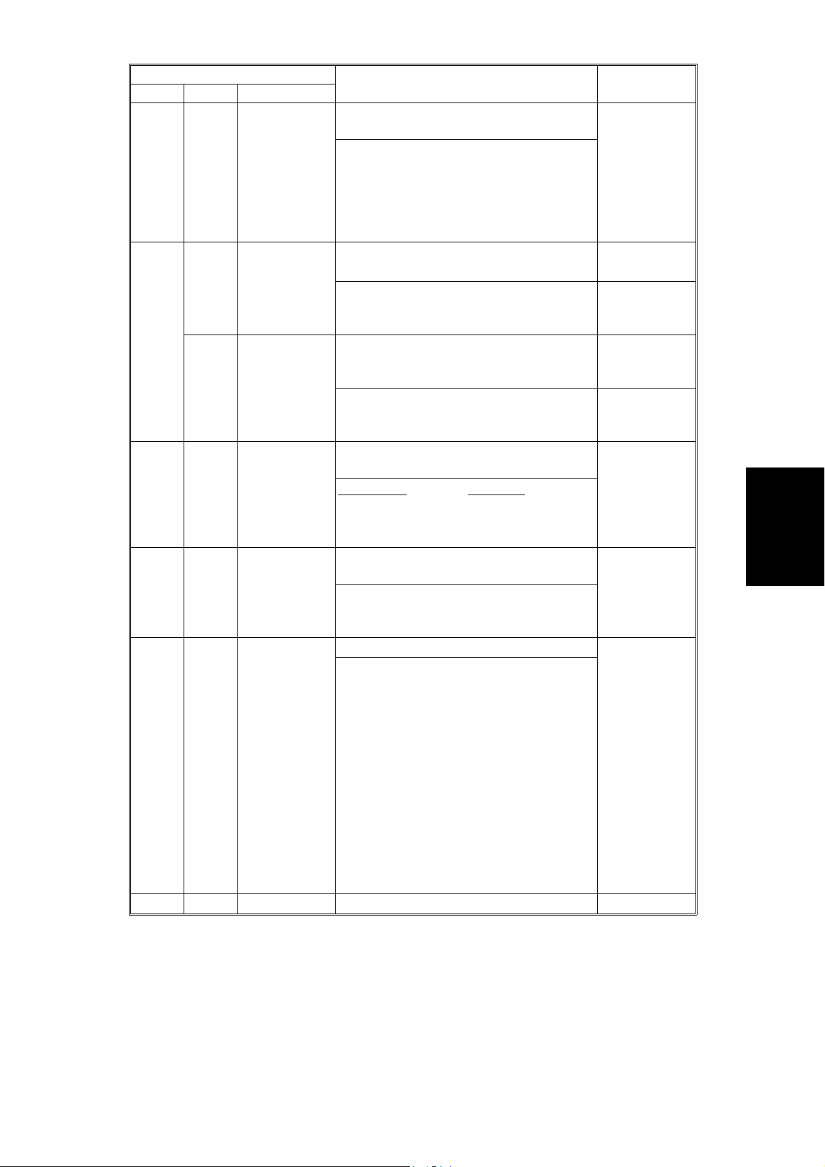
Mode No.
Class 1 Class 2
2207 Forced Toner
Supply
Forces the toner bottle to supply toner to
the toner supply unit for 30 seconds.
Function Settings
Toner supply finishes automatically after
30 seconds. This process is not normally
needed in the field for this model. At
installation, doing the 50-page free run
also supplies toner to the development
unit.
2208 * 1 * Toner Supply
Mode
Selects the toner supply mode.
Use fixed supply mode only as a
temporary measure if process control is
not working.
2 * Toner Supply
Ratio
(Fixed Supply
Mode)
Selects the toner supply ratio for Fixed
Supply Mode.
Use a higher value if the user tends to
make lots of copies that have a high
proportion of black.
2209 * Toner Supply
Rate
(Detect
Supply Mode)
Adjusts the toner supply rate for Detect
Supply Mode.
ncreasing this value reduces the toner
I
supply clutch on time. Use a lower value
if the user tends to make lots of copies
that have a high proportion of black.
2210 * ID Detection
Interval
Changes the interval for making the ID
sensor pattern (V
SP/VSG
detection).
Reducing the interval will also reduce the
CPM.
Do not adjust this.
2220 * V
TREF
Setting
Manual
Adjust the V
of the TD sensor. 1.50 ~ 3.00
TREF
Change this value after replacing the
development unit with another one that
already contains toner.
For example, when using a development
unit from another machine for test
purposes, do the following:
1. Check the value of SP2220 in both the
machine containing the test unit and the
machine that you are going to move it to.
2. Install the test development unit, then
input the V
for this unit into SP2220.
TREF
3. After the test, put back the old
development unit, and change SP2220
back to the original value.
2223 * VT Display Displays the TD sensor output voltage.
Detect
Fixed
6%
15%
30%
50 ~ 200
1 mg/s / step
116 mg/s
10 ~ 200
1 copy/step
200 copies
0.01V/step
2.52V
Tables
Service
FSM 4-11 A133/A217
Page 76

Mode No.
Class 1 Class 2
2301 * 1 * Transfer
Current
Adjustment
(1st side of
the paper)
2 * Transfer
Current
Adjustment
(2nd side of
the paper)
6 * Transfer
Current
Adjustment
(By-pass
Feed)
2801 TD Sensor
Initial Setting
2803 Forced
Charge
Corona Wire
Cleaning
2804 * 1 * Charge
Corona Wire
Cleaning
Enable/Disable
2 * Charge
Corona Wire
Cleaning
Interval
Function Settings
Adjusts the current applied to the transfer
belt during copying on the 1st side of the
paper.
If the user uses thicker paper, the current
may have to be increased to ensure
sufficient transfer of toner.
Adjusts the current applied to the transfer
belt during copying on the 2nd side of the
paper.
See above
Adjusts the current applied to the transfer
belt during copying from the by-pass feed
table.
.
See above; note that thicker paper can
be fed from the bypass feed tray, so the
factory setting is higher.
Performs the TD sensor initial setting.
This SP mode controls the voltage
applied to the TD sensor to make the TD
sensor output about 2.5 V.
Use this mode only after installing the
machine, changing the TD sensor, or the
adding new developer. This mode cannot
be run until the machine has reached the
Ready condition.
Forces the charge corona wire cleaning
motor to start cleaning.
This only works if the optional wire
cleaning motor is installed.
Determines whether to clean the charge
corona wire every time interval set with
SP 2804-2.
This only works if the optional wire
cleaning motor is installed.
Changes the interval for charge corona
wire cleaning.
This only works if the optional wire
cleaning motor is installed.
10 ~ 60
1 µA/step
32 µA
10 ~ 60
1 µA/step
32 µA
10 ~ 60
1 µA/step
48 µA
100 ~ 10000
100
copies/step
2500 copies
A133/A217 4-12 FSM
Page 77

Rev. 12/3/96
Mode No.
Class 1 Class 2
2902 1 Test Pattern
Printing
(Analog Video
Processing)
2 Test Pattern
Printing
(Digital Video
Processing)
3 Test Pattern
Printing
(Printing)
6 Not Used.
Function Settings
Prints the test patterns for analog video processing.
See section 2.2.2 for how to print test patterns.
0. Not used 1. 16 gradations
2. 128-dot intervals 3. 64-dot intervals
This SP mode is useful for finding whether the SBU or
EX-IPU failed. If the printout is OK, the SBU is defective.
If the printout is not OK, the EX-IPU is defective.
Prints the test patterns for digital video processing.
See section 2.2.2 for how to print test patterns.
0. Not used 1. Vertical Stripes 2. Grayscales
3. Cross Pattern 4. Black Bands
This SP mode is useful for finding whether the printer or
the EX-IPU failed. If the printout is OK, the EX-IPU is
defective. If the printout is not OK, the printer is defective.
Prints the printer test patterns.
See section 2.2.2 for how to print test patterns.
Example: 10. Trimming Area
For the other test patterns, refer to section 2.2.2.
This SP mode is useful for finding the part that failed. If
the printout is OK, the EX-IPU is defective. If the printout
is not OK, the printer is defective.
Do not change this value
2905 * LD PWM
Laser Pulse
Positioning
2906 * TD Sensor
Input Voltage
2909 * Main Scan
Magnification
2950 * Side-to-Side
Registration
(Base)
3001 ID Sensor
Initial Setting
Selects the laser pulse positioning type
that is used for test printouts and when in
binary picture processing mode.
If SP 4904-1 is set to NO, this SP mode
is ignored. The "center" setting will be
2: Center
3. Left
4. Right
5.
Concentrated
used.
Use to input the TD sensor control
voltage.
Factory use only
Adjusts the magnification in the main
scan direction for the printer.
Use the
•/∗
key to toggle between + and
4 ~ 10
0.1 V/step
8.0 V
- 2.54 ~ + 2.54
0.02 %/step
+ 0.00 %
-. See "Replacement and Adjustment Copy Image Adjustments" for details.
Changes the printing start position. - 12.7 ~ + 12.7
Factory use only
Performs the ID sensor initial setting. The
ID sensor output for the bare area of the
drum (V
) is adjusted to 4.0 ± 0.2V.
SG
0.1 mm/step
+ 0.0 mm
This SP mode should be performed after
replacing or cleaning the ID sensor or
replacing the drum.
Tables
Service
FSM 4-13 A133/A217
Page 78

Rev. 12/3/96
Mode No.
Class 1 Class 2
3103 * ID Sensor
Output
Display
4008 * Sub Scan
Magnification
(Scanning)
4010 * Leading Edge
Registration
(Scanning)
4011 * Side-to Side
Registration
(Scanning)
4012 * 1 * Leading Edge
Erase Margin
(Scanning)
2 * Trailing Edge
Erase Margin
(Scanning)
3 * Left Side
Erase Margin
(Scanning)
4 * Right Side
Erase Margin
(Scanning)
4013 Scanner Free
Run
Function Settings
Displays the current V
If the ID sensor does not detect the ID
pattern, "V
SP
=5.0v/V
and VSP output. VSP=x.xxV
SG
V
=5.0v" is
SG
SG
=x.xxV
displayed.
If the ID sensor does not detect the bare
area of the drum, "V
=0.0v/VSG=0.0v" is
SP
displayed.
Adjusts the magnification in the sub scan
direction for scanning.
If this value is changed, the scanner
- 9.0 ~ + 9.0
0.1 %/step
+ 0.0 %
motor speed is changed.
Use the
•/∗
key to toggle between + and
-. See "Replacement and Adjustment Copy Image Adjustments" for details.
Adjusts the leading edge registration for
scanning.
(-): the image moves in the direction of
- 9.0 ~ + 9.0
0.1 mm/step
+ 0.0 mm
the leading edge
•/∗
Use the
key to toggle between + and
-. See "Replacement and Adjustment Copy Image Adjustments" for details.
Adjusts the side-to-side registration for
scanning.
(-): the image disappears at the left side.
- 6 ~ + 6
0.1 mm/step
+ 0.0 mm
(+): The image appears.
•/∗
Use the
key to toggle between + and
-. See "Replacement and Adjustment Copy Image Adjustments" for details.
Adjusts the leading edge margin for
scanning.
Do not adjust this unless the user wishes
0.0 ~ +9
0.1 mm/step
1.0 mm
to have a scanner margin that is greater
than the printer margin.
Adjusts the trailing edge margin for
scanning.
See the comment for SP 4012-1.
0.0 ~ 9
0.1 mm/step
0.5 mm
Adjusts the left side margin for scanning. 0.0 ~ 9
See the comment for SP 4012-1.
0.1 mm/step
1.0 mm
Adjusts the right side margin for
scanning.
See the comment for SP 4012-1.
0.0 ~ 9
0.1 mm/step
0.5 mm
Performs a scanner free run with the
exposure lamp off.
A133/A217 4-14 FSM
Page 79

Mode No.
Class 1 Class 2
4301 APS Sensor
Output Display
4303 * APS Small
Size Original
Detection
4428 Standard
White Level
Adjustment
4901 * 2 * GA 1 Setting
(GAIN 0)
5 * GA 1 Setting
(GAIN 1)
8 * GA 1 Setting
(REF)
11 * GA 1 Setting
(Video Data
Path)
Function Settings
Displays the size of an original placed on
the exposure glass.
If A5 or 5
1/2
" x 8
" is displayed, check
1/2
the current setting of SP 4303;
depending on that SP mode setting, A5
or 5
1/2
" x 8
" may be displayed if the
1/2
APS sensors cannot detect the paper
size.
Selects whether or not the copier
determines that the original is A5/HLT
size when the APS sensor does not
Not detected
A5 length /
"X8
5
1/2
1/2
detect the size.
If "A5 length / 5
1/2
" x 8
"" is selected,
1/2
paper sizes that cannot be detected by
the APS sensors are regarded as A5
lengthwise or 5
1/2
" x 8
1/2
".
If "Not detected" is selected, "Cannot
detect original size" will be displayed.
Corrects the standard white level of the
white plate.
This SP mode is for factory use only.
Do not change the value
The coefficient of the D/A converter for
the standard AGC gain curve.
This SP mode is for factory use only.
Do not change the value
The coefficient of the D/A converter for
the AGC gain curve at power on.
This SP mode is for factory use only.
Do not change the value
The coefficient of the D/A converter for
the AGC gain curve for scanning the
white plate.
.
0 ~ 255
1 /step
100
.
0 ~ 255
1 /step
100
.
0 ~ 255
1 /step
100
This SP mode is for factory use only.
Do not change the value
.
Selects one of the following video data outputs, which will
be used for printing.
0. After GA1 functions
1. Before auto shading processing
2. After black auto shading processing
3. After all auto shading processing (black and white)
Do not change the value.
Tables
Service
FSM 4-15 A133/A217
Page 80

Mode No.
Class 1 Class 2
4903 * 1 * GA 3 Setting
(Filter Level)
Function Settings
Selects the strengths of the MTF and
smoothing filters.
bit 7, 6: Letter Mode (MTF)
00: Normal 01: Weak 10: Weaker
11: Weakest
bit 5, 4: Generation Mode (MTF)
00: Normal 01: Weak 10: Weaker
11: Weakest
bit 3: Not used
Keep at "0"
bit 2: Letter/Photo Mode (Smoothing)
0: Sharp 1: Smooth
bit 1: Photo Mode (MTF)
0: Weak 1: Strong
bit 0: Photo Mode (Smoothing)
0: Smooth 1: Sharp
Input the setting for all 8 bits at once as a
decimal value.
(e.g. To set the MTF filter strength of the
the generation mode to ’weak’, the input
value should be 16 as shown below,
assuming all other parameters are at the
’zero’ setting.
→
00010000
16
0 ~ 255
0
2 * GA 3 Setting
(Filter Mode)
3 Not used
4 * GA 3 Setting
(White
Threshold)
5 GA3 Setting
(Full Size)
6 GA 3 Setting
(Test Pattern
Output)
The type of filter used in Photo mode
depends on the setting of SP4904-3.
Selects the coefficients and strengths of
the MTF filter and smoothing filter.
Do not change the value.
Changes the threshold level for dot
screen detection processing.
Do not change the value.
Selects whether the copy image is
always in the full size mode even if the
magnification ratio has been changed.
This SP mode is used for checking the
0 ~ 16
1 /step
3
0 ~ 255
1 /step
80
0: Normal
Operation
1: Always full
size mode
magnification function in the main scan
direction, which is performed by the GA3
chip.
Prints the test pattern for the GA3 or selects one of the
following video data outputs for printing.
0. Normal
1. Test pattern print out
2. Skips the magnification processing.
3. Skips the filter processing
4. Skips the GA3 functions
This SP mode is used for checking the GA3 functions.
A133/A217 4-16 FSM
Page 81

Mode No.
Class 1 Class 2
4903 7 * GA 3 Setting
(Main Shift
High)
8 * GA 3 Setting
(Main Shift
Low)
9 * GA 3 Setting
(Switch
Separation)
4904 * 1 * GA4 Setting
(Laser Pulse
Positioning)
2 * GA4 Setting
(Photo Matrix)
3 * GA4 Setting
(Filter Select
in Photo
Mode )
4 * GA4 Setting
(Binary
Process
Mode)
6 GA4 Setting
(Generation
Mode)
7 GA4 Setting
(Image
Process mode
in Letter/
Photo mode:
Letter areas)
Function Settings
Changes the image shift amount for the
main scan direction in magnification
mode.
0 ~ 255
1 /step
0
Do not change the values of 4903-7
and 4903-8.
Changes the threshold ratio for auto
text/photo separation processing.
This is used only in the Japanese model.
Selects whether LD PWM laser pulse
positioning feature is performed or not.
25 ~ 255
1 %/step
170 %
0: OFF
1: ON
If "No" is selected, the copier always
uses the "center" setting (pixels will
always have a small separation).
Selects the matrix size for photo mode. 0: 4 x 4
• 8 x 8 is only used if 4904-4 is set to
"binary". Also, if 4904-4 is set to binary,
4904-2 will be ignored if the setting is
1: 6 x 6
2: 8 x 8
3: 6 x 6 (New)
other than 8 x 8.
•
6 x 6 (New) should be selected when a
light original is used.
•
4 x 4 leads to a sharper image
Selects either the MTF filter or the
smoothing filter in Photo mode.
The strength of the MTF filter can be
0: MTF filter
1: Smoothing
filter
selected with SP4903-1, bit 1.
The strength of the Smoothing filter can
be selected with SP4903-1, bit 0.
If you select the MTF filter, the image
resolution is improved. However, the dot
screen areas will be faint.
Selects whether binary picture
processing mode is performed or not.
0: NO
1: YES
If YES is selected, all image processing
modes are handled using binary picture
processing mode.
Selects the line width correction type in
the generation mode.
In generation mode, lines may bulge in
the main scan direction. Adjust this SP
mode until the result is satisfactory.
Selects the image processing mode used for Letter areas
in Letter/Photo mode.
0: 1 x 1 dot processing
1: Error diffusion with 1 x 1 dot processing
2: 2 x 1 dot processing
3: Error diffusion with 2 x 1 dot processing
0: Not
corrected
1: Thin line-1
2: Thin line-2
3: Thick line
A larger value cases the image to became lighter.
Only works if 4904-4 is at 0.
Tables
Service
FSM 4-17 A133/A217
Page 82

Mode No.
Class 1 Class 2
4904 8 GA4 Setting
(Image
Process mode
in
Letter/Photo
mode: Photo
Areas)
10 GA4 Setting
(GA4 Test
Data)
12 * GA4 Setting
(BK Thresh
Level)
13 * GA4 Setting
(Top point
Level)
14 * GA4 Setting
(All Black
Level)
16 * GA4 Setting
(Print Top
Point Level)
17 * GA4 Setting
(Print All
Black Level)
18 * GA4 Setting
(Dither
Pattern)
4905 1 Path Setting
(ASAP Video
2
In)
4907 GA4 Setting
(Auto
letter/photo
separation)
Function Settings
Selects the image processing mode used for photo areas
in the Letter/Photo mode.
0: 1 x 1 dot processing
1: Error diffusion with 1 x 1 dot processing
2: 2 x 1 dot processing
3: Error diffusion with 2 x 1 dot processing
A smaller value causes the image to become more sharp
in focus.
Only works if 4904-4 is at 0.
Prints the test pattern for the GA4 IC, to test the GA4 chip
on the EX-IPU.
0: No Print
1: Gradation
2: Cross
3: Black bands
Changes the threshold level for binary
picture processing mode.
A larger value causes the image to
0 ~ 255
1 /step
40
become lighter.
The value for pixels at an edge in binary
picture processing mode.
Do not change the value.
The value for black areas in binary
picture processing mode.
Do not change the value.
The value for pixels at an edge in stamp
mode.
Do not change the value.
The value for black areas in stamp mode. 0 ~ 255
Do not change the value.
Selects the dither pattern used in binary
picture processing mode.
Do not change the value
.
These SP modes are used for design
0 ~ 255
1 /step
128
0 ~ 255
1 /step
255
0 ~ 255
1 /step
128
1 /step
255
0: 70-line
1: 95-line
2: 140-line
3: 180-line
0
purposes only.
Do not change the settings.
Selects whether the auto letter/photo
separation is performed in the
Letter/Photo mode or not.
Disabled
Enabled
Test purposes only
A133/A217 4-18 FSM
Page 83

Mode No.
Class 1 Class 2
4909 1 GA4 Setting
(Pulse Width
Modulation)
2 GA4 Setting
(Line Width
Correction 1 :
White
3 GA4 Setting
(Line Width
Correction 1 :
Black
4 GA4 Setting
(Line Width
Correction 2 :
White
5 GA4 Setting
(Line Width
Correction 2 :
Black
6 GA4 Setting
(Error
Diffusion
Gamma)
7 GA4 Setting
(Edge
Detection 1)
8 GA4 Setting
(Edge
Detection 2)
17 GA4 Setting
(Background
Pattern Merge
Method)
Function Settings
Decides the threshold level for selecting
the type of pulse width modulation that is
used.
Do not change the value.
Decides the threshold value for a pixel to
be white when line width correction type
1 is performed.
Do not change the value.
Decides the threshold value for a pixel to
be black when line width correction type
1 is performed.
Do not change the value.
Decides the threshold value for a pixel to
be white when line width correction type
2 is performed.
Do not change the value.
Decides the threshold value for a pixel to
be black when line width correction type
2 is performed.
Do not change the value.
Selects the gamma type for error
diffusion.
Do not change the value.
Decides the threshold value to calculate
the difference value between the object
pixel and the surrounding pixels.
Do not change the value.
Decides the threshold value for detecting
the edge area.
Do not change the value.
Selects whether an image which
overlaps a background numbering
pattern is converted from positive to
negative or not.
This SP mode is used when a
background numbering pattern is
overlapping a solid black area.
0 ~ 255
1 /step
0
0 ~ 255
1 /step
0
0 ~ 255
1 /step
0
0 ~ 255
1 /step
0
0 ~ 255
1 /step
0
0 ~ 7
1 /step
0
0 ~ 255
1 /step
0
0 ~ 255
1 /step
0
0: Not
converted
1: Converted
Tables
Service
FSM 4-19 A133/A217
Page 84

Mode No.
Class 1 Class 2
4909 18 GA4 Setting
(Stamp
Pattern Merge
Method)
19 GA4 Setting
(Data Path
Selection 1)
20 GA4 Setting
(Data Path
Selection 2)
4911 1 HDD Setting
(Media Test)
2 HDD Setting
(Formatting)
3 HDD Setting
(Spindle
Control)
4 HDD Setting
(Head
Retraction)
Function Settings
Selects whether an image which overlaps
a stamp pattern is converted from
positive to negative or not.
The settings 0 and 1 are the same as for
4909-17 above. The setting 2 means that
the black level of the stamp (SP4904-17)
is inverted (e.g. when the black level of
the stamp is 200, the stamp pattern is
printed at black level 55.)
This SP mode is used when a stamp
pattern is overlapping a solid black area.
These SP modes are used for design
purposes only.
Do not change the settings.
These SP modes are used for design
purposes only.
Do not change the settings.
Checks for bad sectors on the hard disk
that develop during machine use. This
takes 4 minutes.
This SP mode should be done when an
abnormal image is printed. There is no
need to do this at installation as the hard
disk firmware already contains bad sector
information, and damage is not likely
during transportation.
Bad sectors detected with this SP mode
will be stored in the E
2
PROM on the
EX-IPU board with the bad sector data
copied across from the firmware.
Formats the hard disk. This takes 10
seconds.
Decides the disk drive motor (spindle
motor) stop timing.
Yes: The hard disk stops in low power
mode. The first copy after returning to
standby will take longer.
No: The hard disk keeps going in low
power mode
Press Enter to move the head of the hard
disk away from the disk while the disk is
turning. The head automatically moves
back when a copy is made.
This SP should be performed when the
machine will be moved without turning
the main switch off.
0: Not
converted
1: Converted
2: Inverted
0
0
A133/A217 4-20 FSM
Page 85

Rev. 5/97
Mode No.
Class 1 Class 2
4911 5 HDD Setting
(Total Storage
Capacity)
Input the total storage capacity of the
hard disk at replacement.
In future, hard disks of various sizes may
Function Settings
be available. In this case, use this SP
mode when installing a new disk.
6 HDD Setting
(Bad Sector
Information
Reset)
Resets the bad sector information which
is stored in the E
2
PROM on the EX-IPU
board.
This SP should be performed when the
hard disk is replaced.
7 HDD Setting
(Bad Sector
Displays the number of bad sectors there
are on the hard disk.
Display)
5019 LCT Paper
Size Setting
Selects the paper size for the LCT. A4 (230V
When changing the setting, the position
of the side fences for the LCT should be
changed.
5104 * A3/11"x17"
Double Count
Specifies whether the counter is doubled
for A3/11"x17" paper.
If "YES" is selected, the total counter and
the current user code counter counts up
twice when A3/11"x17" paper is used.
5106 * ADS Level
Selection
5118 * Disable
Copying
5220 * Auto Stamp
Function
5305 Auto Off Mode
Selects the image density level that is
used in ADS mode.
Selects whether the copy function is
disabled or not.
Selects whether the auto stamp function
is enabled or not.
This SP mode is used only for 115V
machines (Energy Star
standardization).
Selects whether the auto off timer setting
is enabled or disabled
When "disabled" is selected, the auto off
timer range will be wider than the default
timer range. (In UP mode, the user will
be able to select a time between 0 and
120 minutes.) If "0" is selected, the auto
off timer function is disabled
.
5501 * 1 PM Alarm Selects whether the PM alarm is enabled
or not.
5501 2 PM Alarm
Interval
Sets the PM interval, with an alarm. 0 ~ 255
When the setting is "0", this function is
disabled.
machines)
X 11
8
1/2
(115V
machines)
No
Yes
1 ~ 7
1 notch /step
4
No
Yes
On (115V
machine)
Off (230V
machine)
Enabled
Disabled
Enabled
Disabled
1k copies/step
120 k copies
Tables
Service
FSM 4-21 A133/A217
Page 86

Mode No.
Class 1 Class 2
5801 Memory All
Clear
Resets all correction data for process
control and all software counters. Also,
returns all modes and adjustments to the
default settings.
See the "MEMORY ALL CLEAR" section
for how to use this SP mode correctly.
Function Settings
Normally, this SP mode should not be
used.
It is used only after replacing the
NVRAM, or when the copier malfunctions
due to a damaged NVRAM.
5802 Free Run Performs a free run. The scanner scans
once and the printer prints for the number
of copies requested.(Press "Copy Mode",
then "Start")
5803 1 ~ 9 Input Check Displays the signals received from
sensors and switches.
See the "INPUT CHECK" section for
details.
5804 Output Check Turns on the electrical components
individually for test purposes.
See the "OUTPUT CHECK" section for
details.
5807 Option
Connection
Check
5811 * Machine
Serial Number
Checks the connectors to the options.
Use to input the machine serial number.
This serial number will be printed on the
system parameter list.
5812 * Service
Telephone
Number
Use this to input the telephone number of
the service representative (this is
displayed when a service call condition
occurs.)
Press the "•/#" key to input a pause ().
Press the "Clear modes" key to delete
the telephone number.
5902 Duplex Tray
Capacity Limit
for A3 Copies
Selects the total capacity of the duplex
tray for A3 (11 x 17") paper.
50 sheets
30 sheets
If there are frequent jams at the duplex
unit when using A3 paper, try setting this
to 30.
A133/A217 4-22 FSM
Page 87

Mode No.
Class 1 Class 2
5920 * Fusing Temp.
Setting - Low
Power Mode
5990 1 SP Mode
Data Printing
(All Data)
2 SP Mode
Data Printing
(SP Mode
Data)
3 SP Mode
Data Printing
(UP Mode
Data)
4 SP Mode
Data Printing
(Machine
Status Data)
6006 * 1 * ADF Side-to
Side
Registration
2 * ADF Leading
Edge
Registration
(Simplex)
3 * ADF Leading
Edge
Registration
(Duplex-front)
4 * ADF Leading
Edge
Registration
(Duplex-rear)
For details on the correct way to use SP 6006, see the ADF service manual.
Function Settings
Selects the fusing temperature that will
be used in low power mode.
If a low temperature is selected, it takes
(115V ver.)
125 °C
100 °C
more time to reach the ready condition.
(230V ver.)
170 °C
155 °C
125 °C
100 °C
Prints all the system parameter lists.
See the "SYSTEM PARAMETER AND
DATA LISTS" section for how to print the
lists.
Printing takes 6 minutes.
Prints the SP mode data list.
See the "SYSTEM PARAMETER AND
DATA LISTS" section for how to print the
lists.
Printing takes 2 minutes.
Prints the UP mode data list.
See the "SYSTEM PARAMETER AND
DATA LISTS" section for how to print the
lists.
Printing takes 2 minutes.
Prints the machine status history data list.
See the "SYSTEM PARAMETER AND
DATA LISTS" section for how to print the
lists.
Printing takes 2 minutes.
Adjusts the printing side-to-side
registration in the ADF mode.
Use the
•/∗
key to toggle between + and
-3 ~ +3
0.1 mm/step
+ 0.0 mm
-.
Adjusts the original stop position. -3 ~ +3
Use the
•/∗
key to toggle between + and
-.
Adjusts the original stop position against
the original left scale in one-sided original
mode.
Use the
•/∗
key to toggle between + and
0.1 mm/step
+ 0.0 mm
-3 ~ +3
0.1 mm/step
+ 0.0 mm
-.
Adjusts the original stop position against
the original left scale in two-sided original
mode.
Use the
•/∗
key to toggle between + and
-3 ~ +3
0.1 mm/step
+ 0.0 mm
-.
Tables
Service
FSM 4-23 A133/A217
Page 88

Rev. 12/3/96
Class 1 Class 2
6009 ADF Free Run Performs an ADF free run.
6105 * Finisher
6107 Finisher Free
⇒
7004 Japanese version only. Do not change
7804 PM Counter
7807 SC/Jam
7808 Resets
Mode No.
Staple
Position
Adjustment
Run
Reset
Counter Reset
Counters
(except for the
total counter)
Function Settings
This is a general free run controlled from
the copier. For more detailed free run
modes, see the DF manual.
Adjusts the staple position when using
the finisher.
Use the
One staple position: A larger value
causes the staple position to shift inward.
Two staple position: A larger value
causes both staple positions to shift to
the rear side of the machine.
Performs a finisher free run (without
stapler).
This is a general free run controlled from
the copier. For more detailed free run
modes, see the finisher manual.
this value.
Resets the PM counter. To see the
Resets the SC and jam counters.
Resets the following counters:
On the data list, between "Total No of
Org from ADF" and "Number of SCs:
Others", and between "Counter from
ADF" and "Staple Mode".
•/∗
key to toggle between + and -.
- 1~ +3.5
0.5 mm/step
+0.0 mm
current
counter
values, print
the SP mode
data lists (SP
5990).
7810 User Code
Number Reset
Resets the user code numbers.
A133/A217 4-24 FSM
Page 89

Mode No.
Class 1 Class 2
7901 1 ROM/CPU
Version
(Operation
Panel)
2ROM/CPU
Version
(MSIS)
3ROM/CPU
Version
(Copy App.)
4ROM/CPU
Version
(BCU:68340)
5ROM/CPU
Version
(AC Power
Control)
6ROM/CPU
Version
(High Voltage)
7ROM/CPU
Version
(EX-IPU)
8ROM/CPU
Version
(ADF)
9ROM/CPU
Version
(Paper Feed
Unit)
7901 10 ROM/CPU
Version
(Sorter/
Finisher)
11 ROM/CPU
Version
(MSU)
Function Settings
Displays the operation panel board ROM
version.
Displays the ROM version for the MSIS
on the SCU board.
Displays the ROM version for the copy
application on the SCU board.
Displays the CPU version for the fusing
controller on the BCU board.
Displays the ROM version for AC power
control on the AC drive board.
Displays the ROM version for the high
voltage control board.
Displays the ROM version for the EX-IPU
board.
Displays the ROM version for the ADF.
Displays the ROM version for the paper
feed unit.
Displays the ROM version for the
sorter/finisher.
Displays the ROM version for the
memory unit on the EX-IPU board.
Tables
Service
FSM 4-25 A133/A217
Page 90

2.2.2 TEST PATTERN PRINTING (SP 2902 )
1. Access the SP mode which holds the test pattern that you need.
2. Touch the "Copy Mode" button on the display to access the copy mode
display.
3. Select the required copy features such as paper size, image density,
reduction.
4. Press the "Start" key on the operation panel.
5. After checking the test patte r n, le ave copy mod e by to uch i ng the "SP
Mode" button on the display.
6. Touch the "Quit" button to leave the SP mode.
CAUTION
+
Before leaving the SP mode, return the setting of the SP mode to 0
(No Print). Otherwise, the user will get a test pattern whenever taking
a copy.
Test Pattern Table for SP2902-3
No. Test Pattern No. Test Pattern
0 No Print 16 32 Grayscales (Horizontal)
1 Vertical Lines (1 dot) 17 32 Grayscales (Vertical)
2 Horizontal Lines (1 dot) 18 32 Grayscales (Vert./Hor.)
3 Vertical Lines (2 dots) 19 32 Grayscales (V/H Overlay)
4 Horizontal Lines (2 dots) 20 64 Grayscales (Horizontal)
5 Grid Pattern (single dot) 21 64 Grayscales (Vertical)
6 Grid Pattern (double dots) 22 64 Grayscales (Vert./Hor.)
7 Alternating Dot Pattern 23 64 Grayscales (V/H Overlay)
8 Full Dot Pattern 24 128 Grayscales (Horizontal)
9 Black Band 25 128 Grayscales (Vertical)
10 Trimming Area 26 128 Grayscales (Vert./Hor.)
11 Argyle Pattern 27 128 Grayscales (Vert./Hor. Overlay)
12 16 Grayscales (Horizontal) 28 256 Grayscales (Horizontal)
13 16 Grayscales (Vertical) 29 256 Grayscales (Vertical)
14 16 Grayscales (Vert./Hor.) 30 256 Grayscales (Vert./Hor.)
15 16 Grayscales (Vert./Hor. Overlay) 31 256 Grayscales (Vert./Hor. Overlay)
A133/A217 4-26 FSM
Page 91
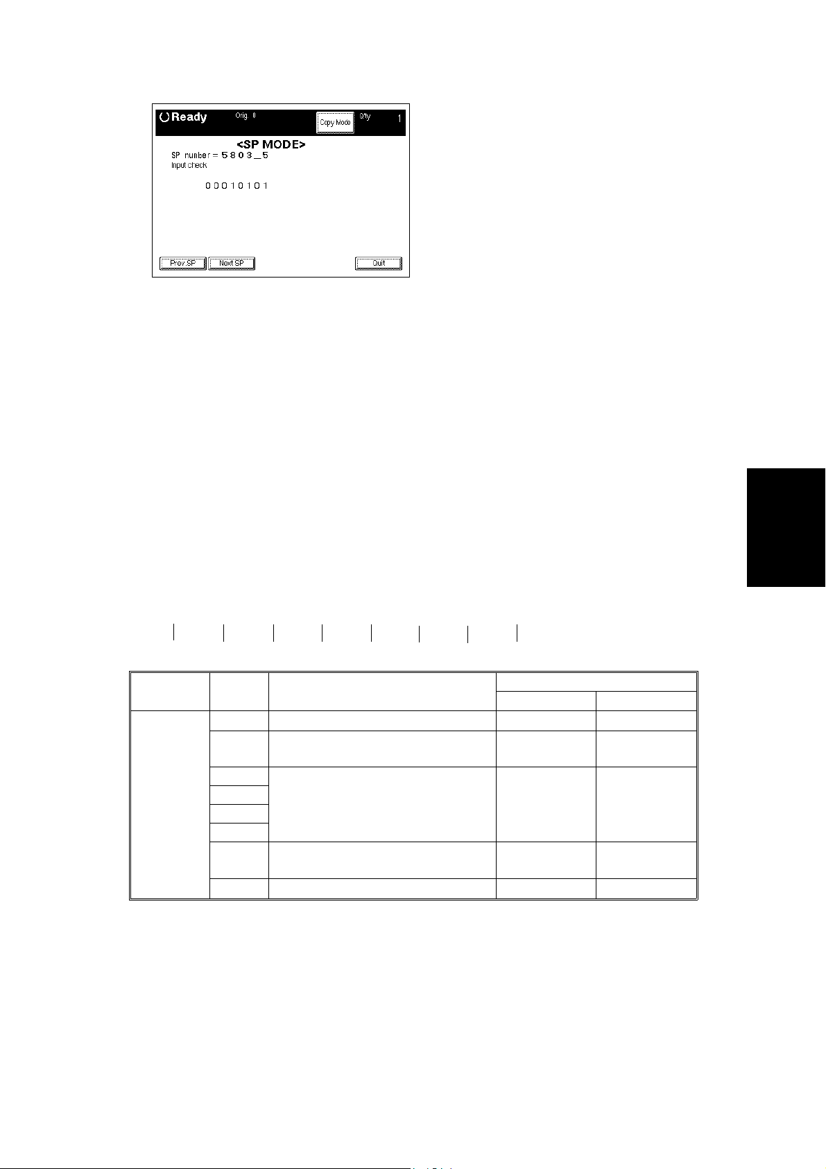
2.2.3 INPUT CHECK (SP5803)
Rev. 6/96
1. Access SP mode 5803.
2. Select the class 2 SP number which will access the switch or sensor you
wish to check (see the table that follows this procedure).
3. Check the status of the sensor or sw itch .
NOTE:
If you wish to change to another class 2 level, touch "Next SP"
or "Prev. SP" on the display.
4. If you wish to check the signal during a copy cycle, enter copy mode
from the SP mode, select the required copy modes, then press the Start
key. After that, go back to the SP mode to check the signal.
5. The reading ("0" or "1") will be displayed. The meaning of the display is
as follows.
bit7 bit6 bit5 bit4 bit3 bit2 bit1 bit0
0 0 0 0 0 0 0 0
Class 2
no.
1 7 Not used
bit no. Description
6 LCT Paper End Sensor Paper not
5 Not used
4
3
2
1 Registration Sensor Paper not
0 Not used
detected
detected
Reading
01
Paper
detected
Paper
detected
Tables
Service
FSM 4-27 A133/A217
Page 92

Class 2
no.
2 7 Not used
3 7 Thermistor Normal Overheat
4 7 Not used
5 7 DIP Switch 8 (BCU) Not used
bit no. Description
6 LCT Switch LCT unit
closed
5 Front Cover Safety Switch Front cover
closed
4 Relay Sensor 3 (Option PFU) Paper not
detected
3 Relay Sensor 2 (Option PFU) Paper not
detected
2 Relay Sensor 1 (Option PFU) Paper not
detected
1 By-pass Feed Paper End Sensor Paper
detected
0 By-pass Feed Table Switch By-pass feed
table closed
6 Not used
5 Toner End Sensor No toner Toner present
4 Toner Overflow Sensor Bottle not full Bottle full
3 Not used
2 Transfer Belt Position Sensor Transfer belt
down
1 Not used
0
6
5 LCT Tray Down Switch Switch not
pressed
4 LCT Lower Limit Sensor Bottom plate
not at lower
position
3 LCT Upper Limit Sensor Paper not at
high position
2 LCT Set Signal Not connected Connected
1 LCT Cover Sensor LCT cover
closed
0 LCT/By-pass Relay Sensor Paper not
detected
6 DIP Switch 7 (BCU) Not used
5 DIP Switch 6 (BCU) Version Setting (see Table 1)
4 DIP Switch 5 (BCU) Version Setting (see Table 1)
3 DIP Switch 4 (BCU) SC is enabled SC is disabled
2 DIP Switch 3 (BCU) No duplex Duplex
1 DIP Switch 2 (BCU) Black Twin Color
0 DIP Switch 1 (BCU) 25 CPM 40 CPM
Reading
01
LCT unit open
Front cover
open
Paper
detected
Paper
detected
Paper
detected
Paper not
detected
By-pass feed
table open
Transfer belt
up
Switch pressed
Bottom plate
at lower
position
Paper at high
position
LCT cover
open
Paper detected
A133/A217 4-28 FSM
Page 93

Class 2
no.
6 7 Print start signal Not activated Activated
7 7 Not Used
bit no. Description
6 Main Motor Lock signal Not detected Detected
5 Ozone Fan Motor Lock signal Not detected Detected
4 Exhaust Fan Motor Lock signal Not detected Detected
3 By-pass Feed Table Paper Width
Data
2
1
0
See Table 2
Reading
01
6 Upper Relay Sensor Paper not
detected
5 Not Used
4
3
2
1
0
8 7 Paper End Sensor Paper
detected
6 Lower Relay Sensor Paper not
detected
5 Tray Upper Limit Sensor Paper not at
high position
4 Tray Paper Size Sensor - 5 Switch not
pressed
3 Tray Paper Size Sensor - 4 Switch not
pressed
2 Tray Paper Size Sensor - 3 Switch not
pressed
1 Tray Paper Size Sensor - 2 Switch not
pressed
0 Tray Paper Size Sensor - 1 Switch not
pressed
9 7 Duplex Unit Set Signal Not detected Detected
6 Fusing Unit Set Signal Not detected Detected
5 Fusing Exit Sensor Paper not
detected
4 Duplex End Fence H.P Sensor End fence not
at home
position
3 Duplex Side Fence H.P Sensor Side fence not
at home
position
2 Duplex Turn Sensor Paper not
detected
1 Duplex Entrance Sensor Paper not
detected
0 Duplex Paper End Sensor Paper not
detected
Paper detected
Paper not
detected
Paper
detected
Paper at high
position
Switch pressed
Switch pressed
Switch pressed
Switch pressed
Switch pressed
Paper
detected
End fence at
home position
Side fence at
home position
Paper detected
Paper detected
Paper detected
Tables
Service
FSM 4-29 A133/A217
Page 94

Table 1: Version Setting
Class 2
no.
5 0 0 Japanese version
Bit 4 Bit 5 Version
1 0 120V version
0 1 230V version
1 1 Not used
Table 2: By-pass Feed Table Paper Size Data
Class 2
no.
60000Post Card
Bit 3 Bit 2 Bit 1 Bit 0 Paper Width
0 0 0 1 B6 Lengthwise
0 0 1 0 B5 Lengthwise
0 0 1 1 A5 Lengthwise / 5
0 1 0 0 B4 Lengthwise
0 1 1 0 A4 Lengthwise / 8
1 0 0 0 A3 Lengthwise
1 1 0 0 11" x 17"
1/2
1/2
"
" / 8"
1: Contact closed
A133/A217 4-30 FSM
Page 95

2.2.4 OUTPUT CHECK (SP5804)
CAUTION
+
Motors keep turning in this mode regardless of upper or lower limit
sensor signals. To prevent mechanical or electrical damage, do not
keep an electrical component on for a long time.
1. Access SP mode 5804.
2. Selects the SP number that corresponds to the component you wish to
check (see the table follow in g th i s proce du r e), then press .
3. Touch "ON" on the display to check the function.
4. Touch "OFF" on the display to interrupt the function.
5. If you wish to check another component, do the following procedure.
1). Press
2). Enter the new SP number for the compon en t you wis h to che ck next .
3). Press
Tables
Service
FSM 4-31 A133/A217
Page 96

Rev. 3/98
- Output check table -
No. Description No. Description
1 Not used 51 Transport Drive Motor
(Optional Finisher)
2 Not used 52 Junction Gate Solenoid and
Positioning Roller Solenoid
(Optional Finisher)
3 Not used 53 Shift Tray Lift Motor
(Optional Finisher)
4 Relay Clutch 54 Jogger Motor (Optional Finisher)
5 Registration Clutch 55 Stack Feed Out Motor
6 1st Paper Feed Clutch 56 Same as 55
7 1st Pick-up Solenoid
8 Separation Solenoid 60 Duplex Motor (Forward)
9 Main Motor 61 Duplex Motor (Reverse)
10 Quenching Lamp 62 Side Jogger Motor (Duplex Tray)
11 Charge Corona & Grid Bias 63 End Jogger Motor (Duplex Tray)
12 Development Bias 64 Main Switch (Tests Auto Off Mode)
13 Transfer Belt Bias 65 Not used
14 Not used 66 Ozone Fan Motor
15 Not used 67 Cooling Fan Motor
16 Development Clutch 68 Exhaust Fan Motor
17 Toner Supply Clutch 69 Not used
18 Toner Bottle Drive Motor 70 Not used
19 Not used 71 Not used
20 Not used 72 Not used
21 ID Sensor 73 Not used
22 Transfer Belt Lift Clutch (Up) 74 Not used
23 Transfer Belt Lift Clutch (Down) 75 Corona Wire Cleaner
24 Junction Gate Solenoid 76 Charge Corona Bias
25 Not used 77 Grid Bias
26 1st Paper Feed Cl (Optional PFU) 78 Not used
27 1st Pick-up Sol (Optional PFU) 79 Not used
28 1st Separation Sol (Optional PFU) 80 Not used
29 2nd Paper Feed Cl (Optional PFU) 81 DF Feed Motor (Forward)
30 2nd Pick-up Sol (Optional PFU) 82 DF Feed Motor (Reverse)
31 2nd Separation Sol (Optional PFU) 83 DF Belt Motor (Forward)
32 Main Motor (Optional PFU) 84 DF Belt Motor (Reverse)
33 3rd Paper Feed Cl (Optional PFU) 85 DF Feed Motor (Forward)
34 3rd Pick-up Sol (Optional PFU) 86 DF Solenoids (All solenoids)
35 3rd Separation Sol (Optional PFU) 87 DF LEDs
36 Relay Clutch (Optional PFU) 88 Not used
37 By-pass Feed Clutch 89 Not used
38 Not used 90 Not used
39 LCT/By-pass Pick-up Solenoid 91 Not used
40 LCT Pick-up Solenoid 92 Not used
41 LCT/By-pass Relay Clutch 93 Not used
A133/A217 4-32 FSM
Page 97

2.2.5 SYSTEM PARAMETER AND DATA LISTS (SP5990)
1. Access SP mode 5990 and select the class 2 SP mode number
corresponding to the list that you wish to print.
2. Touch the "Copy Mode" button on the display to access the copy mode
display.
3. Select the paper size.
NOTE:
A paper size larger than A4 or 8
" x 11" should be selected.
1/2
4. Touch the "SP Mode" button then the "Print" button on the display.
5. Touch the "Copy Mode" button on the display.
6. Press the "Start" key on the operation panel to print the list.
7. After printing the list, leave copy mode by touching the "SP Mode" button
on the display.
8. Touch the "Quit" button to leave the SP mode.
Tables
Service
FSM 4-33 A133/A217
Page 98

2.3 SP MODE AFTER REPLACEMENT AND CLEANING
The following table shows the necessary SP modes and their order of
execution when th e li ste d i te ms ar e r ep lace d or clea ne d.
O
SP
No.
NOTE:
Mode
No.
1 2801 TD sensor initial
2 2220 V
3 3001 ID sensor initial
Item Description DeveloperTDSensor Drum
setting
(See the note
below.)
manual
TREF
setting
setting
TD sensor initial setting can only be performed after warming up the
machine completely.
: After replacement
OO
P
: After cleaning
Sensor
OO
Development
ID
already in it)
P
Test
Unit (with
toner
O
A133/A217 4-34 FSM
Page 99

2.4 MEMORY ALL CLEAR (SP5801)
Rev. 3/13/97
CAUTION
+
Memory All Clear mode resets all the settings that are stored in the
NVRAM to the default settings. These settings are the correction data
for process control and all the software counters.
Normally, this SP mode should not be performed, This procedure is
required only after replacing the RAM board or when the copier
malfunctions due to a damaged RAM board.
1. Print out all System Parameter Lists (SP mode 5990).
2. Enter SP mode 5801.
3. Hold the
4. Turn the main switch off and back on.
5. Perform the Touch Screen Adjustment procedure (see the "Touch
Screen Adjustment" chapter in the Replacement and Adjustment section) .
6. Do the printer and scanner registration and magnification adjustments
(see section 12 of Replacement and Adjustment).
7. Enter the values which had been changed from the fac tory settings,
referring to the system parameter list (the values which have an ">" mark
next to them had been chan ge d) . I n pa rti cular, the values for SP2220,
SP3001, SP4901-2, SP4901-5, and SP4901-8 must be input.
8. Check the copy quality and the paper path, and do any necessary
adjustments.
key for more than 3 seconds.
2.5 USER CODE FEATURE
For how to store User Codes, refer to the operating instructions below.
1. Press the user tools key.
⇒
2. Touch the basic settings key.
3. Go to page five, Set User Code(s); press Register (refer to illust. below).
4. Key Operator Code (A); register a six digit key operator access code.
5. Assign/Activate Key Operator Code (B); press Yes.
6. User Code Register/Change/Delete (C); press Yes.
Tables
Service
7. Press register and input a six digit user code (up to twenty codes can be
input). After registering code s, pre ss the prev. menu key.
8. User Code Mode (D); press Yes.
9. Disconnect jumper behind the right inner cover.
Set User Code(s) Prev. Menu
Select Mode
Check/Reset/Print Copy Counter Yes
C)
B)
A)
D)
FSM 4-35 A133/A217
User Code Registration/Change/Delete Yes
Assign/Activate Key Operator Code No Yes
Key Operator Code Register
No Yes
Set User Code Mode
Page 100
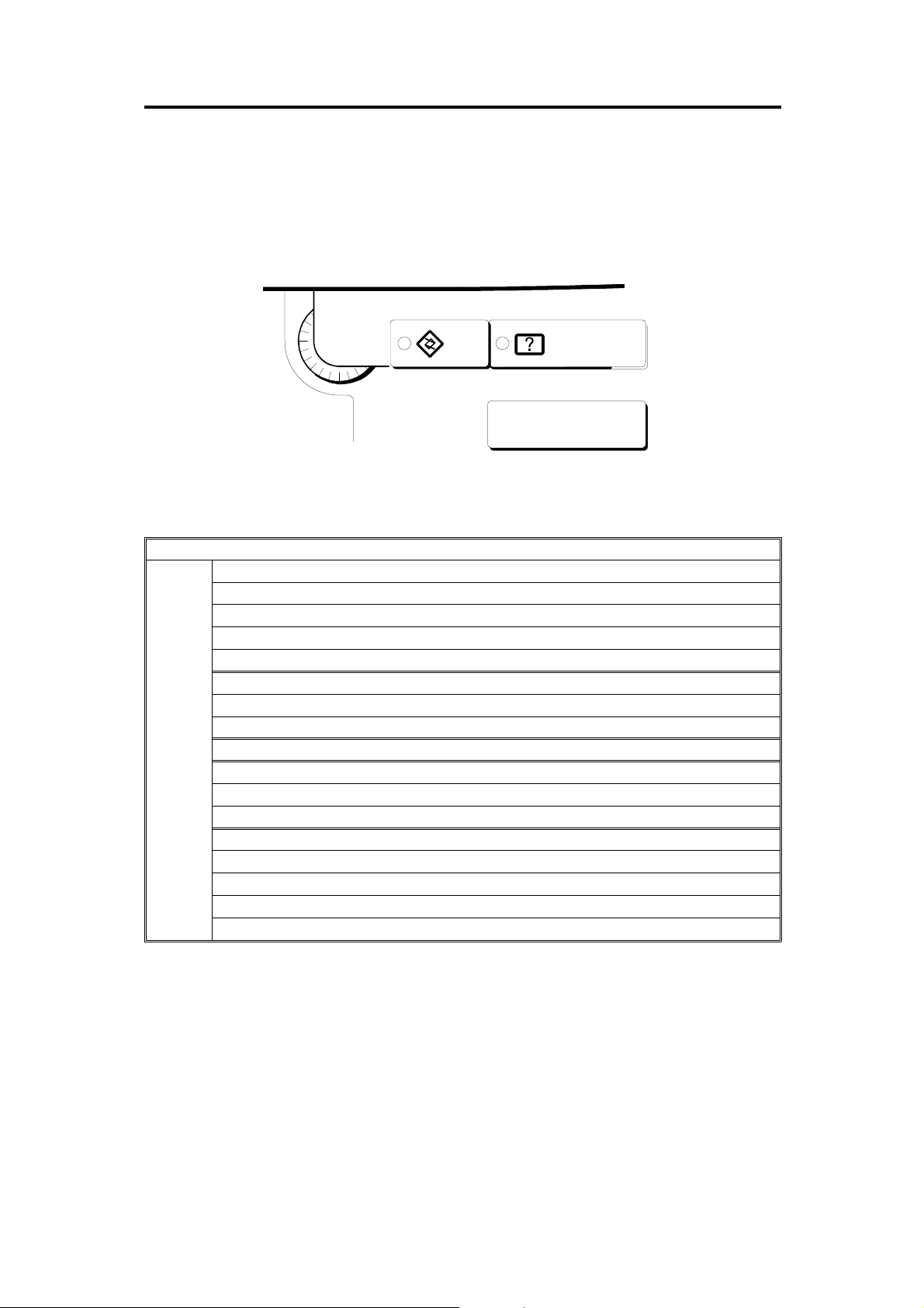
3. USER PROGRAM MODE
The user program (UP) m od e is accese d by th e key op er a to rs, an d sal e s
and service staff. This mode is used to input the copier’s default settings.
3.1 How to Enter and Leave UP Mode
Press the User Tools button
3.2 UP Mode Table
Auto Response (Human) Sensor
Operation Panel Beeper
Copy Counter Display
Set Date
Set Time
Auto Reset
Basic
Settings
Low Power Timer
Auto Off Timer
Paper Type Display (for each tray)
Tray 1 <*> Paper Size Setting
Tray 1 <F/F4> Paper Size Setting
Paper Size Setting (for tray 2,3, and 4 (Optional))
Paper Tray Priority
Original <F/F4> Size Setting
ADF: Thin Paper Mode
Auto Tray Switching
Set User Code(s)
User Tools
Menu
Guidance
A133/A217 4-36 FSM
 Loading...