

Afag RA-40-2F ZE, RA-40-4F ZE, RA-40, RA-40-4F, RA-40-2F-5E Operating Manual
...
Rotary axis RA-40
Operating manual
1 Content
1 Content .................................................................................................................................. 2
2 Preface .................................................................................................................................. 4
3 Safety information ................................................................................................................. 4
General safety information .............................................................................................. 4
Please observe the information in the operating instructions! ......................................... 4
Protection against dangerous movements ...................................................................... 5
Explanation of symbols and signs ................................................................................... 5
3.4.1 Warnings .................................................................................................................. 5
3.4.2 Symbols ................................................................................................................... 5
4 Product description ................................................................................................................ 6
Intended use ................................................................................................................... 6
Warranty and liability ....................................................................................................... 6
5 Rotary axis RA-40 ................................................................................................................. 7
RA-40-2F ........................................................................................................................ 8
RA-40-4F ...................................................................................................................... 10
RA-40-2F-5E ................................................................................................................. 12
RA-40-4F-5E ................................................................................................................. 14
6 Installation ........................................................................................................................... 16
7 Connection .......................................................................................................................... 17
Power supplies ............................................................................................................. 17
Controller C11x0 ........................................................................................................... 18
Controller C12x0 ........................................................................................................... 20
Controller E12x0 ........................................................................................................... 22
Controller E11x0 ........................................................................................................... 24
Controller B1100 ........................................................................................................... 26
Motor connector ............................................................................................................ 28
Plug configuration encoder ........................................................................................... 29
7.8.1 Round connector on the module ............................................................................ 29
7.8.2 Encoder plug configuration on the controller .......................................................... 29
Electrical feed-through / Proximity switch cable-R11 .................................................... 30
Y-distributor plug R12 ................................................................................................... 30
Reference sensor.......................................................................................................... 30
8 6 Commissioning ................................................................................................................. 31
Setting speeds of the electric axes ............................................................................... 31
Overview electrical axes ............................................................................................... 31
Teaching of positions on electric axes .......................................................................... 32
1.1 Switching distance ........................................................................................................ 32
1.1.1 Reference sensor with electric axes ....................................................................... 32
9 Maintenance ........................................................................................................................ 33
10 Repairs ................................................................................................................................ 33
11 Component/replacement part lists ....................................................................................... 34
Overview motor cabel-designation-axes-controller-application ..................................... 34
Subject to change. 2 Ver s. 1.1 en 01.01.2019
Afag Hardt GmbH – Gewerbestraße 11 - 78739 Hardt - Phone:07422/56003-0
Company headquarters: 78739 Hardt, Managing Director: Walter Kunz, HRB 480966 Stuttgart

Motor cable ................................................................................................................... 35
Encoder ........................................................................................................................ 36
Controller ...................................................................................................................... 36
12 Disposal instructions............................................................................................................ 37
13 Installation manual in accordance with Appendix VI (EC-RL 2006/42/EC) .......................... 38
14 Installation declaration for partly completed machinery (EC-RL 2006/42/EC) ..................... 39
15 Risk assessment (EG-RL 2006/42/EG) ............................................................................... 40
16 Support ................................................................................................................................ 45
17 Notes ................................................................................................................................... 46
Subject to change. 3 Ver s. 1.1 en 01.01.2019
Afag Hardt GmbH – Gewerbestraße 11 - 78739 Hardt - Phone:07422/56003-0
Company headquarters: 78739 Hardt, Managing Director: Walter Kunz, HRB 480966 Stuttgart

2 Preface
It is our aim to present all essential inform ation contained in these operating instruc tions as clearly
and concisely as possible. However, please do not hesitate to contact us should you have any queries.
We are always very grateful for your suggestions.
We wish you a successful integration of our devices into your machines or systems.
3 Safety information
General safety information
The pick and place EPS devices are constructed according to the state of the art and the
acknowledged safet y-related guidelines; they may only be used
for their intended purpose,
and only when in an operationally safe c ondition.
Please observe the information in the operati ng i nstructions!
The prerequisite for the safe handling and smooth operat ion of the pick and place EPS dev ices is
awareness of the fundam ental safety standards
Every person tasked with the installation, commissioning, maintenance and operation of the pick and
place EPS devices is required to have thoroughly read and understood the entire user manual,
particularly the "saf ety notes" chapter.
Furthermore, the rules and regulations on accident prevention applicable at the place of
installation/operation must also be observed. I m proper us e may result in dangers t o the life and limb
of the operator or third part ies and i n impairments to the machine or other assets.
In the event of faults that could impair safety, the machine must be switched off immediately and
secured to prevent restarting. The fault must then be remedied.
All work on the machines must be carried out with the m achines depressurised and disconnected
from the electrical power supply.
For the operation of t he machines, the user must provide prot ective covers, safety doors or other
safety precautions conf orming to the normal safety guidelines an d safety standards which prevent
people from entering or remaining in the working area of the machines during operation. The
machines may only be put into oper ation when the guards are securely closed.
Subject to change. 4 Ver s. 1.1 en 01.01.2019
Afag Hardt GmbH – Gewerbestraße 11 - 78739 Hardt - Phone:07422/56003-0
Company headquarters: 78739 Hardt, Managing Director: Walter Kunz, HRB 480966 Stuttgart
Danger
Warning
regulations are not
Caution
Information sign
! ! !
INFO
Protection against dangerous movements
Dangerous movements can occur if drives are actuated incorrectly. The drive components are
monitored so that a m alfunction c an be eff ectively ruled o ut. F or reasons of personal safet y, the risk
of injury and the risk of material damage, however, this must not be relied on exclusively. Faulty drive
movements must be anticipat ed until installed monitoring devices become go into effect.
Explanation of symbols and signs
The following warnings and symbols help readers understand
this manual quickly and ensur e that the EMD modules can be handled
safely.
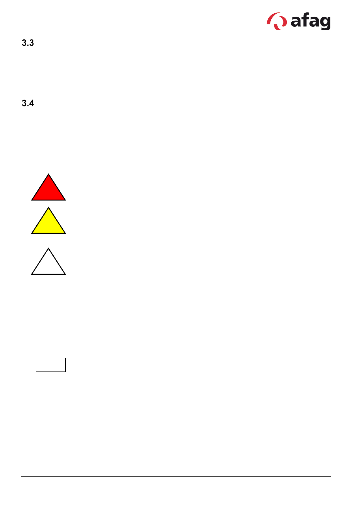
3.4.1 Warnings
This symbol draws attention t o an imminently hazardous situati on t hat will r esult in
serious personal injur y or even death if the safety regulations ar e not observed.
This symbol draws attention to a pot entially hazardous situation that will result in
serious personal injury or property damage if the safety
observed.
This symbol draws attention to a pot entially hazardous situation that will result in
property damage if the safety regulations are not observed.
3.4.2 Symbols
This symbol indicates information that contributes to bet ter understanding.
Subject to change. 5 Ver s. 1.1 en 01.01.2019
Afag Hardt GmbH – Gewerbestraße 11 - 78739 Hardt - Phone:07422/56003-0
Company headquarters: 78739 Hardt, Managing Director: Walter Kunz, HRB 480966 Stuttgart

4 Product description
Intended use
The pick and place EPS devices ar e used in automation systems and are intended exc lusively for
moving workpieces.
The pneumatic modules are intended exclusively for operation with compressed air (4-7 bar). Use for
any other purpose does not c onstitute an intended use.
The electric axes are intended exclusively for operation with original LinMot components (controllers,
cables...). Use for any other purpose does not constitute an int ended use.
The intended use also includes c om plianc e wit h t he prescr ibed i nstal lat ion and removal instructions,
the service and mainten anc e c onditions and observance of the specifications in the data sheets.
Warranty and liability
The "General Conditions of Sale and Delivery" of Afag GmbH shall apply in all cases.
The term of the warranty on Afag handling components and systems is:
24 months following commissioning, butnot exceeding 27 months following delivery.
Wear parts (e.g. shock absorbers) are excluded from the warranty. *
The guarantee covers the use or repair of defective Afag parts. No further claims will be
accepted.
The warranty will be voided in event of the following:
Use for other than the intended purpose
Failure to observe the information on installation, commissioning, operation and
maintenance in the operating manual
Improper installation, commissioning, operation and maintenance
Independent repairs and constructional changes without prior instruction by Afag
Automation AG/Afag Hardt GmbH
Removal of the serial number on the product
Using the module without shock absorbers, or with defective shock absorbers
Inadequate monitoring of wear parts
Failure to observe the EC Machinery Directive, accident prevention regulations, VDE
guidelines as well as the s afety/installation instr uc tions
Emergencies caused by external influence or force majeure.
*A customer has the right to a defect-free product. This is also applicable for accessories and
wear parts, if th ey are de fec ti ve.
Subject to change. 6 Ver s. 1.1 en 01.01.2019
Afag Hardt GmbH – Gewerbestraße 11 - 78739 Hardt - Phone:07422/56003-0
Company headquarters: 78739 Hardt, Managing Director: Walter Kunz, HRB 480966 Stuttgart
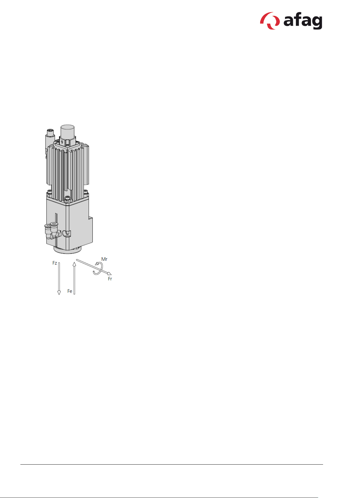
5 Rotary axis RA-40
Allgemein
Operating temperature: 0 - 50 °C
Bearing temperature: 0 - 50 °C
Humidity: < 90 %
Module stresses
Max. torque Mr: 10Nm
Max. press-in force Fe: 800N
Max. radial force: ±700N
Max. pulling force Fz: 350N
Subject to change. 7 Ver s. 1.1 en 01.01.2019
Afag Hardt GmbH – Gewerbestraße 11 - 78739 Hardt - Phone:07422/56003-0
Company headquarters: 78739 Hardt, Managing Director: Walter Kunz, HRB 480966 Stuttgart
Max. rotational speed
280 rpm
280 rpm
280 rpm
280 rpm
Fluid passages
2 2 2 2 Continuous torque
1.2 Nm
1.2 Nm
1.2 Nm
1.2 Nm
61440 Inc/U
61440 Inc/U
Mounting position
Angle of rotation
∞ ∞ ∞ ∞ Max. rotational speed
140 rpm
140 rpm
140 rpm
140 rpm
Fluid passages
2 2 2
2
102400 Inc/U
102400 Inc/U
Mounting position
RA-40-2F
Type RA-40-2F-30-G RA-40-2F-30-W RA-40-2F-30-G-ZE RA-40-2F-30-W-ZE
Order number 50473180 50473182 50473183 50473184
Net weight 0.69 kg 0.69 kg 0.74 kg 0.74 kg
Angle of rotation ∞ ∞ ∞ ∞
Max. output torque 2.4 Nm 2.4 Nm 2.4 Nm 2.4 Nm
Ratio 30:1 30:1 30:1 30:1
Repeat accuracy +/- 0.0017 ° +/- 0.0017 ° +/- 0.0017 ° +/- 0.0017 °
Encoder
SV-TLL ABZ,
SV-TLL ABZ,
Type RA-40-2F-50-G RA-40-2F-50-W RA-40-2F-50-G-ZE RA-40-2F-50-W-ZE
Order number 50473185 50473186 50473187 50473188
Net weight 0.69 kg 0.69 kg 0.74 kg 0.74 kg
Continuous torque 2 Nm 2 Nm 2 Nm 2 Nm
Max. output torque 4 Nm 4 Nm 4 Nm 4 Nm
Ratio 50:1 50:1 50:1 50:1
Repeat accuracy +/- 0.0017 ° +/- 0.0017 ° +/- 0.0017 ° +/- 0.0017 °
Encoder
SV-TLL ABZ,
SV-TLL ABZ,
The technical data pertains to Afag standard test conditions. Air purity class 5 (ISO 14644-1)
Cleanroom class: 10 000 (Federal Standard 209E )
In the article description of a rotary axis the “F” stands for fluid passages and the “E” for electrical feed-through. There are two
version of motor plugs. A „G“ in the article description of the rotary axis stand for a straight and the „W“ for an angular plug. Also
see order key for RA-40.
Subject to change. 8 Ver s. 1.1 en 01.01.2019
Afag Hardt GmbH – Gewerbestraße 11 - 78739 Hardt - Phone:07422/56003-0
Company headquarters: 78739 Hardt, Managing Director: Walter Kunz, HRB 480966 Stuttgart
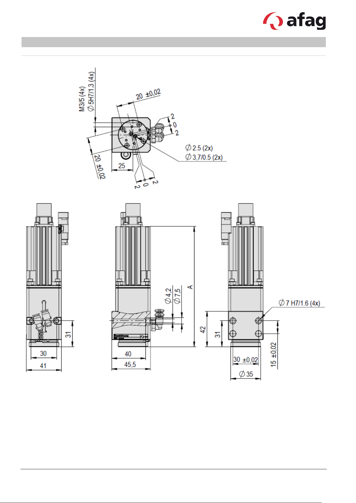
A
141 mm
159 mm
Type RA-40-2F RA-40-2F (ZE)
Subject to change. 9 Ver s. 1.1 en 01.01.2019
Afag Hardt GmbH – Gewerbestraße 11 - 78739 Hardt - Phone:07422/56003-0
Company headquarters: 78739 Hardt, Managing Director: Walter Kunz, HRB 480966 Stuttgart

Max. rotational speed
280 rpm
280 rpm
280 rpm
280 rpm
Fluid passages
2 2 2 2 Continuous torque
1.2 Nm
1.2 Nm
1.2 Nm
1.2 Nm
61440 Inc/U
61440 Inc/U
Mounting position
Angle of rotation
∞ ∞ ∞ ∞ Max. rotational speed
140 rpm
140 rpm
140 rpm
140 rpm
Fluid passages
2 2 2
2
102400 Inc/U
102400 Inc/U
Mounting position
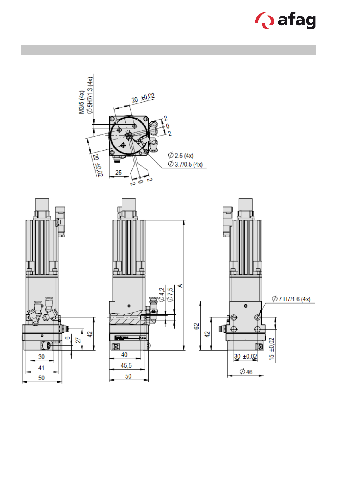
RA-40-4F
Type RA-40-4F-30-G RA-40-4F-30-W RA-40-4F-30-G-ZE RA-40-4F-30-W-ZE
Order number 50473189 50473190 50473191 50473192
Net weight 0.74 kg 0.74 kg 0.79 kg 0.79 kg
Angle of rotation ∞ ∞ ∞ ∞
Max. output torque 2.4 Nm 2.4 Nm 2.4 Nm 2.4 Nm
Ratio 30:1 30:1 30:1 30:1
Repeat accuracy +/- 0.0017 ° +/- 0.0017 ° +/- 0.0017 ° +/- 0.0017 °
Encoder
SV-TLL ABZ,
SV-TLL ABZ,
Type RA-40-4F-50-G RA-40-4F-50-W RA-40-4F-50-G-ZE RA-40-4F-50-W-ZE
Order number 50473193 50473194 50473195 50473196
Net weight 0.74 kg 0.74 kg 0.79 kg 0.79 kg
Continuous torque 2 Nm 2 Nm 2 Nm 2 Nm
Max. output torque 4 Nm 4 Nm 4 Nm 4 Nm
Ratio 50:1 50:1 50:1 50:1
Repeat accuracy +/- 0.0017 ° +/- 0.0017 ° +/- 0.0017 ° +/- 0.0017 °
Encoder
SV-TLL ABZ,
SV-TLL ABZ,
The technical data pertains to Afag standard test conditions. Air purity class 5 (ISO 14644-1)
Cleanroom class: 10 000 (Federal Standard 209E )
In the article description of a rotary axis the “F” stands for fluid passages and the “E” for electrical feed-through. There are two
version of motor plugs. A „G“ in the article description of the rotary axis stand for a straight and the „W“ for an angular plug. Also
see order key for RA-40.
Subject to change. 10 Vers. 1. 1 en 01.01.2019
Afag Hardt GmbH – Gewerbestraße 11 - 78739 Hardt - Phone:07422/56003-0
Company headquarters: 78739 Hardt, Managing Director: Walter Kunz, HRB 480966 Stuttgart

A
151 mm
169 mm
Type RA-40-4F RA-40-4F (ZE)
Subject to change. 11 Vers. 1. 1 en 01.01.2019
Afag Hardt GmbH – Gewerbestraße 11 - 78739 Hardt - Phone:07422/56003-0
Company headquarters: 78739 Hardt, Managing Director: Walter Kunz, HRB 480966 Stuttgart
30-G-ZE
30-W-ZE
Net weight
0.84 kg
0.84 kg
0.89 kg
0.89 kg
Angle of rotation
∞ ∞ ∞
∞
Max. rotational speed
280 rpm
280 rpm
280 rpm
280 rpm
Elektrische Durchführungen
5 x 2 A
5 x 2 A
5 x 2 A
5 x 2 A
Repeat accuracy
+/- 0.0017 °
+/- 0.0017 °
+/- 0.0017 °
+/- 0.0017 °
61440 Inc/U
61440 Inc/U
Mounting position
50-G-ZE
50-W-ZE
Net weight
0.84 kg
0.84 kg
0.89 kg
0.89 kg
Angle of rotation
∞ ∞ ∞
∞
Continuous torque
2 Nm
2 Nm
2 Nm
2 Nm
Max. output torque
4 Nm
4 Nm
4 Nm
4 Nm
Ratio
50:1
50:1
50:1
50:1
102400 Inc/U
102400 Inc/U
RA-40-2F-5E
Type RA-40-2F-5E-30-G RA-40-2F-5E-30-W RA-40-2F-5E-
Order number 50473197 50473198 50473200 50473201
Fluid passages 2 2 2 2
Continuous torque 1.2 Nm 1.2 Nm 1.2 Nm 1.2 Nm
Max. output torque 2.4 Nm 2.4 Nm 2.4 Nm 2.4 Nm
Ratio 30:1 30:1 30:1 30:1
RA-40-2F-5E-
Encoder
SV-TLL ABZ,
Type RA-40-2F-5E-50-G RA-40-2F-5E-50-W RA-40-2F-5E-
SV-TLL ABZ,
RA-40-2F-5E-
Order number 50473202 50473203 50473204 50473205
Max. rotational speed 140 rpm 140 rpm 140 rpm 140 rpm
Elektrische Durchführungen 5 x 2 A 5 x 2 A 5 x 2 A 5 x 2 A
Fluid passages 2 2 2 2
Repeat accuracy +/- 0.0017 ° +/- 0.0017 ° +/- 0.0017 ° +/- 0.0017 °
Encoder
SV-TLL ABZ,
SV-TLL ABZ,
Mounting position
The technical data pertains to Afag standard test conditions. Air purity class 5 (ISO 14644-1)
Cleanroom class: 10 000 (Federal Standard 209E )
In the article description of a rotary axis the “F” stands for fluid passages and the “E” for electrical feed-through. There are two
version of motor plugs. A „G“ in the article description of the rotary axis stand for a straight and the „W“ for an angular plug. Also
see order key for RA-40.
Subject to change. 12 Vers. 1. 1 en 01.01.2019
Afag Hardt GmbH – Gewerbestraße 11 - 78739 Hardt - Phone:07422/56003-0
Company headquarters: 78739 Hardt, Managing Director: Walter Kunz, HRB 480966 Stuttgart
A
155 mm
173 mm
Type RA-40-2F-5E RA-40-2F-5E (ZE)
Subject to change. 13 Vers. 1. 1 en 01.01.2019
Afag Hardt GmbH – Gewerbestraße 11 - 78739 Hardt - Phone:07422/56003-0
Company headquarters: 78739 Hardt, Managing Director: Walter Kunz, HRB 480966 Stuttgart

30-G-ZE
30-W-ZE
Net weight
0.84 kg
0.84 kg
0.89 kg
0.89 kg
Angle of rotation
∞ ∞ ∞
∞
Max. rotational speed
280 rpm
280 rpm
280 rpm
280 rpm
Elektrische Durchführungen
5 x 2 A
5 x 2 A
5 x 2 A
5 x 2 A
Repeat accuracy
+/- 0.0017 °
+/- 0.0017 °
+/- 0.0017 °
+/- 0.0017 °
61440 Inc/U
61440 Inc/U
Mounting position
50-G-ZE
50-W-ZE
Net weight
0.84 kg
0.84 kg
0.89 kg
0.89 kg
Angle of rotation
∞ ∞ ∞
∞
Continuous torque
2 Nm
2 Nm
2 Nm
2 Nm
Max. output torque
4 Nm
4 Nm
4 Nm
4 Nm
Ratio
50:1
50:1
50:1
50:1
102400 Inc/U
102400 Inc/U
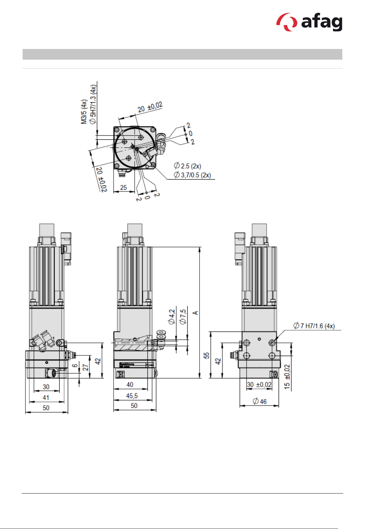
RA-40-4F-5E
Type RA-40-4F-5E-30-G RA-40-4F-5E-30-W RA-40-4F-5E-
Order number 50473206 50473207 50473208 50473209
Fluid passages 4 4 4 4
Continuous torque 1.2 Nm 1.2 Nm 1.2 Nm 1.2 Nm
Max. output torque 2.4 Nm 2.4 Nm 2.4 Nm 2.4 Nm
Ratio 30:1 30:1 30:1 30:1
RA-40-4F-5E-
Encoder
SV-TLL ABZ,
Type RA-40-4F-5E-50-G RA-40-4F-5E-50-W RA-40-4F-5E-
SV-TLL ABZ,
RA-40-4F-5E-
Order number 50473210 50473211 50473212 50473213
Max. rotational speed 140 rpm 140 rpm 140 rpm 140 rpm
Elektrische Durchführungen 5 x 2 A 5 x 2 A 5 x 2 A 5 x 2 A
Fluid passages 4 4 4 4
Repeat accuracy +/- 0.0017 ° +/- 0.0017 ° +/- 0.0017 ° +/- 0.0017 °
Encoder
SV-TLL ABZ,
SV-TLL ABZ,
Mounting position
The technical data pertains to Afag standard test conditions. Air purity class 5 (ISO 14644-1)
Cleanroom class: 10 000 (Federal Standard 209E)
In the article description of a rotary axis the “F” stands for fluid passages and the “E” for electrical feed-through. There are two
version of motor plugs. A „G“ in the article description of the rotary axis stand for a straight and the „W“ for an angular plug. Also
see order key for RA-40.
Subject to change. 14 Vers. 1. 1 en 01.01.2019
Afag Hardt GmbH – Gewerbestraße 11 - 78739 Hardt - Phone:07422/56003-0
Company headquarters: 78739 Hardt, Managing Director: Walter Kunz, HRB 480966 Stuttgart
A
165 mm
183 mm
Type RA-40-4F-5E RA-40-4F-5E (ZE)
Subject to change. 15 Vers. 1. 1 en 01.01.2019
Afag Hardt GmbH – Gewerbestraße 11 - 78739 Hardt - Phone:07422/56003-0
Company headquarters: 78739 Hardt, Managing Director: Walter Kunz, HRB 480966 Stuttgart
 Loading...