

Rotary axis RA-40
Operating manual
1 Content
1 Content .................................................................................................................................. 2
2 Preface .................................................................................................................................. 4
3 Safety information ................................................................................................................. 4
General safety information .............................................................................................. 4
Please observe the information in the operating instructions! ......................................... 4
Protection against dangerous movements ...................................................................... 5
Explanation of symbols and signs ................................................................................... 5
3.4.1 Warnings .................................................................................................................. 5
3.4.2 Symbols ................................................................................................................... 5
4 Product description ................................................................................................................ 6
Intended use ................................................................................................................... 6
Warranty and liability ....................................................................................................... 6
5 Rotary axis RA-40 ................................................................................................................. 7
RA-40-2F ........................................................................................................................ 8
RA-40-4F ...................................................................................................................... 10
RA-40-2F-5E ................................................................................................................. 12
RA-40-4F-5E ................................................................................................................. 14
6 Installation ........................................................................................................................... 16
7 Connection .......................................................................................................................... 17
Power supplies ............................................................................................................. 17
Controller C11x0 ........................................................................................................... 18
Controller C12x0 ........................................................................................................... 20
Controller E12x0 ........................................................................................................... 22
Controller E11x0 ........................................................................................................... 24
Controller B1100 ........................................................................................................... 26
Motor connector ............................................................................................................ 28
Plug configuration encoder ........................................................................................... 29
7.8.1 Round connector on the module ............................................................................ 29
7.8.2 Encoder plug configuration on the controller .......................................................... 29
Electrical feed-through / Proximity switch cable-R11 .................................................... 30
Y-distributor plug R12 ................................................................................................... 30
Reference sensor.......................................................................................................... 30
8 6 Commissioning ................................................................................................................. 31
Setting speeds of the electric axes ............................................................................... 31
Overview electrical axes ............................................................................................... 31
Teaching of positions on electric axes .......................................................................... 32
1.1 Switching distance ........................................................................................................ 32
1.1.1 Reference sensor with electric axes ....................................................................... 32
9 Maintenance ........................................................................................................................ 33
10 Repairs ................................................................................................................................ 33
11 Component/replacement part lists ....................................................................................... 34
Overview motor cabel-designation-axes-controller-application ..................................... 34
Subject to change. 2 Ver s. 1.1 en 01.01.2019
Afag Hardt GmbH – Gewerbestraße 11 - 78739 Hardt - Phone:07422/56003-0
Company headquarters: 78739 Hardt, Managing Director: Walter Kunz, HRB 480966 Stuttgart

Motor cable ................................................................................................................... 35
Encoder ........................................................................................................................ 36
Controller ...................................................................................................................... 36
12 Disposal instructions............................................................................................................ 37
13 Installation manual in accordance with Appendix VI (EC-RL 2006/42/EC) .......................... 38
14 Installation declaration for partly completed machinery (EC-RL 2006/42/EC) ..................... 39
15 Risk assessment (EG-RL 2006/42/EG) ............................................................................... 40
16 Support ................................................................................................................................ 45
17 Notes ................................................................................................................................... 46
Subject to change. 3 Ver s. 1.1 en 01.01.2019
Afag Hardt GmbH – Gewerbestraße 11 - 78739 Hardt - Phone:07422/56003-0
Company headquarters: 78739 Hardt, Managing Director: Walter Kunz, HRB 480966 Stuttgart

2 Preface
It is our aim to present all essential inform ation contained in these operating instruc tions as clearly
and concisely as possible. However, please do not hesitate to contact us should you have any queries.
We are always very grateful for your suggestions.
We wish you a successful integration of our devices into your machines or systems.
3 Safety information
General safety information
The pick and place EPS devices are constructed according to the state of the art and the
acknowledged safet y-related guidelines; they may only be used
for their intended purpose,
and only when in an operationally safe c ondition.
Please observe the information in the operati ng i nstructions!
The prerequisite for the safe handling and smooth operat ion of the pick and place EPS dev ices is
awareness of the fundam ental safety standards
Every person tasked with the installation, commissioning, maintenance and operation of the pick and
place EPS devices is required to have thoroughly read and understood the entire user manual,
particularly the "saf ety notes" chapter.
Furthermore, the rules and regulations on accident prevention applicable at the place of
installation/operation must also be observed. I m proper us e may result in dangers t o the life and limb
of the operator or third part ies and i n impairments to the machine or other assets.
In the event of faults that could impair safety, the machine must be switched off immediately and
secured to prevent restarting. The fault must then be remedied.
All work on the machines must be carried out with the m achines depressurised and disconnected
from the electrical power supply.
For the operation of t he machines, the user must provide prot ective covers, safety doors or other
safety precautions conf orming to the normal safety guidelines an d safety standards which prevent
people from entering or remaining in the working area of the machines during operation. The
machines may only be put into oper ation when the guards are securely closed.
Subject to change. 4 Ver s. 1.1 en 01.01.2019
Afag Hardt GmbH – Gewerbestraße 11 - 78739 Hardt - Phone:07422/56003-0
Company headquarters: 78739 Hardt, Managing Director: Walter Kunz, HRB 480966 Stuttgart
Danger
Warning
regulations are not
Caution
Information sign
! ! !
INFO
Protection against dangerous movements
Dangerous movements can occur if drives are actuated incorrectly. The drive components are
monitored so that a m alfunction c an be eff ectively ruled o ut. F or reasons of personal safet y, the risk
of injury and the risk of material damage, however, this must not be relied on exclusively. Faulty drive
movements must be anticipat ed until installed monitoring devices become go into effect.
Explanation of symbols and signs
The following warnings and symbols help readers understand
this manual quickly and ensur e that the EMD modules can be handled
safely.
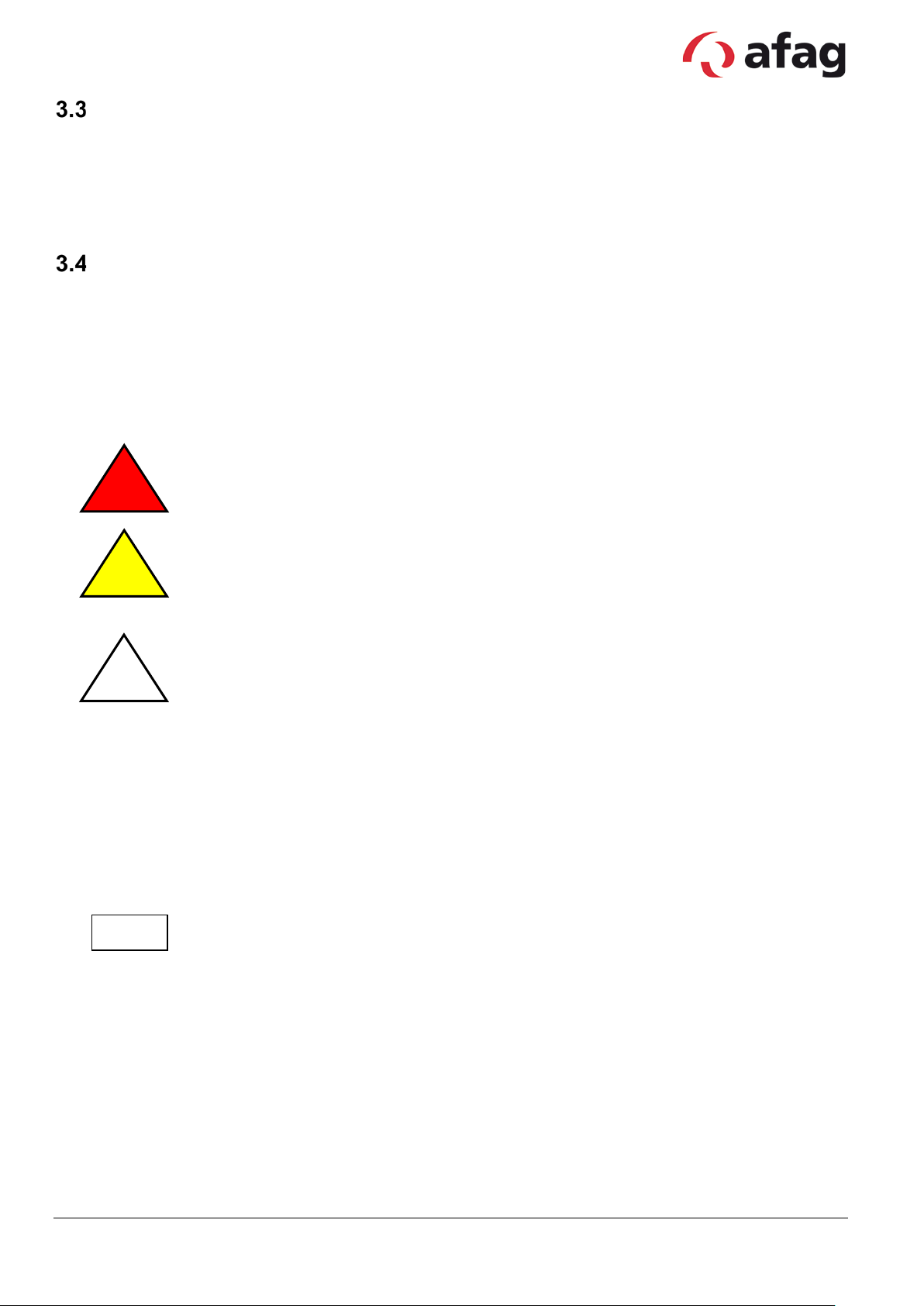
3.4.1 Warnings
This symbol draws attention t o an imminently hazardous situati on t hat will r esult in
serious personal injur y or even death if the safety regulations ar e not observed.
This symbol draws attention to a pot entially hazardous situation that will result in
serious personal injury or property damage if the safety
observed.
This symbol draws attention to a pot entially hazardous situation that will result in
property damage if the safety regulations are not observed.
3.4.2 Symbols
This symbol indicates information that contributes to bet ter understanding.
Subject to change. 5 Ver s. 1.1 en 01.01.2019
Afag Hardt GmbH – Gewerbestraße 11 - 78739 Hardt - Phone:07422/56003-0
Company headquarters: 78739 Hardt, Managing Director: Walter Kunz, HRB 480966 Stuttgart

4 Product description
Intended use
The pick and place EPS devices ar e used in automation systems and are intended exc lusively for
moving workpieces.
The pneumatic modules are intended exclusively for operation with compressed air (4-7 bar). Use for
any other purpose does not c onstitute an intended use.
The electric axes are intended exclusively for operation with original LinMot components (controllers,
cables...). Use for any other purpose does not constitute an int ended use.
The intended use also includes c om plianc e wit h t he prescr ibed i nstal lat ion and removal instructions,
the service and mainten anc e c onditions and observance of the specifications in the data sheets.
Warranty and liability
The "General Conditions of Sale and Delivery" of Afag GmbH shall apply in all cases.
The term of the warranty on Afag handling components and systems is:
24 months following commissioning, butnot exceeding 27 months following delivery.
Wear parts (e.g. shock absorbers) are excluded from the warranty. *
The guarantee covers the use or repair of defective Afag parts. No further claims will be
accepted.
The warranty will be voided in event of the following:
Use for other than the intended purpose
Failure to observe the information on installation, commissioning, operation and
maintenance in the operating manual
Improper installation, commissioning, operation and maintenance
Independent repairs and constructional changes without prior instruction by Afag
Automation AG/Afag Hardt GmbH
Removal of the serial number on the product
Using the module without shock absorbers, or with defective shock absorbers
Inadequate monitoring of wear parts
Failure to observe the EC Machinery Directive, accident prevention regulations, VDE
guidelines as well as the s afety/installation instr uc tions
Emergencies caused by external influence or force majeure.
*A customer has the right to a defect-free product. This is also applicable for accessories and
wear parts, if th ey are de fec ti ve.
Subject to change. 6 Ver s. 1.1 en 01.01.2019
Afag Hardt GmbH – Gewerbestraße 11 - 78739 Hardt - Phone:07422/56003-0
Company headquarters: 78739 Hardt, Managing Director: Walter Kunz, HRB 480966 Stuttgart
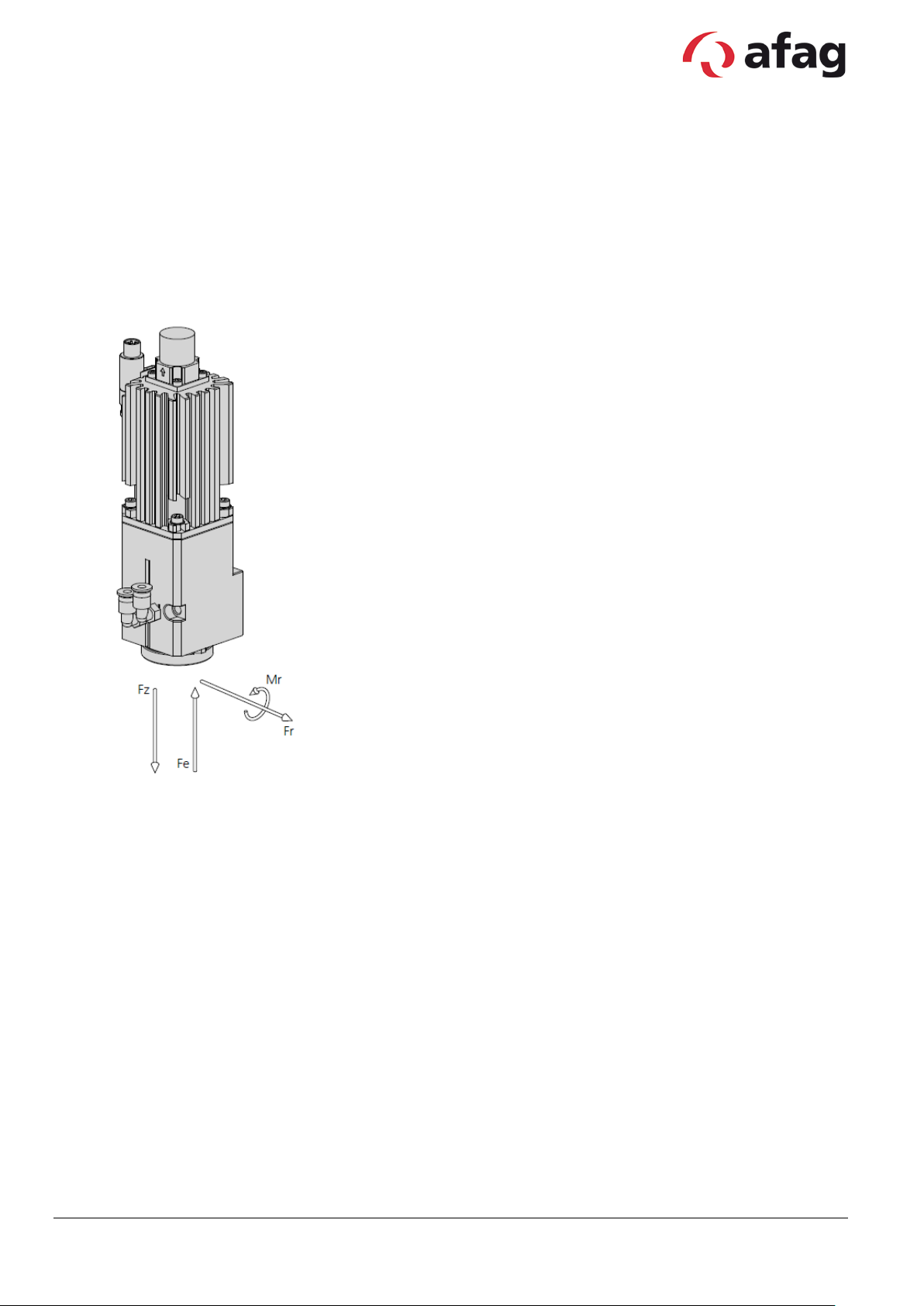
5 Rotary axis RA-40
Allgemein
Operating temperature: 0 - 50 °C
Bearing temperature: 0 - 50 °C
Humidity: < 90 %
Module stresses
Max. torque Mr: 10Nm
Max. press-in force Fe: 800N
Max. radial force: ±700N
Max. pulling force Fz: 350N
Subject to change. 7 Ver s. 1.1 en 01.01.2019
Afag Hardt GmbH – Gewerbestraße 11 - 78739 Hardt - Phone:07422/56003-0
Company headquarters: 78739 Hardt, Managing Director: Walter Kunz, HRB 480966 Stuttgart
Max. rotational speed
280 rpm
280 rpm
280 rpm
280 rpm
Fluid passages
2 2 2 2 Continuous torque
1.2 Nm
1.2 Nm
1.2 Nm
1.2 Nm
61440 Inc/U
61440 Inc/U
Mounting position
Angle of rotation
∞ ∞ ∞ ∞ Max. rotational speed
140 rpm
140 rpm
140 rpm
140 rpm
Fluid passages
2 2 2
2
102400 Inc/U
102400 Inc/U
Mounting position
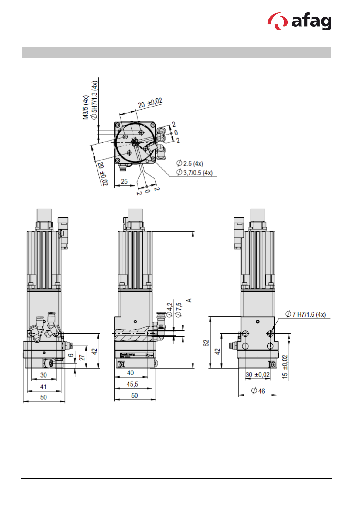
RA-40-2F
Type RA-40-2F-30-G RA-40-2F-30-W RA-40-2F-30-G-ZE RA-40-2F-30-W-ZE
Order number 50473180 50473182 50473183 50473184
Net weight 0.69 kg 0.69 kg 0.74 kg 0.74 kg
Angle of rotation ∞ ∞ ∞ ∞
Max. output torque 2.4 Nm 2.4 Nm 2.4 Nm 2.4 Nm
Ratio 30:1 30:1 30:1 30:1
Repeat accuracy +/- 0.0017 ° +/- 0.0017 ° +/- 0.0017 ° +/- 0.0017 °
Encoder
SV-TLL ABZ,
SV-TLL ABZ,
Type RA-40-2F-50-G RA-40-2F-50-W RA-40-2F-50-G-ZE RA-40-2F-50-W-ZE
Order number 50473185 50473186 50473187 50473188
Net weight 0.69 kg 0.69 kg 0.74 kg 0.74 kg
Continuous torque 2 Nm 2 Nm 2 Nm 2 Nm
Max. output torque 4 Nm 4 Nm 4 Nm 4 Nm
Ratio 50:1 50:1 50:1 50:1
Repeat accuracy +/- 0.0017 ° +/- 0.0017 ° +/- 0.0017 ° +/- 0.0017 °
Encoder
SV-TLL ABZ,
SV-TLL ABZ,
The technical data pertains to Afag standard test conditions. Air purity class 5 (ISO 14644-1)
Cleanroom class: 10 000 (Federal Standard 209E )
In the article description of a rotary axis the “F” stands for fluid passages and the “E” for electrical feed-through. There are two
version of motor plugs. A „G“ in the article description of the rotary axis stand for a straight and the „W“ for an angular plug. Also
see order key for RA-40.
Subject to change. 8 Ver s. 1.1 en 01.01.2019
Afag Hardt GmbH – Gewerbestraße 11 - 78739 Hardt - Phone:07422/56003-0
Company headquarters: 78739 Hardt, Managing Director: Walter Kunz, HRB 480966 Stuttgart
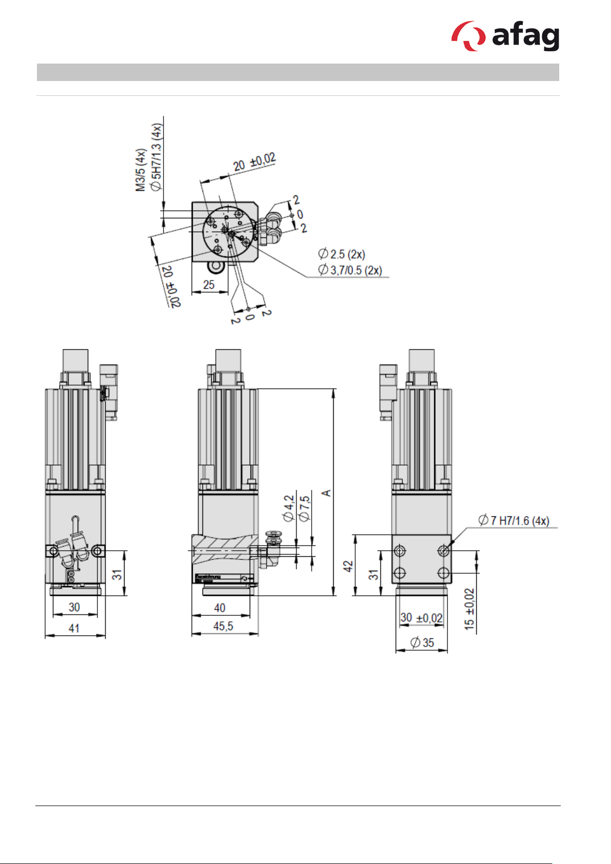
A
141 mm
159 mm
Type RA-40-2F RA-40-2F (ZE)
Subject to change. 9 Ver s. 1.1 en 01.01.2019
Afag Hardt GmbH – Gewerbestraße 11 - 78739 Hardt - Phone:07422/56003-0
Company headquarters: 78739 Hardt, Managing Director: Walter Kunz, HRB 480966 Stuttgart

Max. rotational speed
280 rpm
280 rpm
280 rpm
280 rpm
Fluid passages
2 2 2 2 Continuous torque
1.2 Nm
1.2 Nm
1.2 Nm
1.2 Nm
61440 Inc/U
61440 Inc/U
Mounting position
Angle of rotation
∞ ∞ ∞ ∞ Max. rotational speed
140 rpm
140 rpm
140 rpm
140 rpm
Fluid passages
2 2 2
2
102400 Inc/U
102400 Inc/U
Mounting position
RA-40-4F
Type RA-40-4F-30-G RA-40-4F-30-W RA-40-4F-30-G-ZE RA-40-4F-30-W-ZE
Order number 50473189 50473190 50473191 50473192
Net weight 0.74 kg 0.74 kg 0.79 kg 0.79 kg
Angle of rotation ∞ ∞ ∞ ∞
Max. output torque 2.4 Nm 2.4 Nm 2.4 Nm 2.4 Nm
Ratio 30:1 30:1 30:1 30:1
Repeat accuracy +/- 0.0017 ° +/- 0.0017 ° +/- 0.0017 ° +/- 0.0017 °
Encoder
SV-TLL ABZ,
SV-TLL ABZ,
Type RA-40-4F-50-G RA-40-4F-50-W RA-40-4F-50-G-ZE RA-40-4F-50-W-ZE
Order number 50473193 50473194 50473195 50473196
Net weight 0.74 kg 0.74 kg 0.79 kg 0.79 kg
Continuous torque 2 Nm 2 Nm 2 Nm 2 Nm
Max. output torque 4 Nm 4 Nm 4 Nm 4 Nm
Ratio 50:1 50:1 50:1 50:1
Repeat accuracy +/- 0.0017 ° +/- 0.0017 ° +/- 0.0017 ° +/- 0.0017 °
Encoder
SV-TLL ABZ,
SV-TLL ABZ,
The technical data pertains to Afag standard test conditions. Air purity class 5 (ISO 14644-1)
Cleanroom class: 10 000 (Federal Standard 209E )
In the article description of a rotary axis the “F” stands for fluid passages and the “E” for electrical feed-through. There are two
version of motor plugs. A „G“ in the article description of the rotary axis stand for a straight and the „W“ for an angular plug. Also
see order key for RA-40.
Subject to change. 10 Vers. 1. 1 en 01.01.2019
Afag Hardt GmbH – Gewerbestraße 11 - 78739 Hardt - Phone:07422/56003-0
Company headquarters: 78739 Hardt, Managing Director: Walter Kunz, HRB 480966 Stuttgart

A
151 mm
169 mm
Type RA-40-4F RA-40-4F (ZE)
Subject to change. 11 Vers. 1. 1 en 01.01.2019
Afag Hardt GmbH – Gewerbestraße 11 - 78739 Hardt - Phone:07422/56003-0
Company headquarters: 78739 Hardt, Managing Director: Walter Kunz, HRB 480966 Stuttgart
30-G-ZE
30-W-ZE
Net weight
0.84 kg
0.84 kg
0.89 kg
0.89 kg
Angle of rotation
∞ ∞ ∞
∞
Max. rotational speed
280 rpm
280 rpm
280 rpm
280 rpm
Elektrische Durchführungen
5 x 2 A
5 x 2 A
5 x 2 A
5 x 2 A
Repeat accuracy
+/- 0.0017 °
+/- 0.0017 °
+/- 0.0017 °
+/- 0.0017 °
61440 Inc/U
61440 Inc/U
Mounting position
50-G-ZE
50-W-ZE
Net weight
0.84 kg
0.84 kg
0.89 kg
0.89 kg
Angle of rotation
∞ ∞ ∞
∞
Continuous torque
2 Nm
2 Nm
2 Nm
2 Nm
Max. output torque
4 Nm
4 Nm
4 Nm
4 Nm
Ratio
50:1
50:1
50:1
50:1
102400 Inc/U
102400 Inc/U
RA-40-2F-5E
Type RA-40-2F-5E-30-G RA-40-2F-5E-30-W RA-40-2F-5E-
Order number 50473197 50473198 50473200 50473201
Fluid passages 2 2 2 2
Continuous torque 1.2 Nm 1.2 Nm 1.2 Nm 1.2 Nm
Max. output torque 2.4 Nm 2.4 Nm 2.4 Nm 2.4 Nm
Ratio 30:1 30:1 30:1 30:1
RA-40-2F-5E-
Encoder
SV-TLL ABZ,
Type RA-40-2F-5E-50-G RA-40-2F-5E-50-W RA-40-2F-5E-
SV-TLL ABZ,
RA-40-2F-5E-
Order number 50473202 50473203 50473204 50473205
Max. rotational speed 140 rpm 140 rpm 140 rpm 140 rpm
Elektrische Durchführungen 5 x 2 A 5 x 2 A 5 x 2 A 5 x 2 A
Fluid passages 2 2 2 2
Repeat accuracy +/- 0.0017 ° +/- 0.0017 ° +/- 0.0017 ° +/- 0.0017 °
Encoder
SV-TLL ABZ,
SV-TLL ABZ,
Mounting position
The technical data pertains to Afag standard test conditions. Air purity class 5 (ISO 14644-1)
Cleanroom class: 10 000 (Federal Standard 209E )
In the article description of a rotary axis the “F” stands for fluid passages and the “E” for electrical feed-through. There are two
version of motor plugs. A „G“ in the article description of the rotary axis stand for a straight and the „W“ for an angular plug. Also
see order key for RA-40.
Subject to change. 12 Vers. 1. 1 en 01.01.2019
Afag Hardt GmbH – Gewerbestraße 11 - 78739 Hardt - Phone:07422/56003-0
Company headquarters: 78739 Hardt, Managing Director: Walter Kunz, HRB 480966 Stuttgart
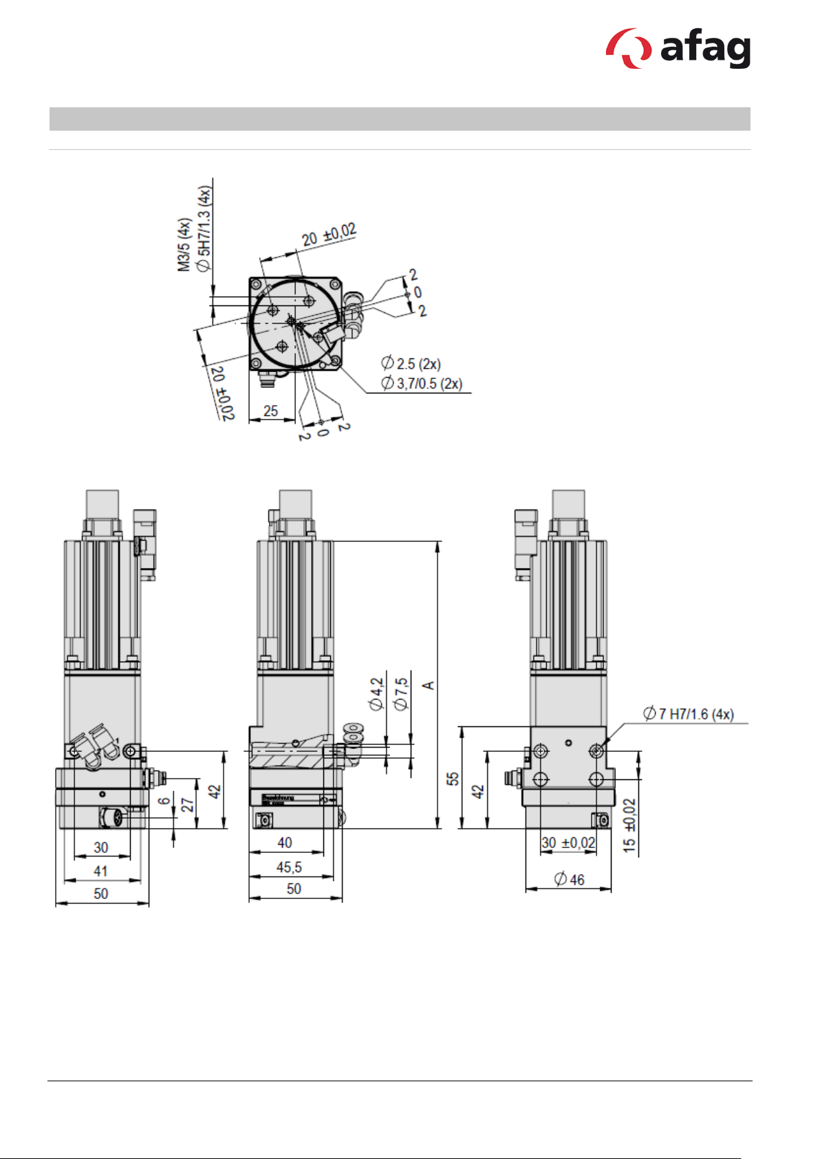
A
155 mm
173 mm
Type RA-40-2F-5E RA-40-2F-5E (ZE)
Subject to change. 13 Vers. 1. 1 en 01.01.2019
Afag Hardt GmbH – Gewerbestraße 11 - 78739 Hardt - Phone:07422/56003-0
Company headquarters: 78739 Hardt, Managing Director: Walter Kunz, HRB 480966 Stuttgart

30-G-ZE
30-W-ZE
Net weight
0.84 kg
0.84 kg
0.89 kg
0.89 kg
Angle of rotation
∞ ∞ ∞
∞
Max. rotational speed
280 rpm
280 rpm
280 rpm
280 rpm
Elektrische Durchführungen
5 x 2 A
5 x 2 A
5 x 2 A
5 x 2 A
Repeat accuracy
+/- 0.0017 °
+/- 0.0017 °
+/- 0.0017 °
+/- 0.0017 °
61440 Inc/U
61440 Inc/U
Mounting position
50-G-ZE
50-W-ZE
Net weight
0.84 kg
0.84 kg
0.89 kg
0.89 kg
Angle of rotation
∞ ∞ ∞
∞
Continuous torque
2 Nm
2 Nm
2 Nm
2 Nm
Max. output torque
4 Nm
4 Nm
4 Nm
4 Nm
Ratio
50:1
50:1
50:1
50:1
102400 Inc/U
102400 Inc/U
RA-40-4F-5E
Type RA-40-4F-5E-30-G RA-40-4F-5E-30-W RA-40-4F-5E-
Order number 50473206 50473207 50473208 50473209
Fluid passages 4 4 4 4
Continuous torque 1.2 Nm 1.2 Nm 1.2 Nm 1.2 Nm
Max. output torque 2.4 Nm 2.4 Nm 2.4 Nm 2.4 Nm
Ratio 30:1 30:1 30:1 30:1
RA-40-4F-5E-
Encoder
SV-TLL ABZ,
Type RA-40-4F-5E-50-G RA-40-4F-5E-50-W RA-40-4F-5E-
SV-TLL ABZ,
RA-40-4F-5E-
Order number 50473210 50473211 50473212 50473213
Max. rotational speed 140 rpm 140 rpm 140 rpm 140 rpm
Elektrische Durchführungen 5 x 2 A 5 x 2 A 5 x 2 A 5 x 2 A
Fluid passages 4 4 4 4
Repeat accuracy +/- 0.0017 ° +/- 0.0017 ° +/- 0.0017 ° +/- 0.0017 °
Encoder
SV-TLL ABZ,
SV-TLL ABZ,
Mounting position
The technical data pertains to Afag standard test conditions. Air purity class 5 (ISO 14644-1)
Cleanroom class: 10 000 (Federal Standard 209E)
In the article description of a rotary axis the “F” stands for fluid passages and the “E” for electrical feed-through. There are two
version of motor plugs. A „G“ in the article description of the rotary axis stand for a straight and the „W“ for an angular plug. Also
see order key for RA-40.
Subject to change. 14 Vers. 1. 1 en 01.01.2019
Afag Hardt GmbH – Gewerbestraße 11 - 78739 Hardt - Phone:07422/56003-0
Company headquarters: 78739 Hardt, Managing Director: Walter Kunz, HRB 480966 Stuttgart
A
165 mm
183 mm
Type RA-40-4F-5E RA-40-4F-5E (ZE)
Subject to change. 15 Vers. 1. 1 en 01.01.2019
Afag Hardt GmbH – Gewerbestraße 11 - 78739 Hardt - Phone:07422/56003-0
Company headquarters: 78739 Hardt, Managing Director: Walter Kunz, HRB 480966 Stuttgart
Type
Recommended installation material
RA-40
• 2/4x O-ring 2.5x0.62 NBR70
2x centering bushings Ø5x2.5
!
!
6 Installation
Caution
The pick and place EPS device is a precision-mechanical unit. T her efore, you must
ensure the necessary care and c leanliness during transportation, installation and
adjustment.
Caution
Only original LinMot ca bl es may be used for the operation of the electric axes.
Otherwise, damage or faults may occur.
The installation material is dependent on the module utilised as well as the adaptors and weigh ts.
• 2x centering bushings Ø7x3
•
Subject to change. 16 Vers. 1. 1 en 01.01.2019
Afag Hardt GmbH – Gewerbestraße 11 - 78739 Hardt - Phone:07422/56003-0
Company headquarters: 78739 Hardt, Managing Director: Walter Kunz, HRB 480966 Stuttgart

Technical data
SPH500-7207
SPH1013-7214
NT01-72/1500Multi
Type
Primary switched-mode power supply
Primary voltage
90-132 VAC, 50/60 Hz oder
(automatic switching)
3x340 – 550 VAC, 50/60 Hz
3x230/400/480 VAC, 50/60 Hz
Secondary voltage
54-80 VDC variable
54-80 VDC variable
72 VDC
Output power
480 W
960 W
1500 W
Power consumtion
600 W
1100 W
1500 W
Power loss max.
54 W
91 W
110 W
Peak output current (>0.5 s)
10 A
27 A
50 A
Nominal current
240 VAC = 4.5 A,
120 VAC = 9 A
3x230 VAC = 3.5 A, 400 VAC = 2 A,
480 VAC = 1.7 A
Efficiency
88%
91,5%
85% (at rated power)
Protection type
IP 20
IP 20
IP 20
Operating temperature
-25…70 °C
-25…70 °C
0…40 °C
Mass
1 kg
2 kg
17 kg
Dimension (HxWxD)
125x62x121 mm
230x66x177 mm
275x280x165 mm
External fuse
6 A (C,D,K Type)
16 - 32 A (C,D,K Type)
8 A (C,D,K Type)
7 Connection
Power supplies
Brief overview of the technical data of the power supplies. More detailed inf ormation can be found in
the operating manual of the power supply.
Subject to change. 17 Vers. 1. 1 en 01.01.2019
Afag Hardt GmbH – Gewerbestraße 11 - 78739 Hardt - Phone:07422/56003-0
Company headquarters: 78739 Hardt, Managing Director: Walter Kunz, HRB 480966 Stuttgart
180-264 VAC, 50/60 Hz
380 VAC = 3.1 A

Technical data
C1150-EC-XC
C1150-PN-XC
C1150-GP-XC
Logic power supply
24 VDC
24 VDC
24 VDC
Motor voltage supply
24 - 72 VDC
24 - 72 VDC
24 - 72 VDC
Max. output current motor (at 72 V)
25 A
25 A
25 A
Bus system int erfaces
EtherCat
Digitale I/Os
Profinet
Digitale I/Os
CANopen
Max. power consumption
30 W
30 W
30 W
Protection type
IP 20
IP 20
IP 20
Operating temperature
0 - 40 °C
0 - 40 °C
0 - 40 °C
Mass
1.5 kg
1.5 kg
1.5 kg
Distance between controllers
20 mm left/right
50 mm below/above
20 mm left/right
50 mm below/above
20 mm left/right
50 mm below/above
Fuse 72 V supply
16 AT
16 AT
16 AT
Fuse 24 V supply
3 AT
3 AT
3 AT
Controller C11x0
Brief overview of the interfaces of the controller C11x0. More detailed information can be found in the
operating instructions of the controller.
The controllers are preconfigured so that software modifications are generally not necessary.
modification is nec ess ary, the Li nMot-Talk 1100 so ftw are can be d ow nloaded free o f charge from
the website www.linmot.com.
If a
CANopen
DeviceNet
RS485/232
CANopen
DeviceNet
RS485/232
DeviceNet
RS485/232
Digitale I/Os
Subject to change. 18 Vers. 1. 1 en 01.01.2019
Afag Hardt GmbH – Gewerbestraße 11 - 78739 Hardt - Phone:07422/56003-0
Company headquarters: 78739 Hardt, Managing Director: Walter Kunz, HRB 480966 Stuttgart
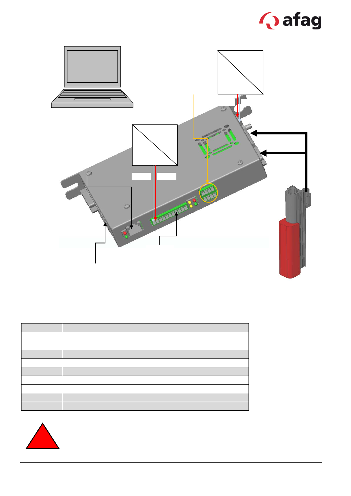
Connection
Description
X1 PWR+
Motor voltage supply +72 VDC
X1 PGND
Motor voltage supply GND
X2
Motorphasen
X3
Motor signals
X33
Safety relay (optional o n -S 1 vers ion)
X4.8
/Quickstop
X4.7
Reference sensor (optional)
X4.2
Logic power supply +24 VD C
X4.1
Logic power supply GND
!
2x RT Ethernet
safety relays
/Quickstop
mains
GND
+24VD
RS232
mains
PWR+
PGND
motor cable
external position
72 VDC
mains
24 VDC
mains
measuring system
(optional)
Danger when the safety door is open
The "safety relay" input (X33) on the controller C11xx must be deactivated or the power
pack (72 V) must be reliably disc onnected from the power supply on the primary side.
Subject to change. 19 Vers. 1. 1 en 01.01.2019
Afag Hardt GmbH – Gewerbestraße 11 - 78739 Hardt - Phone:07422/56003-0
Company headquarters: 78739 Hardt, Managing Director: Walter Kunz, HRB 480966 Stuttgart

Technical data
C1250-EC-XC
C1250-IP-XC
C1250-PL-XC
C1250-PN-XC
Logic power supply
24 VDC
24 VDC
24 VDC
24 VDC
Motor voltage supply
24 - 72 VDC
24 - 72 VDC
24 - 72 VDC
24 - 72 VDC
Max. output current motor
(at 72 V)
25 A
25 A
25 A
25 A
Bus system int erfaces
EtherCat
Master Encoder
Ethernet IP
Master Encoder
PowerLink
Master Encoder
Profinet
Master Encoder
Max. power consumption
30 W
30 W
30 W
30 W
Protection type
IP 20
IP 20
IP 20
IP 20
Operating temperature
0 - 40 °C
0 - 40 °C
0 - 40 °C
0 - 40 °C
Mass
0.7 kg
0.7 kg
0.7 kg
0.7 kg
Distance between
controllers
20 mm left/right
50 mm below/above
20 mm left/right
50 mm below/above
20 mm left/right
50 mm below/above
20 mm left/right
50 mm below/above
Fuse 72 V supply
16 AT
16 AT
16 AT
16 AT
Fuse 24 V supply
3 AT
3 AT
3 AT
3 AT Technical data
C1250-SC-XC
C1250-SE-XC
Logic power supply
24 VDC
24 VDC
Motor voltage supply
24 - 72 VDC
24 - 72 VDC
Max. output current motor
(at 72 V)
25 A
25 A
Bus system int erfaces
Sercos III
Master Encoder
Sercos over EtherCAT
Master Encoder
Max.
30 W
30 W
Protection type
IP 20
IP 20
Operating temperature
0 - 40 °C
0 - 40 °C
Mass
0.7 kg
0.7 kg
Distance between
controllers
20 mm left/right
50 mm below/above
20 mm left/right
50 mm below/above
Fuse 72 V supply
16 AT
16 AT
Fuse 24 V supply
3 AT
3 AT
Controller C12x0
Brief overview of the interfaces of the controller C12x0. More detailed information can be found in the
operating manual of the controller.
The controllers are preconfigured so that software modifications are generally not necessary.
modification is nec ess ary, the Li nMot-Talk 1100 so ftw are can be d ow nloaded free o f charg e from
the website www.linmot.com.
If a
CANopen
DeviceNet
RS485/232
Digitale I/Os
CANopen
DeviceNet
RS485/232
Digitale I/Os
CANopen
DeviceNet
RS485/232
Digitale I/Os
CANopen
DeviceNet
RS485/232
Digitale I/Os
CANopen
DeviceNet
RS485/232
Digitale I/Os
CANopen
DeviceNet
RS485/232
Digitale I/Os
Subject to change. 20 Vers. 1. 1 en 01.01.2019
Afag Hardt GmbH – Gewerbestraße 11 - 78739 Hardt - Phone:07422/56003-0
Company headquarters: 78739 Hardt, Managing Director: Walter Kunz, HRB 480966 Stuttgart

Connection
Description
X1 PWR+
Motor voltage supply +72 VDC
X1 PGND
Motor voltage supply GND
X2
Motor phases
X3
Motor signals
X33
Safety relay (optional on -S1 version)
X4.8
/Quickstop
X4.7
Reference sensor (optional)
X4.2
Logic power supply +24 VD C
X4.1
Logic power supply GND
!
mains
GND
+24VD
RS232
mains
PWR+
PGND
motor cable
RT Ethernet
RT Ethernet
safety relays
/Quickstop
72 VDC
mains
24 VDC
mains
Danger when the safety door is open
The "safety relay" input (X33) on the controller C12xx must be deactivated or the power
pack (72 V) must be reliably disc onnected from the power supply on the primary side.
Subject to change. 21 Vers. 1. 1 en 01.01.2019
Afag Hardt GmbH – Gewerbestraße 11 - 78739 Hardt - Phone:07422/56003-0
Company headquarters: 78739 Hardt, Managing Director: Walter Kunz, HRB 480966 Stuttgart

Technical data
E1230-DP-UC
E1250-EC-UC
E1250-PL-UC
E1250-SE-UC
Logic power supply
24 VDC
24 VDC
24 VDC
24 VDC
Motor voltage supply
24 - 72 VDC
24 - 72 VDC
24 - 72 VDC
24 - 72 VDC
Max. output current motor
Standard-Ausführung:
Standard-Ausführung:
Standard-Ausführung:
Standard-Ausführung:
Bus system int erfaces
Profibus
Master Encoder
EtherCat
Master Encoder
PowerLink
Master Encoder
Sercos over Ethercat
Master Encoder
Max. power consumption
30 W
30 W
30 W
30 W
Protection type
IP 20
IP 20
IP 20
IP 20
Operating temperature
0 - 40 °C
0 - 40 °C
0 - 40 °C
0 - 40 °C
Mass
1 kg
1 kg
1 kg
1 kg
Distance between
controllers
20 mm left/right
50 mm below/above
20 mm left/right
50 mm below/above
20 mm left/right
50 mm below/above
20 mm left/right
50 mm below/above
Fuse 72 V supply
20 AT
20 AT
20 AT
20 AT
Fuse 24 V supply
2 AT
2 AT
2 AT
2 AT Technical data
E1250-IP-UC
E1250-PN-UC
E1250-SC-UC
Logic power supply
24 VDC
24 VDC
24 VDC
Motor voltage supply
24 - 72 VDC
24 - 72 VDC
24 - 72 VDC
Max. output current motor
(at 72 V)
Standard-Ausführung:
32 A
Standard-Ausführung:
32 A
Standard-Ausführung:
32 A
Bus system int erfaces
Ethernet IP
Master Encoder
Profinet
Master Encoder
Sercos III
Master Encoder
Max. power consumption
30 W
30 W
30 W
Protection type
IP 20
IP 20
IP 20
Operating temperature
0 - 40 °C
0 - 40 °C
0 - 40 °C
Mass
1 kg
1 kg
1 kg
Distance between
controllers
20 mm left/right
50 mm below/above
20 mm left/right
50 mm below/above
20 mm left/right
50 mm below/above
Fuse 72 V supply
20 AT
20 AT
20 AT
Fuse 24 V supply
2 AT
2 AT
2 AT
Controller E12x0
Brief overview of the interfaces of the controller E12xx. More detailed information can be found in the
operating manual of the controller.
The controllers are preconfigured so that software modifications are generally not necessary.
modification is nec ess ary, the Li nMot-Talk 1100 so ftw are can be d ow nloaded free o f charg e from
the website www.linmot.com.
If a
(at 72 V)
32 A
CANopen
DeviceNet
RS485/232
Digitale I/Os
CANopen
DeviceNet
RS485/232
Digitale I/Os
32 A
CANopen
DeviceNet
RS485/232
Digitale I/Os
CANopen
DeviceNet
RS485/232
Digitale I/Os
32 A
CANopen
DeviceNet
RS485/232
Digitale I/Os
CANopen
DeviceNet
RS485/232
Digitale I/Os
32 A
CANopen
DeviceNet
RS485/232
Digitale I/Os
Subject to change. 22 Vers. 1. 1 en 01.01.2019
Afag Hardt GmbH – Gewerbestraße 11 - 78739 Hardt - Phone:07422/56003-0
Company headquarters: 78739 Hardt, Managing Director: Walter Kunz, HRB 480966 Stuttgart

Connection
Description
X1 PWR+
Motor voltage supply +72 VDC
X1 PGND
Motor voltage supply GND
X2
Motor phases
X3
Motor signals
X4.12
Safety Voltage Enable
X4.11
/Quickstop
X4.7
Reference sensor (optional)
X4.2
Logikspannungsversorgung +24 VDC
X4.1
Logic power supply GND
!
RS232
analogue
RT Ethernet Out
RT Ethernet In
mains
PWR+
PGND
mains
GND
+24VD
ID setting
of the controller
in hex
safety voltage
e
motor cable
/Quickstop
CANopen
RS485
Profibus DP
(nur E1130DP)
master
e
Ethernet
24 VDC
mains
72 VDC
mains
ncoder
nable
Danger when the safety door is open
For the controller E12xx, the power pack must be reliably disconnected from the power
supply on the primary side.
Subject to change. 23 Vers. 1. 1 en 01.01.2019
Afag Hardt GmbH – Gewerbestraße 11 - 78739 Hardt - Phone:07422/56003-0
Company headquarters: 78739 Hardt, Managing Director: Walter Kunz, HRB 480966 Stuttgart

Technical data
E1100-GP
E1130-DP
Logic power supply
24 VDC
24 VDC
Motor voltage supply
24 - 72 VDC
24 - 72 VDC
Max. output current motor (at 72 V)
Standard- Ausführung: 8 A
XC-Ausführung: 25 A
Standard- Ausführung: 8 A
XC-Ausführung: 25 A
Bussystem Schnittstellen
CANopen
9 digitale Ein-/Ausgänge
Profibus
Master Encoder
Max. power consumption
30 W
30 W
Protection type
IP 20
IP 20
Operating temperature
0 - 40 °C
0 - 40 °C
Mass
1 kg
1 kg
Distance between controllers
20 mm left/right
50 mm below/above
20 mm left/right
50 mm below/above
Fuse 72 V supply
10 AT (bei Standard-
16 AT (bei HC/XC-controller)
10 AT (bei Standard-
16 AT (bei HC/XC-controller)
Fuse 24 V supply
2 AT
2 AT
Controller E11x0
Brief overview of the interfaces of the controller E11xx. More detailed information can be found in the
operating manual of the controller.
The controllers are preconfigured so that software modifications are generally not necessary.
modification is nec ess ary, the Li nMot-Talk 1100 so ftw are can be d ow nloaded free o f charge from
the website www.linmot.com.
If a
HC-Ausführung: 15 A
DeviceNet
RS485/232
16 digitale Eingänge
8 digitale Ausgänge
controller)
HC-Ausführung: 15 A
CANopen
DeviceNet
RS485/232
Digitale I/Os
controller)
Subject to change. 24 Vers. 1. 1 en 01.01.2019
Afag Hardt GmbH – Gewerbestraße 11 - 78739 Hardt - Phone:07422/56003-0
Company headquarters: 78739 Hardt, Managing Director: Walter Kunz, HRB 480966 Stuttgart

Connection
Description
X1 PWR+
Motor voltage supply +72 VDC
X1 PGND
Motor voltage supply GND
X2
Motor phases (optional bei HC oder XC Reglern)
X3
Motor signals
X6
Digitale IO-Schnittst elle (nur E1100-GP, nicht im Bild)
X4.12
Safety Voltage Enable (! !! nicht bei E1100-GP !!!)
X4.11
/Quickstop
X4.7
Reference sensor (optional)
X4.2
Logic power supply +24 VD C
X4.1
Logic power supply GND
!
mains
PWR+
PGND
mains
GND
+24VD
RS232
ID setting
of the controller
Profibus DP
(nur E1130DP)
CANopen
RS485
master
e
motor cable
safety voltage
enable
(!!! not for
E1100
/Quickstop
72 VDC
mains
24 VDC
mains
in hex
ncoder
-GP !!!)
Gefahr bei geöffneter Schutztür
Beim Regler E11x0 muss das Leistungsnetzteil (72V) primärseitig sicher getrennt
werden.
Subject to change. 25 Vers. 1. 1 en 01.01.2019
Afag Hardt GmbH – Gewerbestraße 11 - 78739 Hardt - Phone:07422/56003-0
Company headquarters: 78739 Hardt, Managing Director: Walter Kunz, HRB 480966 Stuttgart

Technical data
B1100-PP
B1100-GP
Logic power supply
24 VDC
24 VDC
Motor voltage supply
24 - 72 VDC
24 - 72 VDC
Max. output current motor (at 72 V)
Standard- Ausführung: 8 A
XC-Ausführung: 25 A
Standard- Ausführung: 8 A
XC-Ausführung: 25 A
Bussystem Schnittstellen
6 digitale Eingänge
CANopen
6 digitale Ausgänge
Max. power c onsumption
30 W
30 W
Protection type
IP 20
IP 20
Operating temperature
0 - 40 °C
0 - 40 °C
Mass
0.7 kg
0.7 kg
Distance between controllers
20 mm left/right
50 mm below/above
20 mm left/right
50 mm below/above
Fuse 72 V supply
10 AT (bei Standard-
10 AT (bei Standard-
Fuse 24 V supply
2 AT
2 AT
Controller B1100
Brief overview of the interfaces of the controller B1100. More detailed information can be found in the
operating manual of the controller.
The controllers are preconfigured so that software modifications are generally not necessary.
modification is nec ess ary, the Li nMot-Talk 1100 so ftw are can be d ow nloaded free o f charg e from
the website www.linmot.com.
If a
HC-Ausführung: 15 A
6 digitale Ausgänge
(bis zu 4 Positionen)
controller)
16 AT (bei HC/XC-controller)
HC-Ausführung: 15 A
DeviceNet
RS485/232
6 digitale Eingänge
controller)
16 AT (bei HC/XC-controller)
Subject to change. 26 Vers. 1. 1 en 01.01.2019
Afag Hardt GmbH – Gewerbestraße 11 - 78739 Hardt - Phone:07422/56003-0
Company headquarters: 78739 Hardt, Managing Director: Walter Kunz, HRB 480966 Stuttgart

Connection
Description
X1 PWR+
Motor voltage supply +72 VDC
X1 PGND
Motor voltage supply GND
X2
Motor phases (optional bei HC oder XC Reglern)
X3
Motor signals
X14.14
/Quickstop
X14.2
Reference sensor (optional)
X14.25
Logic power supply +24 VDC
X14.13
Logic power supply GND
!
RS232
CANopen
RS485
24VD
+24VDC
GND
/Quickstop
motor cable
PWR+
PGND
mains
72 VDC
mains
24 VDC
mains
Danger when the safety door is open
For the controller B1100, the power pack (72V) must be reliably disconnected from the
power supply on the primary side.
Subject to change. 27 Vers. 1. 1 en 01.01.2019
Afag Hardt GmbH – Gewerbestraße 11 - 78739 Hardt - Phone:07422/56003-0
Company headquarters: 78739 Hardt, Managing Director: Walter Kunz, HRB 480966 Stuttgart

Connector combinations
Connector on the axis
Connector on the controller
R connector:
D connector:
C connector:
W connector:
Motor conne c t or
Application:
Application:
- Electro slides ES20
- Portal axis PEL20
- Rotary axis SE20
- Electro slides ES30
- Portal axis PEL30
- Portal axis PDL30
- Portal axis PDL40
- Portal axis PDL40-HC
- Rotary axis SE30
Application:
- Controller B1100 standard
- Controller E11xx standard
Application:
- Controller B1100 standard, HC u nd XC
- Controller E11xx standard, HC und XC
- Controller E12xx UC
Y connector:
Application:
- Controller C11xx XC
- Controller C12xx XC
Subject to change. 28 Vers. 1. 1 en 01.01.2019
Afag Hardt GmbH – Gewerbestraße 11 - 78739 Hardt - Phone:07422/56003-0
Company headquarters: 78739 Hardt, Managing Director: Walter Kunz, HRB 480966 Stuttgart
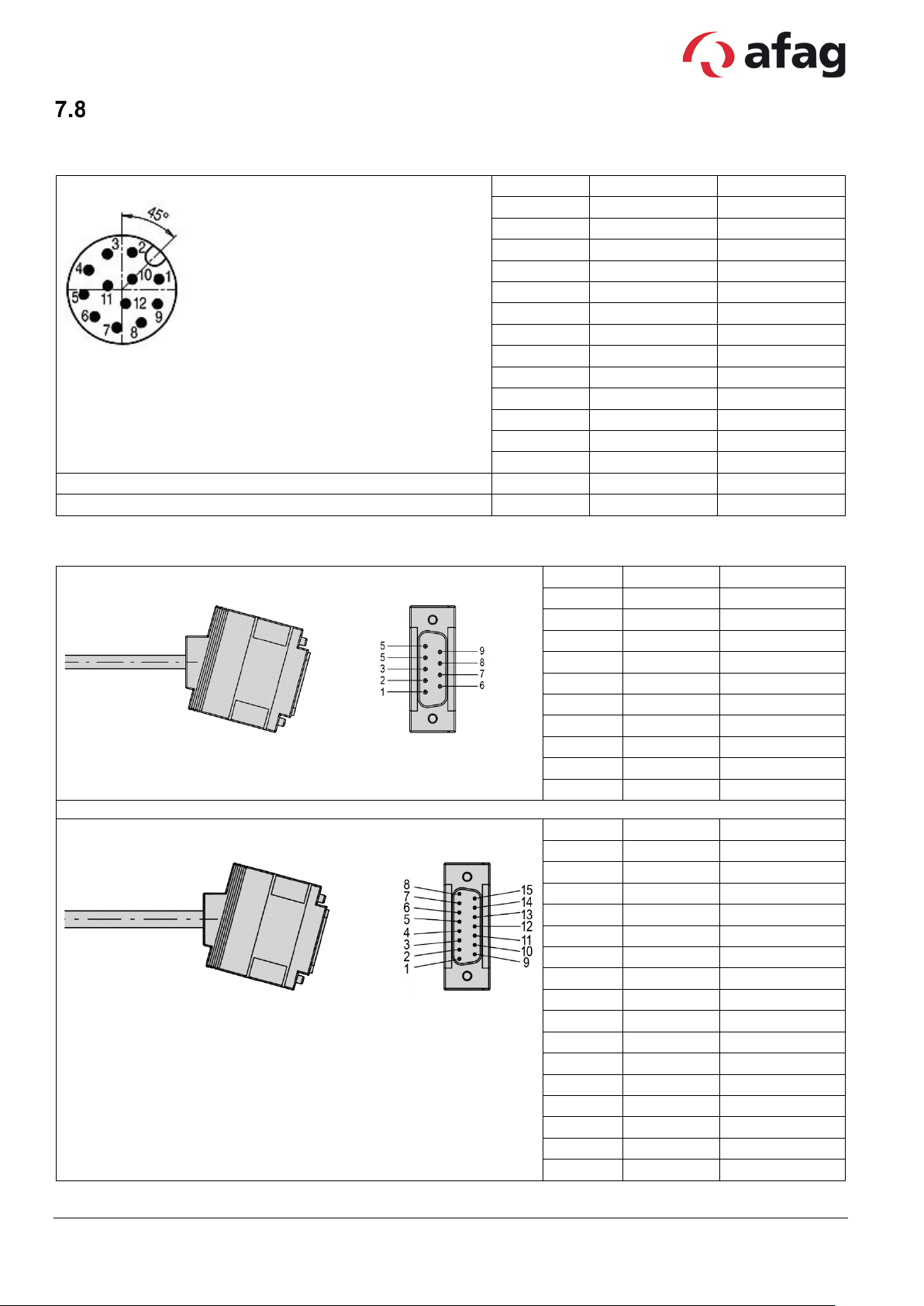
Cable connector S713 12pole M12x1
PIN
Function
Cable
1
open
-
2
Z+
grey 10
3
Z-
grey 9
4
open
-
5
+5V
grey 2
6
A-
grey 5
7
A+
grey 6
8
B-
grey 7
9
B+
grey 8
10
open
-
11
open
-
12
GND
grey 3
housing
screen
screen
NC
red 1
NC
grey4
Controller E11xx line
PIN
Function
Cable
1
+5 V
pink
2
A- / sin-
yellow
3
B- / cos-
grey
4
Z-
white
5
GND
red/blue
6
A+ / sin+
black
7
B+ / cos+
red
8
Z+
blue
9
open
-
housing
screen
screen
Controller C1xx0, B1100 und E12x0 line
PIN
Function
Cable
1
+5 V
pink
2
A- / sin-
yellow
3
B- / cos-
grey
4
Z- / Data -
white
5
GND
red/blue+purple
6
open
-
7
open
-
8
Clock-
green
9
A+ / sin+
black
10
B+ / cos+
red
11
Z+ / Data+
blue
12
open
-
13
open
-
14
open
-
15
Clock+
grey/pink
housing
screen
screen
Plug c onfi guration encoder
7.8.1 Round connector on the module
7.8.2 Encoder plug configuration on the controller
Subject to change. 29 Vers. 1. 1 en 01.01.2019
Afag Hardt GmbH – Gewerbestraße 11 - 78739 Hardt - Phone:07422/56003-0
Company headquarters: 78739 Hardt, Managing Director: Walter Kunz, HRB 480966 Stuttgart
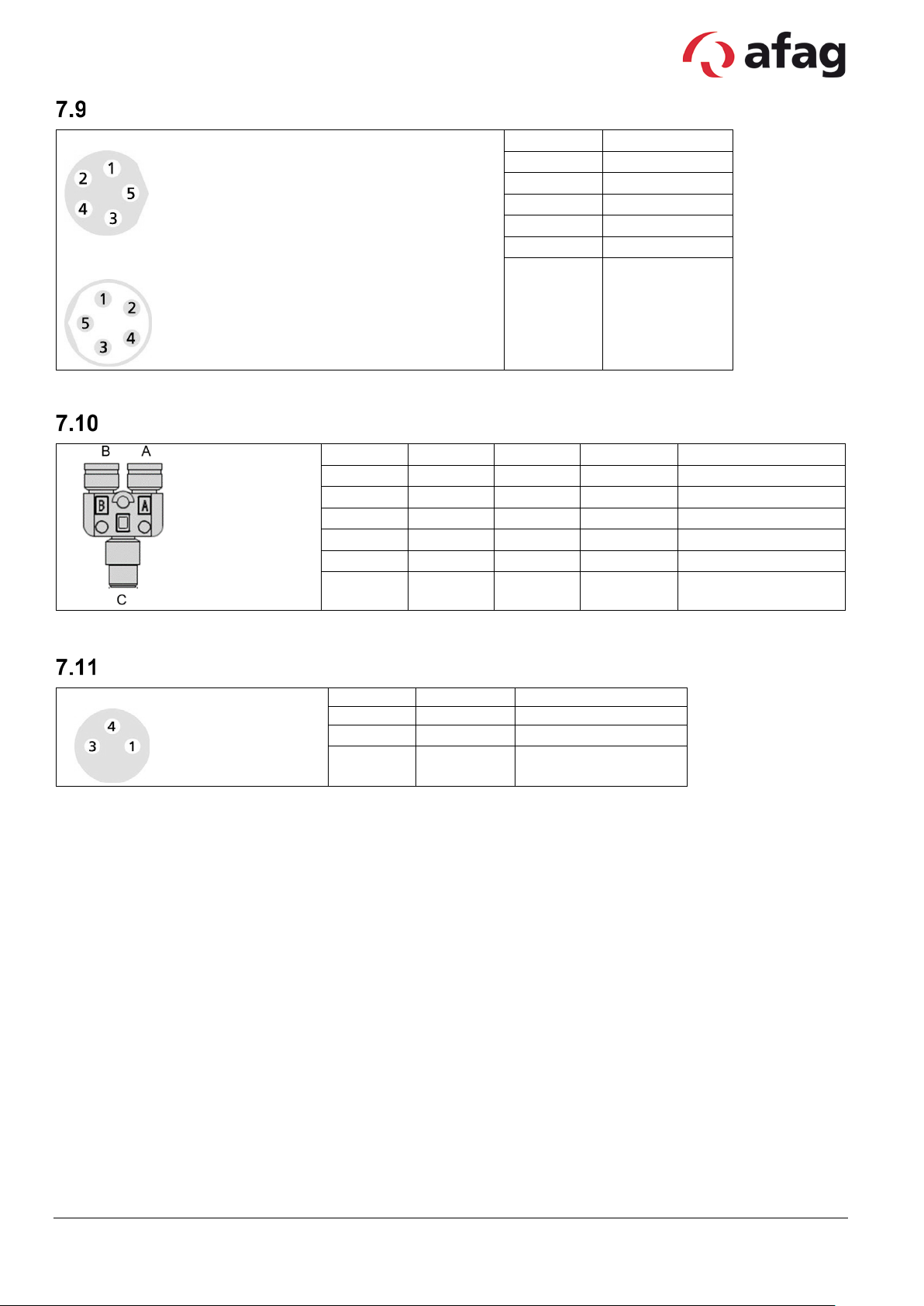
Socket 5pole M8x1
PIN
Cable
1
brown
2
white
3
blue
4
black
5
grey
housing
screen
PIN C
PIN A
PIN B
Function
Cable
1 1 1
24VDC
brown
2 4 -
Signal A
white
3 3 3
GND
blue
4 - 4
Signal B
black
5 - -
NC
grey
housing
screen
Connector 3pole M8x1
PIN A
Function
Cable
1
24VDC
brown
4
Signal
white
3
GND
blue
Electrical feed-through / Proximity sw itch cable-R11
Connector 5pole M8x1
Y-di s t ributor plug R12
Reference sensor
Subject to change. 30 Vers. 1. 1 en 01.01.2019
Afag Hardt GmbH – Gewerbestraße 11 - 78739 Hardt - Phone:07422/56003-0
Company headquarters: 78739 Hardt, Managing Director: Walter Kunz, HRB 480966 Stuttgart

Max.
[m/s]
Max.
[m/s2]
Max.
[m/s2]
Std
[m/s]
Std
[m/s2]
Std
[m/s2]
Max.
[mm]
Max
[mm]
RA-40-x-50-x
0.84
30
30
0.84
20
20 ∞ ∞
RA-40-x-30-x
1.7
20
20
1.7
15
15 ∞ ∞
!
!
8 6 Commissioning
All information in the operating manuals of the individual modules must also be
observed.
Setting speeds of the electric axes
The speeds of the electric axes are generally set by the higher-ranking controller.
Example programs are availa bl e for a large number of comm on controllers. This allows the
maximum speed, accelerat ion and target position to be set.
CD provided upon delivery, or you can download them at
https://www.afag.com/de/service/support-tools/linmot.html.
These travel profiles ar e s tored in the controller when using the B1100-PP or E1100-GP controller
with EasyStep firm ware.
Caution
An excessively high speed or acceleration can cause damage to the device or the
periphery.
The following tables are intended as references for t he par ameters (speed, acceleration,
deceleration).
Please note that you do not have to adapt the standard parameters for your application.
They are heavily dependent on the load mass and the mechanical configuration.
These programs are available on the
Overview electrical axes
Type
Subject to change. 31 Vers. 1. 1 en 01.01.2019
Afag Hardt GmbH – Gewerbestraße 11 - 78739 Hardt - Phone:07422/56003-0
Company headquarters: 78739 Hardt, Managing Director: Walter Kunz, HRB 480966 Stuttgart
speed
accel.
decel.
speed
accel.
decel.
Pos.
Pos.

!
Teaching of pos itions on electric axes
The drive must be referenced first. Then you have the following possibilities:
Possibility 1 – move manually:
Move the axes into position by h and ( l ogic voltage ON, motor power OFF) and then read out values
from the controller for use in the Pick&Place movement.
Danger
For the controller B1100 or E1xxx, the power pack (72 V) must be reliably disconnected
from the power supply on the pr imary side.
With controller C1xx0 the "safety inputs" input (X33) must be deactivated or the
power pack (72 V) reliably disconnected on the primary side.
Possibility 2 – jog mode:
• Add value to or subtract value from current position
• Can be programmed with relat ive commands.
The existing module for absolute positioning can be convert ed i nto one for relative
positioning by changing one variable.
Possibility 3:
Set-up with safely reduced s peed. Please observe the manual on the safely reduced speed.
1.1 Switching distance
1.1.1 Reference sensor with electric axes
The sensor is installed parallel to the switching flag at a distance of 0.1 mm using a feeler
gauge.
Subject to change. 32 Vers. 1. 1 en 01.01.2019
Afag Hardt GmbH – Gewerbestraße 11 - 78739 Hardt - Phone:07422/56003-0
Company headquarters: 78739 Hardt, Managing Director: Walter Kunz, HRB 480966 Stuttgart

!
!
9 Maintenance
The EPS devices are high-performance devices with very short c ycle times. The service life of the
devices depends to a very great extent on the ambient conditions and the maintenance.
Therefore, the maintenance instructions for the individ ual modules must always be
followed.
The service and maintenance int ervals must be observed. The int er vals are based on a normal
environment. The approval of Afag Hardt GmbH must be obtained in advance if the devices are to
be operated in an environm ent with abrasive dusts or with corros ive or aggressive vapours, ga ses
or liquids.
10 Repairs
Repairs may only be carried out by Afag Hardt GmbH.
If you carry out the repair yourself, approval must be obtained in a dvance from eps GmbH.
Caution
Repairs may only be carried out by q ualified personnel.
Subject to change. 33 Vers. 1. 1 en 01.01.2019
Afag Hardt GmbH – Gewerbestraße 11 - 78739 Hardt - Phone:07422/56003-0
Company headquarters: 78739 Hardt, Managing Director: Walter Kunz, HRB 480966 Stuttgart

Designation
Module/axis
Controller
Application
dynamic
roboter
Motor cableM21-8m-0-0-X
Motor cable-
Motor cable-
Motor cable-
Motor cable-
Motor cableM20-8m-0-2-2
Motor cableM16-8m-0-1-X
Motor cableM16-8m-0-1-1
Motor cableM16-8m-0-1-2
Motor cableM24-8m-0-2-X
Motor cableM22-8m-0-2-1
Motor cableM22-8m-0-2-2
Motor cable-
Motor cable-
Motor cable-
Motor cable
M16-8m-0-0-1
Motor cable
M16-8m-0-0-2
11 Component/replacement part lists
The replacement parts for the standard components are listed here. The ord er numb ers on our
delivery note are applicable to special components.
Overview motor cabel-designation-axes-controller-application
Designation
of producer
K05-D/R-8
KS05-D/R-8
KR05-D/R-8
K05-W/R-8
KS05-W/R-8
KR05-W/R-8
K05-Y/R-8
KS05-Y/R-8
KR05-Y/R-8
Designation
<->
<->
M21-8m-0-0-1
<->
M21-8m-0-0-2
<->
M20-8m-0-2-X
<->
M20-8m-0-2-1
<->
<->
<->
<->
of afag
ES20 SE20
ES30
RA-40
PEL20
SE30
PxL30
PxL40
C1xxx
B1100
PxL40-HP
E12xx
E11x0
installation
static installation
x x x x x X
x
x x x x x x x X
x x x x x x x x X
x x x x x x x X
x x x x x x x x X
x x x x x x x x x X
x x x x x X
x x x x x x X
x x x x x x x X
installation
K15-W/C-8
KS10-W/C-8
KR10-W/C-8
K15-Y/C-8
KS10-Y/C-8
KR10-Y/C-8
KS05-R/R-8
KR05-R/R-8
Note: X = preferred option; x = application possible
Subject to change. 34 Vers. 1. 1 en 01.01.2019
Afag Hardt GmbH – Gewerbestraße 11 - 78739 Hardt - Phone:07422/56003-0
Company headquarters: 78739 Hardt, Managing Director: Walter Kunz, HRB 480966 Stuttgart
<->
<->
<->
<->
M23-8m-0-1-X
<->
M17-8m-0-1-1
<->
M17-8m-0-1-2
<->
extension-
<->
extension-
x x x x x x x x X
x x x x x x x x x X
x x x x x x x x x x X
x x x x x x X
x x x x x x x X
x x x x x x x x X
x x x x x x x x X X
x x x x x x x x x x X

Designation
Module/axis
Controller
Application
dynamic
roboter
Motor cable
M23-8m-0-0-X
Motor cable
M17-8m-0-0-1
Motor cable
M17-8m-0-0-2
Designation
Art. no.
Motor cable-M16-4m-0-1-X
50463073
Motor cable-M16-6m-0-1-X
50463076
Motor cable-M16-8m-0-1-X
50463078
Motor cable-M16-4m-0-1-1
50437168
Motor cable-M16-6m-0-1-1
50437167
Motor cable-M16-8m-0-1-1
50427023
Extension-M16-2m-0-0-1
50450944
Extension-M16-4m-0-0-1
50427026
Extension-M16-6m-0-0-1
50463082
Extension-M16-2m-0-0-2
50463081
Motor cable-M17-4m-0-1-1
50437170
Motor cable-M17-6m-0-1-1
50437169
Motor cable-M17-8m-0-1-1
50427021
Extension-M17-2m-0-0-1
50463084
Extension-M17-4m-0-0-1
50427024
Extension-M17-6m-0-0-1
50463087
Extension-M17-2m-0-0-2
50463085
Extension-M17-4m-0-0-2
50463086
Motor cable-M20-4m-0-2-X
50463088
Motor cable-M20-6m-0-2-X
50463090
Motor cable-M20-8m-0-2-X
50463092
Motor cable-M20-4m-0-2-1
50463089
Motor cable-M20-6m-0-2-1
50463091
Motor cable-M20-8m-0-2-1
50463093
Designation
Art. no.
Motor cable-M21-4m-0-0-X
50463094
Motor cable-M21-6m-0-0-X
50463096
Motor cable-M21-8m-0-0-X
50463098
Motor cable-M21-4m-0-0-1
50463095
Motor cable-M21-6m-0-0-1
50463097
Motor cable-M21-8m-0-0-1
50463099
Motor cable-M22-4m-0-2-1
50463100
Motor cable-M22-6m-0-2-1
50463101
Motor cable-M22-8m-0-2-1
50463103
Motor cable-M23-4m-0-1-X
50463104
Motor cable-M23-6m-0-1-X
50463105
Motor cable-M23-8m-0-1-X
50463106
Motor cable-M24-4m-0-2-X
50463107
Motor cable-M24-6m-0-2-X
50463108
Motor cable-M24-8m-0-2-X
50463109
Designation
of producer
K15-C/C-8
KS10-C/C-8
KR10-C/C-8
Note: X = preferred opt ion; x = application possible
<->
<->
<->
extension-
extension-
extension-
Designation
of Afag
ES20 SE20
x x x x x x x x x X
x x x x x x x x x x X
x x x x x x x x x x x X
Motor c a ble
installation
ES30
RA-40
PEL20
SE30
PxL30
PxL40
C1xxx
PxL40-HP
E11xx
B1100
E12xx
static installation
installation
Subject to change. 35 Vers. 1. 1 en 01.01.2019
Afag Hardt GmbH – Gewerbestraße 11 - 78739 Hardt - Phone:07422/56003-0
Company headquarters: 78739 Hardt, Managing Director: Walter Kunz, HRB 480966 Stuttgart

Bezeichnung
Art. Nr.
Encoder cable-G18-10m-0-0-1
50468310
Encoder cable-G18-10m-90-0-1
50468311
Extension-G18-2m-0-0-1
50468312
Extension-G18-5m-0-0-1
50468313
Encoder cable -G19-10m-0-0-1
50468314
Encoder cable -G19-10m-90-0-1
50468315
Designation
Art. no.
Controller B1100-GP
für CANopen, RS485, Digital IO
Controller B1100-GP-HC
für CANopen, RS485, Digital IO
16080027
Controller B1100-GP-XC
für CANopen, RS485, Digital IO
16080230
Controller B1100-PP
für Digital IO
16080231
Controller B1100-PP-HC
für Digital IO
16080232
Controller B1100-PP-XC
für Digital IO
16080233
Controller E1100-GP
für CANopen, RS 485, Digital IO
50465788
Controller E1100-GP-HC
für CANopen, RS 485, Digital IO
50465790
Controller E1100-GP-XC
für CANopen, RS 485, Digital IO
50465791
Controller E1100-RS
für RS485
16080016
Controller E1100-RS-HC
für RS485
16080014
Controller E1100-RS-XC
für RS485
16080234
Controller E1130-DP
für Profibus DP
50465761
Controller E1130-DP-HC
für Profibus DP
16080021
Controller E1130-DP-XC
für Profibus DP
Controller E1250-EC
für EtherCAT
16080243
Controller E1250-PL
für PowerLink
50465787
Controller C1250-SE-XC-1S
für Sercos over EtherCAT
Controller C1250-SC-XC-1S
für Sercos III
16080417
Controller C1250-PN-XC-1S
für Profinet
16080415
Controller C1250-PL-XC-1S
für PowerLink
Controller C1250-PD-XC-1S
für Profidrivet
16080763
Controller C1250-LU-XC-1S
für LinUDP
16080741
Controller C1250-IP-XC-1S
für Ethernet IP
16080411
Controller C1250-EC-XC-1S
für EtherCat
16080405
Controller C1200-GP-XC-1S
für General Purpose
16080407
Controller C1150-SE-XC-1S
für Sercos over EtherCAT
16080768
Controller C1150-PN-XC-1S
für Profinet
16080429
Controller C1150-EC-XC-1S
für EtherCat
16080434
Controller C1100-GP-XC-1S
für CANopen
16080432
Encoder
Controller
16080221
50465786
16080409
16080413
Subject to change. 36 Vers. 1. 1 en 01.01.2019
Afag Hardt GmbH – Gewerbestraße 11 - 78739 Hardt - Phone:07422/56003-0
Company headquarters: 78739 Hardt, Managing Director: Walter Kunz, HRB 480966 Stuttgart

12 Disposal instructions
Products
• Products that are predominantly made out of metal (axes, modules, adaptor plates etc.)
must be disposed of in accordance with the national laws of metal recycling.
• Electronic products (controllers, etc.) must be disposed of in accordance with the national
laws of electronic scrap.
Packaging
Cardboard, paper or PE film are predominantly used as packaging material.
These are materials that can be used in global recycling processes.
If the packaging is returned to us free domicile, Afag Hardt will take it back for free and dispose
of it accordingly.
Subject to change. 37 Vers. 1. 1 en 01.01.2019
Afag Hardt GmbH – Gewerbestraße 11 - 78739 Hardt - Phone:07422/56003-0
Company headquarters: 78739 Hardt, Managing Director: Walter Kunz, HRB 480966 Stuttgart

Installation manual
the following conditions m ust be satisfied so that it can be assembled together with other parts to
Ins tallation may only be carried out by q ualified specialist personnel.
13 Installation manual in accordance with Appendix VI (EC-RL
2006/42/EC)
in accordance with Appendix VI
(EC-RL 2006/42/EC)
For the installation of the partly completed
machinery
form a complete machine cor rectly and without endangering the health and safety of persons:
Please observe the safety information in the risk assessment
Read, understand and observe the whole operating manual
RA-40
Subject to change. 38 Vers. 1. 1 en 01.01.2019
Afag Hardt GmbH – Gewerbestraße 11 - 78739 Hardt - Phone:07422/56003-0
Company headquarters: 78739 Hardt, Managing Director: Walter Kunz, HRB 480966 Stuttgart

Installation declaration
meet the following basic r equi r ements of the machinery directi ve 2006/42/EC:
isions of the electrical equipment
The manufacturer commits to electronically submitting these special documents to individual state
14 Installation declaration for partly completed machinery (EC-RL
2006/42/EC)
for partly completed machinery
(EC-RL 2006/42/EC)
The manufacturer:
Afag Hardt GmbH
Gewerbestraße 11
D-78739 Hardt
hereby declares that the following products
RA-40
Appendix I, Article 1.1.2, 1.1.3, 1.1.5, 1.3.2, 1.3.4 and 1.5.1.
The partly completed machinery also corresponds to all prov
(2014/35/EU) and electromagnetic compatibility (2014/30/EU) directives.
The incomplete machine must only be put into operation when it has been f ound that the machine into
which the incomplete machine is to be installed corresponds to the provisions of the machinery directive
2006/42/EC.
offices upon request.
The technical document ation for this machine was dra wn up accor ding to Appendix VII, par t B
Name of the authorised representative: Walter Kunz
Address of the authorised representative: Gewerbest r aße 11 - 78739 Hardt
Subject to change. 39 Vers. 1. 1 en 01.01.2019
Afag Hardt GmbH – Gewerbestraße 11 - 78739 Hardt - Phone:07422/56003-0
Company headquarters: 78739 Hardt, Managing Director: Walter Kunz, HRB 480966 Stuttgart

Procedures used
Angewan
15 Risk assessment (EG-RL 2006/42/EG)
for the risk assessment
Diagram utilised for general risk assessment in accordance with ISO/TR 1412-2:
Diagram utilised in accordance with EN 13849 for the determination of the required performance level
(PL):
Subject to change. 40 Vers. 1. 1 en 01.01.2019
Afag Hardt GmbH – Gewerbestraße 11 - 78739 Hardt - Phone:07422/56003-0
Company headquarters: 78739 Hardt, Managing Director: Walter Kunz, HRB 480966 Stuttgart

Determination of the machine limitations
1.
Limits of use
Installation and equipping of various components, products
Application area of the machine
Yes
Industry
Yes
No
User groups
Function
Qualification/impairments
Maintenance,
Operation
trained
Operators
Operation
experienced/trained
2.
Spatial limits
Machine/system description
Energy supply interfaces
3.
Time limits
10 years
Recommended maintenance intervals
Maintenance
4.
Additional limits
0 – 50 °C
Required degree of cleanli ness
No special requirements
Materials and properties o f processed
Intended use
Business
Household
Qualified personnel
Apprentices
commissioning
Operation
Specialist training
Intended application duration
Highest/lowest ambient temperatures
materials
See system description
Electrical energy suppl y
Pneumatic energy supply
See
No special requirements
Subject to change. 41 Vers. 1. 1 en 01.01.2019
Afag Hardt GmbH – Gewerbestraße 11 - 78739 Hardt - Phone:07422/56003-0
Company headquarters: 78739 Hardt, Managing Director: Walter Kunz, HRB 480966 Stuttgart

Identification of hazards
Risk
assessment
Persons who wear
Pos. Life phases Description of hazard
Hazard due to improper
1 Transport
transportation of
machine
Electrical hazard. Direct
2
Operation,
Maintenance
Repairs
or indirect contact with
energised parts when
errors occur on electrical
components.
S = S2
F = F1
O = O1
A = A1
Erg = 3
S = S2
F = F1
O = O1
A = A1
Erg = 3
Measures to reduce risk PL
Observe the total
weight and correct
transportation m ethods
--
in the operating manual.
1.
Electrical equipment
designed in accordance
with EN 60204.
2.
Installation and
maintenance of
electrical equipm ent
must only be carried out
by specialist personnel.
S = S2
F = F1
P = P1
PL = c
3.
Maintenance and repair
work must only be
carried out in a voltagefree and compressed
air-free state.
3
Maintenance
Repairs
Subject to change. 42 Vers. 1. 1 en 01.01.2019
Afag Hardt GmbH – Gewerbestraße 11 - 78739 Hardt - Phone:07422/56003-0
Company headquarters: 78739 Hardt, Managing Director: Walter Kunz, HRB 480966 Stuttgart
pacemakers must
maintain a safety
Pacemakers may be
affected by permanent
magnets.
S = S2
F = F1
O = O1
A = A1
Erg = 3
distance of a minimum
of 0.2 m from the
module.
The device is equipped
with corresponding
warning signs.
--
The personnel must be
instructed accordingly.

Risk
assessment
Risks of limb crushing,
Pos. Life phases Description of hazard
Pacemakers may be
4 Operation
affected by permanent
magnets.
bruising and broken
5 Operation
bones due to accessing
the travel range of the
moving device.
Burning of the skin due
to surface temperat ures
of up to 60°C.
6
Operation,
Maintenance
Repairs
S = S2
F = F1
O = O1
A = A1
Erg = 3
S = S2
F = F2
O = O2
A = A1
Erg = 4
S = S1
F = F1
O = O2
A = A1
Erg = 1
Measures to reduce risk PL
With the safeguard, a
safety distance of
0.2 m from the
--
pacemaker must be
guaranteed
Operation of the device
behind a
safeguard to ensure
that access to the
travel range is denied.
S = S2
F = F1
P = P1
PL = c
1.
Avoid direct contact
when the device is in
operation.
2.
Allow the device to cool
--
down before carrying
out maintenance work,
or protect the skin
accordingly (gloves,
long clothing...)
Subject to change. 43 Vers. 1. 1 en 01.01.2019
Afag Hardt GmbH – Gewerbestraße 11 - 78739 Hardt - Phone:07422/56003-0
Company headquarters: 78739 Hardt, Managing Director: Walter Kunz, HRB 480966 Stuttgart

Risk
assessment
be reliably disconnected
Pos. Life phases Description of hazard
7
Maintenance,
commissioning
Risks of limb crushing,
bruising and broken
bones due to accessing
the travel range of the
device when the
protective door is open.
S = S2
F = F2
O = O2
A = A1
Erg = 4
Measures to reduce risk PL
1.
The pressurised air
supply must be reliably
disconnected.
2.
The "safety relay" input
(X33) on the controller
C1xxx must be
deactivated or the
power pack (72 V) must
from the power supply
on the primary side.
3.
The power pack (72 V)
must be reliably
disconnected from the
power on the primary
side when using the
B1100, E12xx or E1xxx
S = S2
F = F1
P = P1
PL = c
controllers.
4.
For linear motor axes
(excluding ES40, ES40HP, PDL40 and PDL40HP) through secure
monitoring of the
reduced speed!!!
Observe the special
documentation!!!
Furthermore, specialist
personnel must check
that all components
have been properly
installed and ensure
that there is no
manipulation.
Subject to change. 44 Vers. 1. 1 en 01.01.2019
Afag Hardt GmbH – Gewerbestraße 11 - 78739 Hardt - Phone:07422/56003-0
Company headquarters: 78739 Hardt, Managing Director: Walter Kunz, HRB 480966 Stuttgart

16 Support
Afag Hardt GmbH
Gewerbestraße 11
D-78739 Hardt
T +49 (0)7422/56003-20
E-Mail: support.hardt@afag.com
Internet: www.afag.com
Subject to change. 45 Vers. 1. 1 en 01.01.2019
Afag Hardt GmbH – Gewerbestraße 11 - 78739 Hardt - Phone:07422/56003-0
Company headquarters: 78739 Hardt, Managing Director: Walter Kunz, HRB 480966 Stuttgart

17 Notes
Subject to change. 46 Vers. 1. 1 en 01.01.2019
Afag Hardt GmbH – Gewerbestraße 11 - 78739 Hardt - Phone:07422/56003-0
Company headquarters: 78739 Hardt, Managing Director: Walter Kunz, HRB 480966 Stuttgart

Afag Hardt GmbH
Gewerbestraße 11
D-78739 Hardt
T +49 (0)7422/56003-0
F +49 (0)7422/56003-29
E-Mail: sales@afag.com
Internet: www.afag.com
Subject to change. 47 Vers. 1. 1 en 01.01.2019
Afag Hardt GmbH – Gewerbestraße 11 - 78739 Hardt - Phone:07422/56003-0
Company headquarters: 78739 Hardt, Managing Director: Walter Kunz, HRB 480966 Stuttgart
 Loading...