

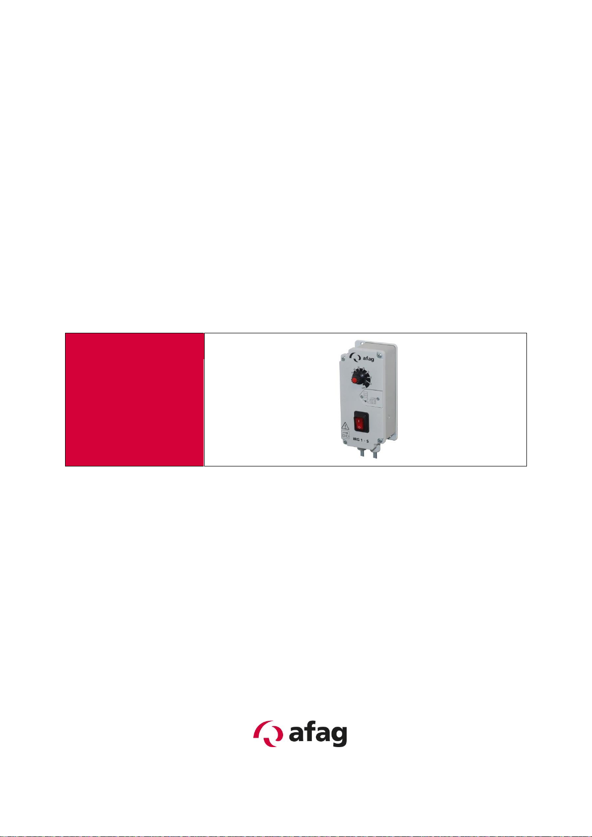
Controller
IRG 1-S
Translation of operating and installation instructions
Copyright by Afag GmbH

Type
Order number
Controller IRG 1-S
230 V / 50 Hz
50360105
115 V / 60 Hz
50360106
This operation instruction applies to:
Version of Documentation: BA_IRG1-S_R02.0_EN.docx
Release: R02.0
Date: 7/31/2017
Effective from: A-492295
Page 2 7/31/2017 R02.0

Table of contents:
1 Safety instructions ............................................................................................ 4
1.1 Notes on symbols and instructions ........................................................................................................ 4
1.2 Basic safety information ........................................................................................................................ 5
1.3 Specified use .......................................................................................................................................... 5
2 Description of the device .................................................................................. 6
2.1 General .................................................................................................................................................. 6
2.2 Technical data ....................................................................................................................................... 7
3 Assembly instructions ...................................................................................... 9
3.1 Installing the unit ................................................................................................................................... 9
3.2 Connection possibilities ......................................................................................................................... 9
4 Operating instructions .................................................................................... 10
4.1 Internal Trimmers ................................................................................................................................ 11
4.2 Setpoint source .................................................................................................................................... 11
4.3 Half- and full wave ............................................................................................................................... 11
4.4 Soft start .............................................................................................................................................. 11
4.5 Invert enable: ....................................................................................................................................... 11
5 Maintenance instructions ................................ ................................ ............... 11
5.1 Replacing the fuse ............................................................................................................................... 11
5.2 Troubleshooting and fault repair ......................................................................................................... 12
6 Accessories ..................................................................................................... 12
6.1 Fixture .................................................................................................................................................. 12
6.2 Address for orders................................................................................................................................ 13
7 Disposal ........................................................................................................... 13
R02.0 7/31/2017 Page 3
DANGER
Indicates an immediate threatening danger.
Non-compliance with this information can result in death or seri-
ous personal injuries (invalidity).
WARNING
Indicates a possible dangerous situation.
Non-compliance with this information can result in death or seri-
ous personal injuries (invalidity).
CAUTION
Indicates a possibly dangerous situation.
Non-compliance with this information can result in damage to
property or light to medium personal injuries.
NOTE
Indicates general notes, useful operator tips and operating recommendations which don’t affect safety and health of the personnel.
1 Safety instructions
1.1 Notes on symbols and instructions
Symbols: Assembly and commissioning must be carried out by qualified per-
sonnel only and according to these operating instructions.
Please observe the meaning of the following symbols and notes. They are grouped
into risk levels and classified according to ISO 3864-2.
Page 4 7/31/2017 R02.0

1.2 Basic safety information
DANGER
Hazardous Voltage! Failure to observe can kill, cause serious injury or damage.
NOTE
Any other use is inappropriate and will result in the warranty becoming null and void.
This description contains the necessary information for the correct application of the
product described below. It is intended for use by technically qualified personnel.
Qualified personnel are persons who, because of their training, experience and position as well as their knowledge of appropriate standards, regulations, health and
safety requirements and working conditions, are authorised to be responsible for the
safety of the equipment, at all times, whilst carrying out their normal duties and are
therefore aware of, and can report, possible hazards (Definition of qualified employees according to IEC 364).
Isolate from mains before installation or dismantling work, as well as for fuse
changes or post installation modifications.
Observe the prescribed accident prevention and safety rules for the specific
application.
Before putting into operation check if the rated voltage for the unit conforms
with the local supply voltage.
Emergency stop devices must be provided for all applications. Operation of
the emergency stop must inhibit any further uncontrolled operation.
Electrical connections must be covered.
The earth connection must be checked for correct function, after installation.
1.3 Specified use
The units described herein are electrical controllers for installation in industrial plants.
They are designed for power adjustment on vibratory feed equipment.
See also our General Terms of Business.
R02.0 7/31/2017 Page 5

NOTE
Miniature magnets can also be operated safely at the IRG 1-S controller!
CAUTION
In the case of applications that require the oscillation conveyor to
be switched ON and OFF constantly (e.g. dust switching, hopper
control system, etc.), the prescribed controller input must be
used. If the load circuit is disconnected with a switch or a relay
the controller may be damaged.
If the controller is switched on, never insert or remove the plug at
the vibration conveyor being operated. This can damage the appliance.
2 Description of the device
2.1 General
Electronic controller IRG1-S for the infinitely variable regulation of magnetically driven
vibratory bowl, linear or hopper feeders.
The units operate using the phase-angle control principle to provide a variable output
voltage for the drive magnet. Feeder throughput is adjusted with a potentiometer fitted in the front plate. The control range of the potentiometer can be scaled by using
internal trimmers U
ler can be used with vibratory feeders that have a tuned frequency of 6000 vibs/min
(7200 vibs/min) or 3000 vibs/min (3600 vibs/min) (also referred to as full and halfwave). The running frequency can be selected by setting an internal switch (see settings). An adjustable soft-start timer is provided to ensure that the feeder starts up
smoothly when the mains supply is switched on or the control input is enabled.
The controller can be enabled with a 24 Vdc signal from a PLC, for example (controller runs when signal voltage is applied).
Supply voltage variations are eliminated by an internal compensation circuit so that a
constant feeder throughput is always maintained.
min
/ U
so that adjustment is linear from 0...100 %. The control-
max
Page 6 7/31/2017 R02.0

NOTE
Repair work must be carried out by qualified personnel only. We
recommend that repairs are carried out on our premises.
2.2 Technical data
Figure 1: IRG 1-S
Fixing dimensions: 163 x 52 mm
R02.0 7/31/2017 Page 7

Type
Units
IRG 1-S
Operating voltage
[VAC]
230 10%
115 / ± 10%
Operating frequency
[Hz]
50 / 60
Oscillation frequency
(Full- / half-wave)
[Hz]
50 / 100 with 50 Hz supply frequency
60 / 120 with 60 Hz supply frequency
Output voltage
[VAC]
40 - 220
20 – 105
Output current
[A]
0 - 6
Type of protection
IP
IP54
Fuses
---
1 x 6,3 A
Mains connector
---
2m with moulded Schuko angle plug
Connector to conveyor
---
2m cable 3 x 1 mm² with Hirschmann con-
nector STAK 20
Dimensions (l x d x h) ca.
[mm]
175 x 80 x 60
Control input
(Optocoupler input)
---
Contact
or
+24 V DC external voltage
Soft start
[s]
0 - 4
Environmental conditions for
operation: Temperature range
[°C]
0 to +45
Table 1: Technical data
Page 8 7/31/2017 R02.0

3 Assembly instructions
3.1 Installing the unit
There are two holes on the underside for mounting the controller. The holes are separated from the interior of the housing. (See Figure 1)
3.2 Connection possibilities
Figure 2: Connection possibilities
R02.0 7/31/2017 Page 9

CAUTION
Jumpers may only be inserted for the respective application, otherwise this may lead to a malfunction of or damage to the p.c.b.
4 Operating instructions
Standard settings can be made without removing the front-panel. The setting up
components are accessed by removing the small cover on the right hand side of the
front-panel.
Figure 3: Settings
Page 10 7/31/2017 R02.0

4.1 Internal Trimmers
Trimmers U
that it matches the output characteristics of a particular feeder. The U
termines the 100% value of the output voltage and the U
setting of the set-point potentiometer. Because the U
the U
setting, when adjustments are made the U
min
first, followed by the U
imately 40V and U
and U
min
can be used to scale the set-point range of the controller so
max
trimmer de-
max
trimmer limits the lower
min
trimmer setting can influence
max
trimmer should be adjusted
max
trimmer. The trimmers are factory set so that U
min
is approximately 220V (at 115V Units: U
max
20 V, U
min
min
max
is approx-
105 V)
4.2 Setpoint source
Selection: Setpoint Potentiometer or Setpoint external (control current 0...20 mA)
4.3 Half- and full wave
The correct setting of the vibrating frequency is particularly important because the
wrong frequency could cause the magnet to be overloaded. This setting is made with
an internal slider switch. The mechanical frequency of the feed system must be
checked before a setting is made.
4.4 Soft start
The soft-start ramp time for the output voltage is adjusted with trimmer RT3 (0...4
sec).
4.5 Invert enable:
Change the logic function of the enable input.
5 Maintenance instructions
5.1 Replacing the fuse
Procedure:
1. Always pull the plug out before opening the controller.
2. Unscrew the housing cover screws.
3. Replace the defective fuse.
4. Close the housing again.
R02.0 7/31/2017 Page 11

Fault:
Fault repair
Appliance not working
Check the mains voltage, check the fuses and
replace if necessary.
Is the controller input set correctly, are the
jumpers correct?
Conveyor not working
Check whether the right oscillation frequency
has been set, where necessary alter the setting.
Check the mains frequency (50/60 Hz). The
oscillation frequency and the mains voltage
must conform to one another.
U
max
trimmer setting too low, set U
max
.
Conveyor vibrates too much, magnet knocking (noises)
Incorrect oscillation frequency setting. CAUTION! Magnet may have been destroyed by
overheating, or mechanically damaged by
knocking against something.
U
max
trimmer setting too high, reset U
max
if
necessary.
Magnet heats up
Incorrect mains voltage for magnet, check.
Incorrect oscillation frequency set, reset if
necessary.
Type
Designation
Order number
Fixture
for 1 IRG
50450178
for 2 IRG
50450179
for 1 IRG extended
50450145
for 2 IRG extended
50450147
5.2 Troubleshooting and fault repair
Table 2: Troubleshooting and fault repair
6 Accessories
6.1 Fixture
Table 3: Order data
Page 12 7/31/2017 R02.0

6.2 Address for orders
Germany:
Afag GmbH
Wernher-von-Braun-Straße 1
D – 92224 Amberg
Tel.: ++49 (0) 96 21 / 65 0 27-0
Fax: ++49 (0) 96 21 / 65 0 27-490
Sales
sales@afag.com
www.afag.com
Switzerland:
Afag Automation AG
Zuführtechnik
Fiechtenstrasse32
CH – 4950 Huttwil
Tel.: ++41 (0) 62 / 959 86 86
Fax: ++41 (0) 62 / 959 87 87
7 Disposal
Controllers that are no longer in use should not be disposed of as complete units but
dismantled into separate materials and recycled. Non-recyclable components must
be disposed of correctly.
R02.0 7/31/2017 Page 13
 Loading...