

Page 1

User’ s Manual
Networking Control Board
Model Number CB-6971
AMD® Geode® LX800 Networking Control Board with four LAN
or three LAN and four switch
User’ s Manual
Version 1.0
AEWIN Technologies Co., Ltd Aug, 2006
1
Page 2

User’ s Manual
© Copyright 2006. All Rights Reserved
User’s Manual Edition 1.0, Aug 2006
This document contains proprietary information protected by copyright. All rights are reserved; no
part of this manual may be reproduced, copied, translated or transmitted in any form or by any means
without prior written permission of the manufacturer.
The content of this document is intended to be accurate and reliable; the original manufacturer assumes
no responsibility for any inaccuracies that may be contained in this manual. The original
manufacturer reserves the right to make improvements to the products described in this manual at any
time without prior notice.
Trademarks
IBM, EGA, VGA, XT/AT, OS/2 and PS/2 ar e registered trademarks of International business Machine
Corporation
Award is a trademark of Award Software International, Inc
Intel is a trademark of Intel
RTL is a trademark of Realtek
VIA is a trademark of VIA Technologies, Inc
Microsoft, Windows, Windows NT and MS-DOS are either trademarks or registered trademarks of
Microsoft Corporation
All other product names mentioned herein are used for identification purpose only and may be
trademarks and/or registered trademarks of their respective companies
Limitation of Liability
While reasonable efforts have been made to ensure the accuracy of this document, the manufacturer
and distributor assume no liability resulting from errors or omissions in this document, or from the use
of the information contained herein.
For more information on CB-6971 or other AEWIN products, please visit our website
http://www.aewin.com.tw.
For technical supports or free catalog, please send your inquiry to
AEWIN Technologies Co., Ltd Aug, 2006
2
Page 3

User’ s Manual
Table of Contents
Chapter 1. General Information.................................................................................4
1.1 Introducing.........................................................................................................4
1.2 Specification ......................................................................................................4
1.3 Order Information..............................................................................................5
1.4 Packaging...........................................................................................................5
1.5 Precautions.........................................................................................................5
1.6 Board Layout .....................................................................................................7
1.7 Board Dimension...............................................................................................7
Chapter 2. Connector/Jumper Configuration...........................................................9
2.1 Connector/Jumper Location and Definition.......................................................9
2.2 Connector and Jumper Setting.........................................................................10
Chapter 3 BIOS Setup...............................................................................................16
3.1 Quick Setup......................................................................................................16
3.2 Entering the CMOS Setup Program.................................................................17
3.3 Menu Options...................................................................................................18
3.4 Standard CMOS Features Setup ......................................................................19
3.5 Advanced BIOS Features Setup.......................................................................20
3.6 Advanced Chipset Features Setup....................................................................22
3.7 Integrated Peripherals ......................................................................................22
3.8 PNP/PCI Configuration ...................................................................................24
3.9 PC Health Status Configuration Setup.............................................................25
3.10 Load Optimized Defaults...............................................................................26
3.11 Set User Password..........................................................................................26
3.12 Save and Exit Setup.......................................................................................27
3.13 Exit Without Saving.......................................................................................28
Chapter 4. Utility & Driver Installation...............................................................29
4.1 Operation System Supporting..........................................................................29
4.2 System Driver Installation ...............................................................................29
4.3 VGA Driver Installation...................................................................................29
4.4 LAN Driver Installation...................................................................................30
Appendix A: Optional Accessory and Cable List....................................................32
AEWIN Technologies Co., Ltd Aug, 2006
3
Page 4

User’ s Manual
Chapter 1. General Information
1.1 Introducing
The CB-6971 is a networking control board based on AMD Geode architecture
with CS5536 chipset supporting the LX800 CPU.
The CB-6971 is equipped with four 10/100Mbps LAN ports, or three
10/100Mbps LAN and four 10/100Mbps switch. Based on good cost and
performance, it is suitable for SMB/SOHO segment. It can really match
various applications, including Firewall, VPN, Load Balancing, IPS, IDS, etc.
1.2 Specification
z CPU: AMD Geode LX800 500MHz low power processor
z BIOS: Award® 4Mb Flash BIOS
z Chipset: AMD Geode CS5536
z I/O Chipset: Winbond® 83627HG
z Memory: One 184pin DDR DIMM socket can support up to 1GB
z Enhanced IDE: One 44-pin IDE connector
z Serial port: Two RS-232 serial ports (one RJ45 connector, one pin header)
z KB/Mouse: Supports PS/2 keyboard and mouse
z USB: One USB2.0/1.1 port
z Mini PCI Expansion: One Mini PCI socket
z Display: Support CRT
z Ethernet: Four Realtek® 8139CL+ 10/100Mbps
z Digital I/O: Four digital input and four digital output
z SSD interface: One 50-pin CompactFlashTM TYPE II socket
z Watchdog timer: Can generate a system reset, support software selectable
timeout interval
z System Monitoring: Built in W83627HG; support temperatures, voltage
monitoring function
z Power supply voltage: Single +5V (+4.75V to +5.25V) power supply
z Max. Power Requirements: 30W
z Operating temperature: 32 to 140 ℉ (0 to 60℃)
z Board size: 8”(L) x 5.75”(W) (203mm x 146mm)
AEWIN Technologies Co., Ltd Aug, 2006
4
Page 5

User’ s Manual
1.3 Order Information
We offer various combination of CB-6971 control board according to LAN difference,
it is to meet various need in the market.
Model Description
CB-6971A-050 AMD Geode LX800 Low Power Control Board with Four 10/100 LAN
CB-6971B-050
MB06018-1-01
46-I0002X6-00
AMD Geode LX800 Low Power Control Board with Three 10/100 LAN
and Four 10/100 switch
Adapter Module of VGA header
2mm, 20cm cable of MB06018
1.4 Packaging
Please make sure that the following items have been included in the package
before installation.
1. CB-6971 Control Board
2. Quick Installation Guide (Optional)
3. Cables (Optional)
4. CD-ROM that contains the following folders:
(1) Manual
(2) System Driver
(3) Ethernet Driver
(4) Utility Tools
If any item of above is missing or damaged, please contact your dealer or
retailer from whom you purchased the CB-6971. Keep the box and carton
when you probably ship or store CB-6971 in near future. After you unpack the
goods, inspect and make sure the packaging is intact. Do not plug the power
adapter to the main board of CB-6971 if you already find it appears damaged.
Note: Keep the CB-6971 in the original packaging until you start
installation.
1.5 Precautions
Please make sure you properly ground yourself before handling the CB-6971
control board or other system components. Electrostatic discharge can be
easily damage the CB-6971 control board.
AEWIN Technologies Co., Ltd Aug, 2006
5
Page 6

User’ s Manual
Do not remove the anti-static packing until you are ready to install the CB-6971
control board.
Ground yourself before removing any system component from it protective
anti-static packaging. To ground yourself, grasp the expansion slot covers or
other unpainted parts of the computer chassis.
Handle the CB-6971 control board by its edges and avoid touching the
components on it.
AEWIN Technologies Co., Ltd Aug, 2006
6
Page 7
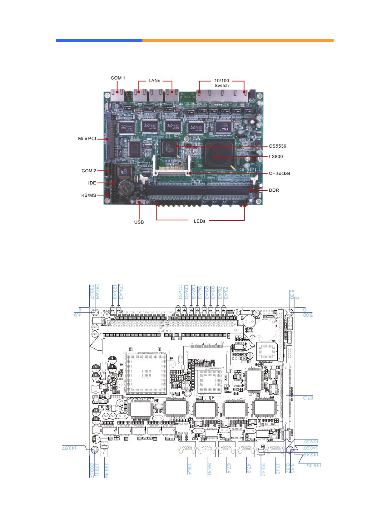
1.6 Board Layout
User’ s Manual
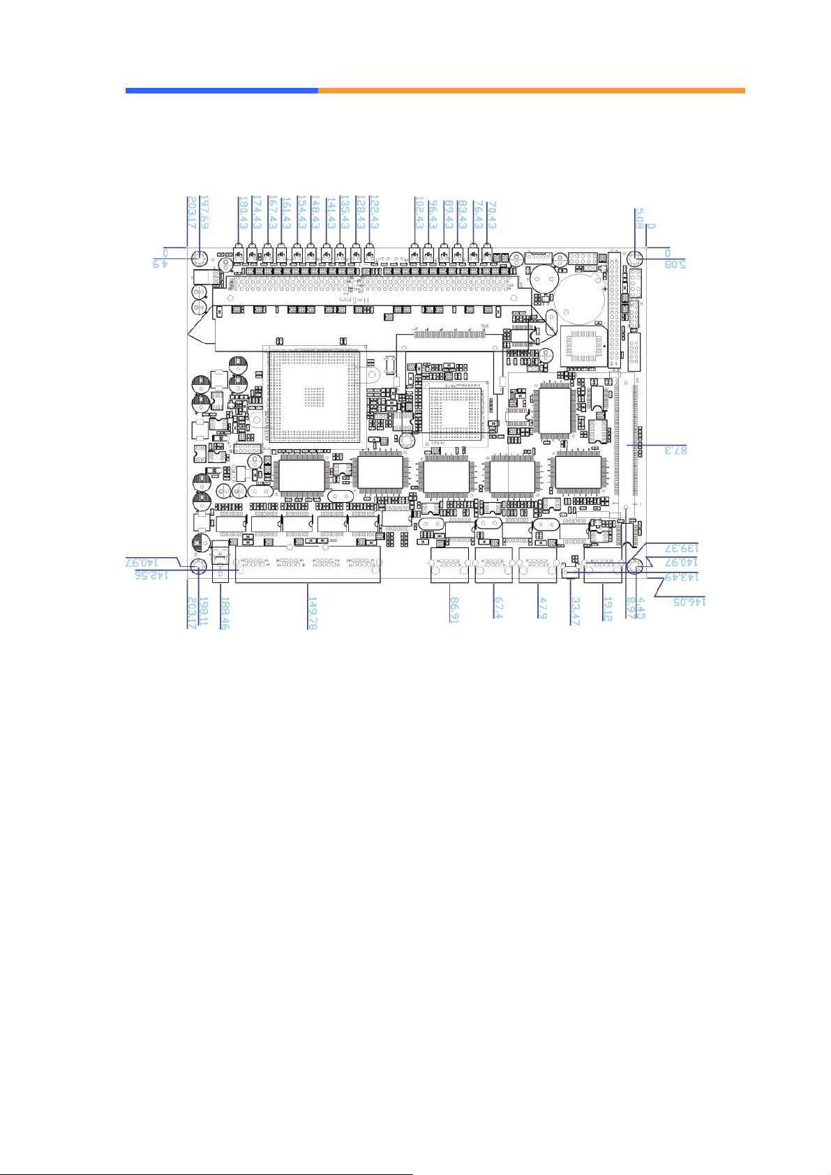
1.7 Board Dimension
CB-6971A-050
AEWIN Technologies Co., Ltd Aug, 2006
7
Page 8
User’ s Manual
CB-6971B-050
AEWIN Technologies Co., Ltd Aug, 2006
8
Page 9
User’ s Manual
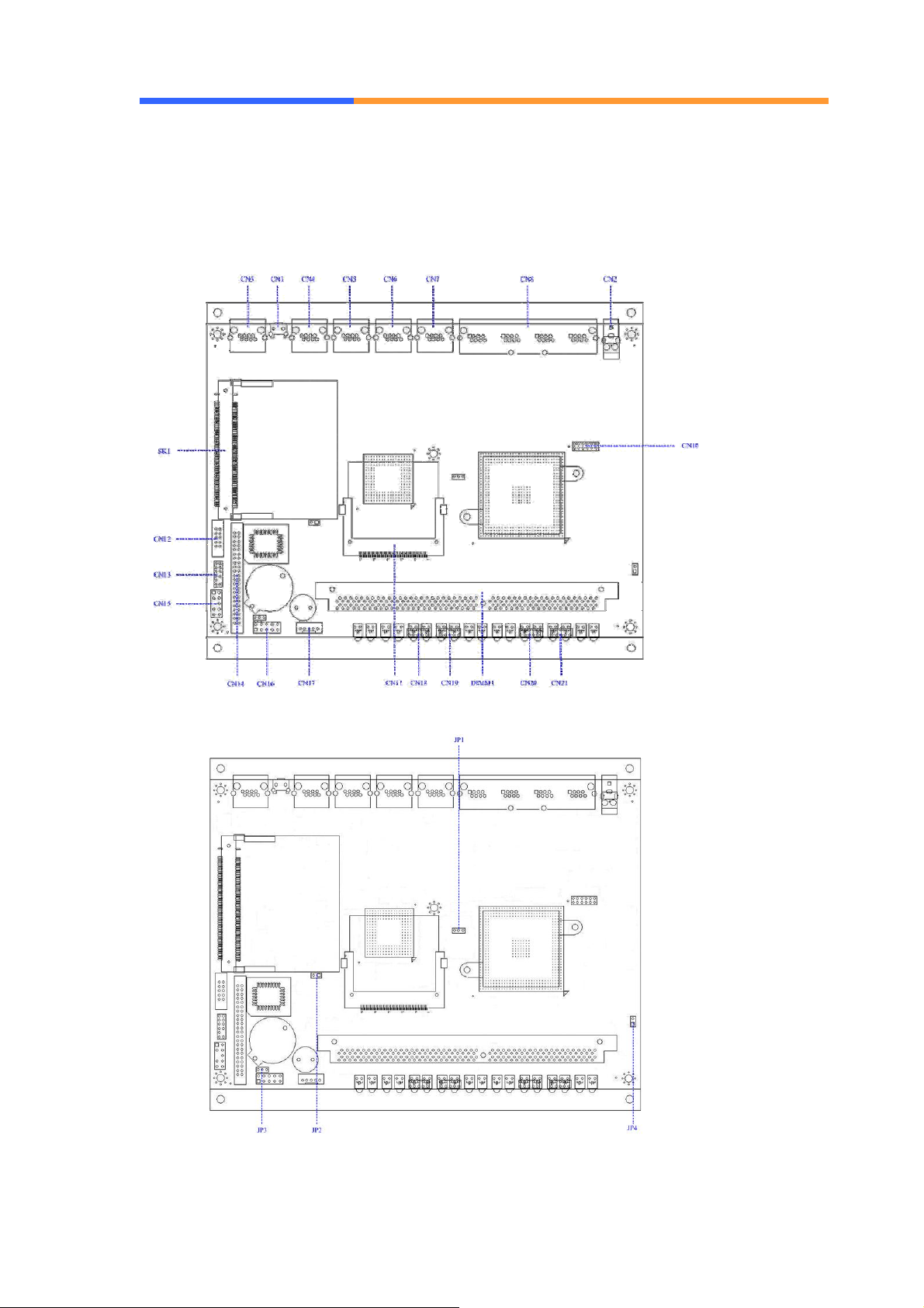
Chapter 2. Connector/Jumper Configuration
2.1 Connector/Jumper Location and Definition
AEWIN Technologies Co., Ltd Aug, 2006
9
Page 10
User’ s Manual
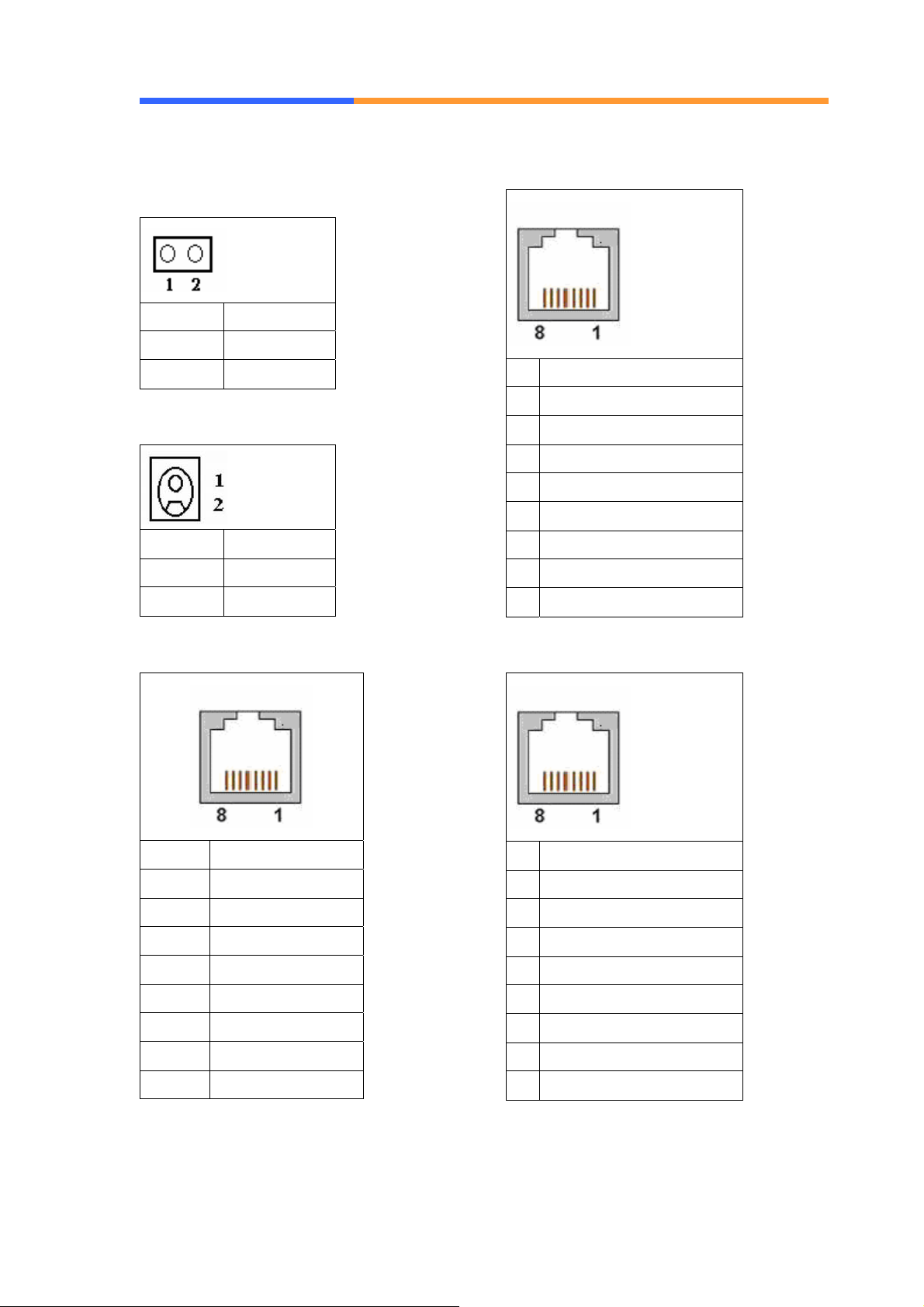
2.2 Connector and Jumper Setting
CN1: Reset button
Pin Define
1 Reset #
2 GND
CN2: External power jack
Pin Define
1 +5V
2 Ground
CN3: COM1 RJ45 connector
Pin Define
1 TX+
2 TX3 RX+
4 Chassis Ground
5 Chassis Ground
6 RX7 Chassis Ground
8 Chassis Ground
CN8: Four port switch
Pin Define
1 CTS#
2 DTR#
3 TXD#
4 Console Detect#
5 GND
6 RXD#
7 DSR#
8 RTX#
CN4/5/6/7: 10/100 RJ45 connector
AEWIN Technologies Co., Ltd Aug, 2006
10
Pin Define
1 TX+
2 TX3 RX+
4 Chassis Ground
5 Chassis Ground
6 RX7 Chassis Ground
8 Chassis Ground
CN10: VGA connector
Page 11
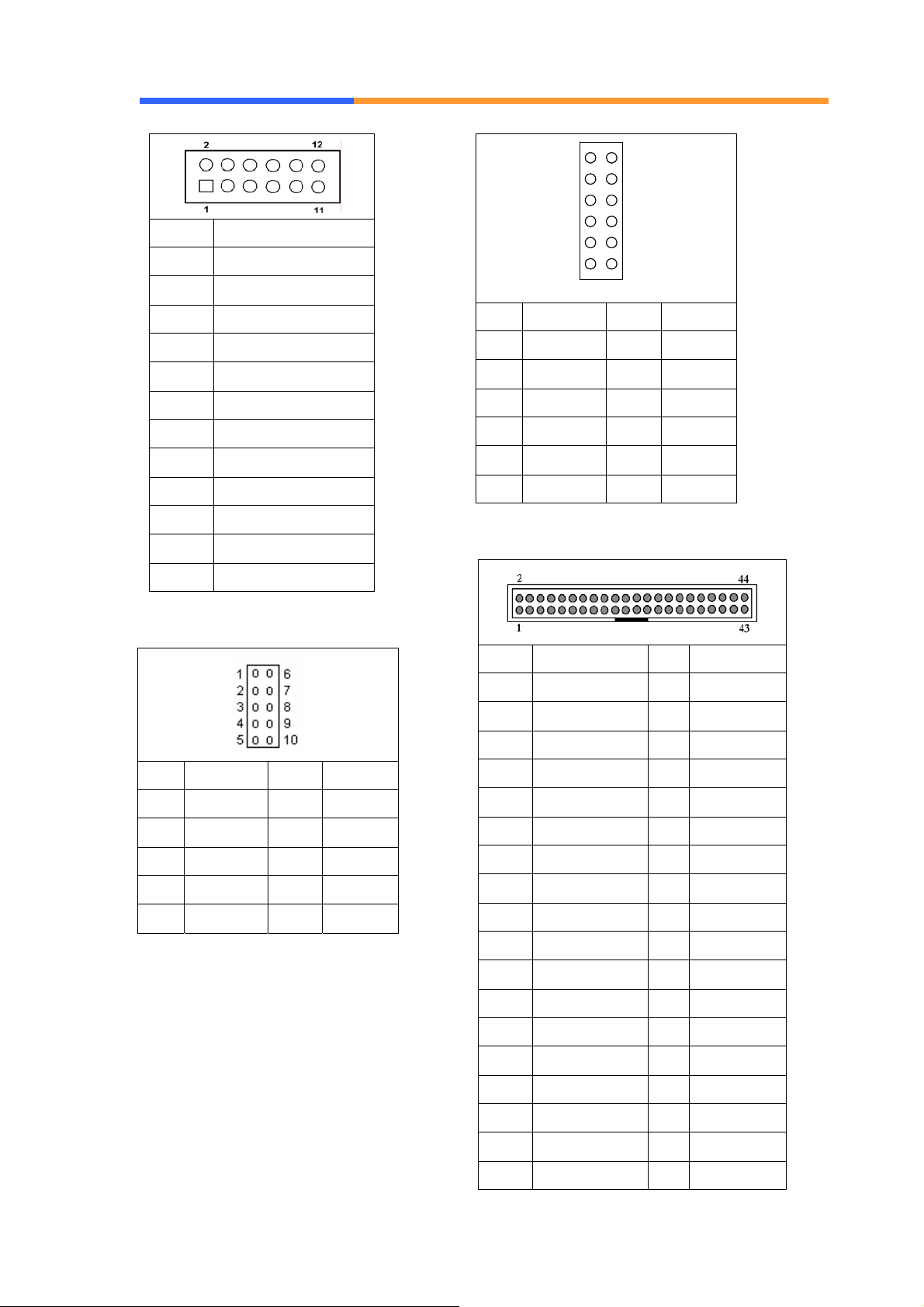
Pin Define
1 RED
User’ s Manual
11
11
1
1
3
3
5
5
7
7
9
9
2
2
4
4
6
6
8
8
10
10
12
12
2 GND
3 GREEN
4 +3.3V
5 BLUE
6 GND
7 GND
8 DDC DATA
9 DDC CLK
10 HSYNC
11 VSYNC
12 +5V
CN12: COM port pin header
Pin Define Pin Define
1 VCC3 2 LAD0
3 LAD1 4 LAD2
5 LAD3 6 LFRAME#
7 PCIRST# 8 VCC
9 CLK 10 KEY PIN
11 GND 12 GND
CN14: 44 Pin 2.0mm pitch IDE
Pin Define Pin Define
1 RSTPIDE# 2 Ground
3 PDD7 4 PDD8
Pin Define Pin Define
1 DCD# 6 DSR#
2 RXD# 7 RTS#
3 TXD# 8 CTS#
4 DTR# 9 RI#
5 Ground 10 NC
CN13: LPC bus connector
The connector is proprietary for LPC
port 80 card.
5 PDD6 6 PDD9
7 PDD5 8 PDD10
9 PDD4 10 PDD11
11 PDD3 12 PDD12
13 PDD2 14 PDD13
15 PDD1 16 PDD14
17 PDD0 18 PDD15
19 Ground 20 NC
21 PDDREQ 22 Ground
23 PDIOW# 24 Ground
25 PDIOR# 26 Ground
27 PDIORDY 28 Ground
29 PDDACK# 30 Ground
31 IRQ14 32 V5P0
33 PDA1 34 PD66#
35 PDA0 36 PDA2
AEWIN Technologies Co., Ltd Aug, 2006
11
Page 12
User’ s Manual
37 PDCS#1 38 PDCS#3
4 GND
39 PIDELED 40 Ground
41 V5P0 42 V5P0
43 Ground 44 N/C
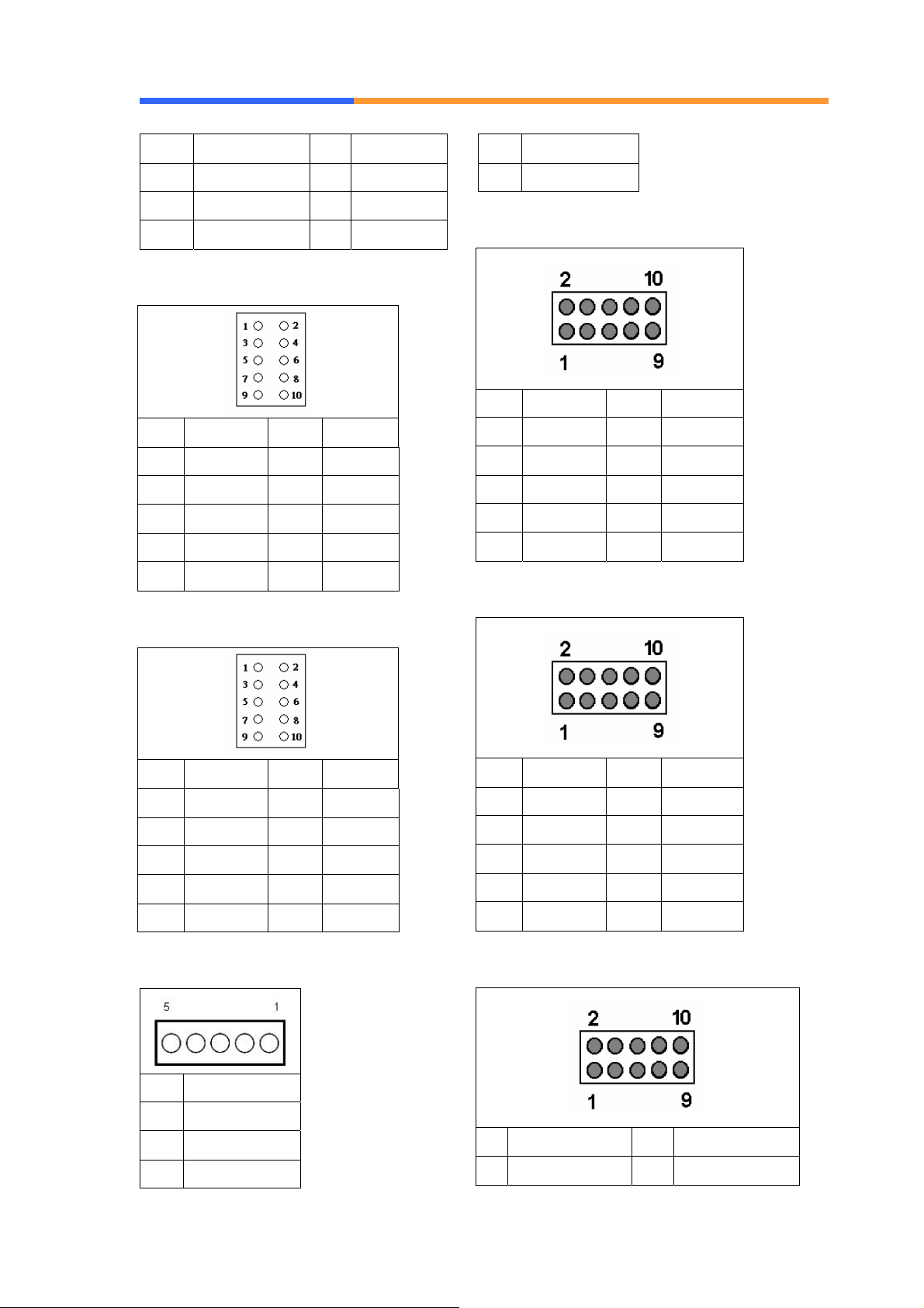
CN15: PS/2 Keyboard & Mouse
Pin Define Pin Define
1 KCLK 2 MCLK
3 KDAT 4 MDAT
5 Key Pin 6 NC
7 PS2_GND 8 PS2_GND
9 PS2_VCC 10 PS2_VCC
5 GND
CN18: LAN LED (Optional)
Pin Define Pin Define
1 LINK 1+ 2 LINK13 SPEED1+ 4 SPEED15 LINK2+ 6 LINK27 SPEED2+ 8 SPEED29 N/C 10 N/C
CN19: LAN LED (Optional)
CN16: GPIO
Pin Define Pin Define
1 +5V 2 GPIn0
3 GPin1 4 GPIn2
5 GPin3 6 GPout0
7 GPout1 8 GPout2
9 GPout3 10 GND
CN17: USB pin header
Pin Define Pin Define
1 LINK 3+ 2 LINK33 SPEED3+ 4 SPEED35 LINK4+ 6 LINK47 SPEED4+ 8 SPEED49 N/C 10 N/C
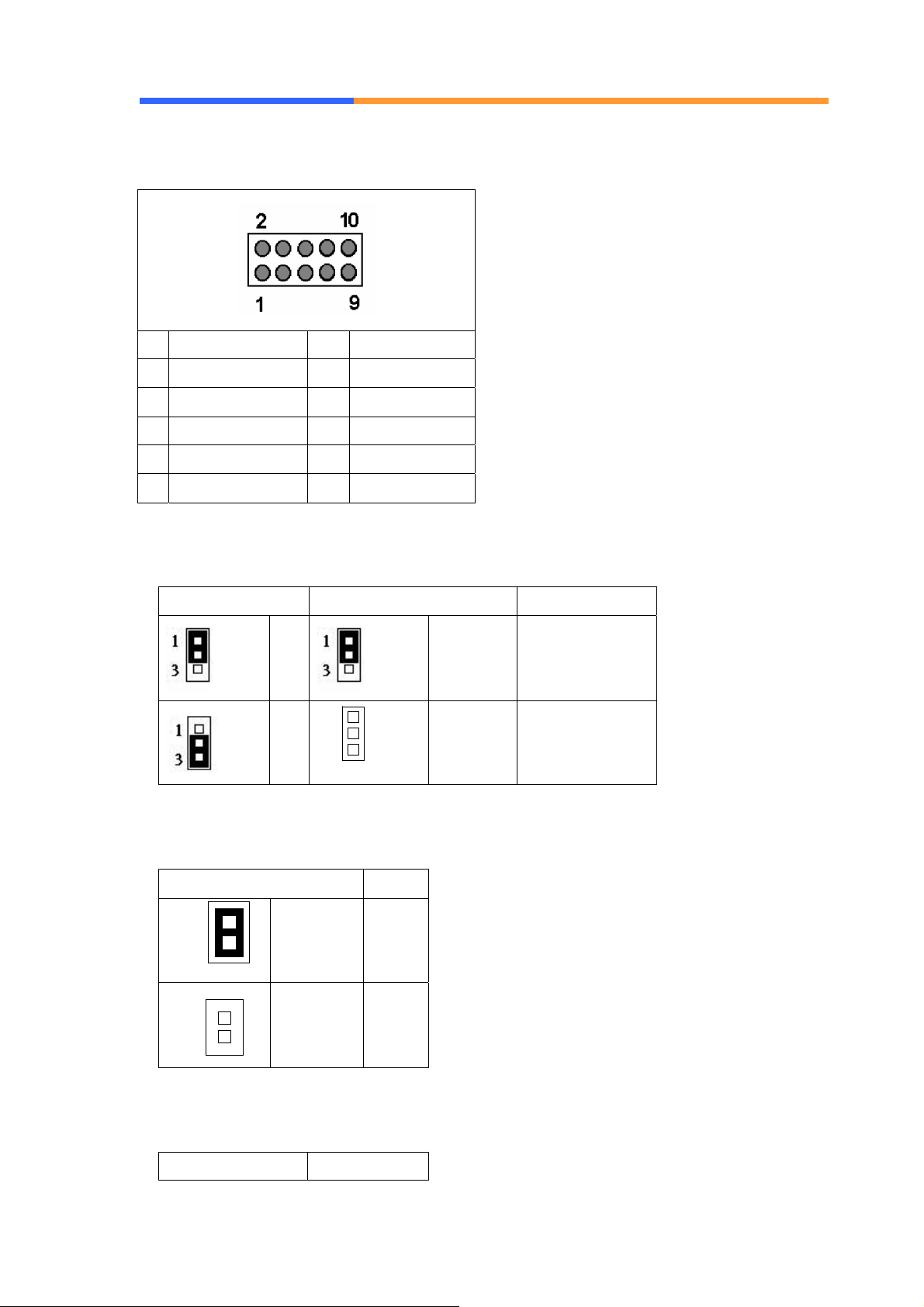
C20: Switch LED (Optional)
Pin Define
1 VSBVCC
2 DATA3 DATA+
AEWIN Technologies Co., Ltd Aug, 2006
Pin Define Pin Define
1 Switch 1 LINK+ 2 Switch 1 LINK-
12
Page 13

User’ s Manual
3 Switch 1
SPEED+
5 Switch 2 LINK+ 6 Switch 2 LINK-
4 Switch 1 SPEED-
7 Switch 2
SPEED+
9 Switch 3 LINK+ 10 Switch 3 LINK-
8 Switch 2 SPEED-
AEWIN Technologies Co., Ltd Aug, 2006
13
Page 14
User’ s Manual
C21: Switch/Power/HDD LED
Pin Define Pin Define
1 Switch 3 SPEED+ 2 Switch 3 SPEED3 Switch 4 LINK+ 4 Switch 4 LINK5 Switch 4 SPEED+ 6 Switch 4 SPEED7 IDE ACTIVE+ 8 IDE ACTIVE9 PW LED+ 10 PW LED-
JP1/JP4: DDR Speed & Voltage Detect
JP1 JP4 Setting
1-2
2-3
131
3
1-2 (ON) DDR-400/2.6V
1-2 (OFF) DDR-333/2.5V
JP2: Compact Flash Select
Pin Setting
121
2
1-2 (ON)
Master
(Default)
121
2
1-2 (OFF) Slave
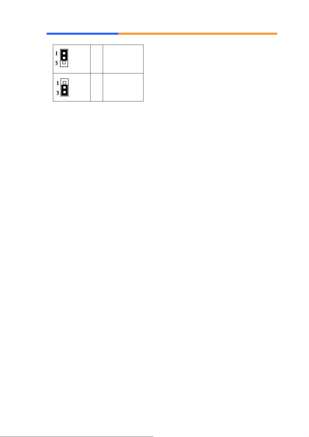
JP3: Clear CMOS
Pin Setting
AEWIN Technologies Co., Ltd Aug, 2006
14
Page 15
User’ s Manual
1-2
Normal
(Default)
2-3 Clear CMOS
AEWIN Technologies Co., Ltd Aug, 2006
15
Page 16

User’ s Manual
Chapter 3 BIOS Setup
The ROM chip of your CB-6971 board is configured with a customized Basic
Input/Output System (BIOS) from Phoenix-Award BIOS. The BIOS is a set of
permanently recorded program routines that give the system its fundamental
operational characteristics. It also tests the computer and determines how
the computer reacts to instructions that are part of programs.
The BIOS is made up of code and programs that provide the device-level
control for the major I/O devices in the system. It contains a set of routines
(called POST, for Power-On Self Test) that check out the system w hen you turn
it on. The BIOS also includes CMOS Setup program, so no disk-based setup
program is required CMOS RAM stores information for:
z Date and time
z Memory capacity of the main board
z Type of display adapter installed
z Number and type of disk drives
The CMOS memory is maintained by battery installed on the CB-6971 board.
By using the battery, all memory in CMOS can be retained when the system
power switch is turned off. The system BIOS also supports easy way to
reload the CMOS data when you replace the battery of the battery power lose.
3.1 Quick Setup
In most cases, you can quickly configure the system by choosing the following
main menu options:
1. Choose “Load Optimized Defaults” from the main menu. This loads the
setup default values from the BIOS Features Setup and Chipset Features
Setup screens.
2. Choose “Standard COS Features” from the main menu. This option lets
you configure the date and time, hard disk type, floppy disk drive type,
primary display and more.
3. In the main menu, press F10 (“Save & Exit Setup”) to save your changes
and reboot the system.
AEWIN Technologies Co., Ltd Aug, 2006
16
Page 17
User’ s Manual
3.2 Entering the CMOS Setup Program
Use the CMOS Setup program to modify the system parameters to reflect the
options installed in your system and to customize your system. For example,
you should run the Setup program after you:
z Received an error code at startup
z Install another disk drive
z Use your system after not having used it for a long time
z Find the original setup missing
z Replace the battery
z Change to a different type of CPU
z Run the Phoenix-Award Flash program to update the system BIOS
Run the CMOS Setup program after you turn on the system. On-screen
instructions explain how to use the program.
Enter the CMOS Setup program’s main menu as follows:
1. Turn on or reboot the system. After the BIOS performs a series of
diagnostic checks, the following message appears:
“Press DEL to enter SETUP”
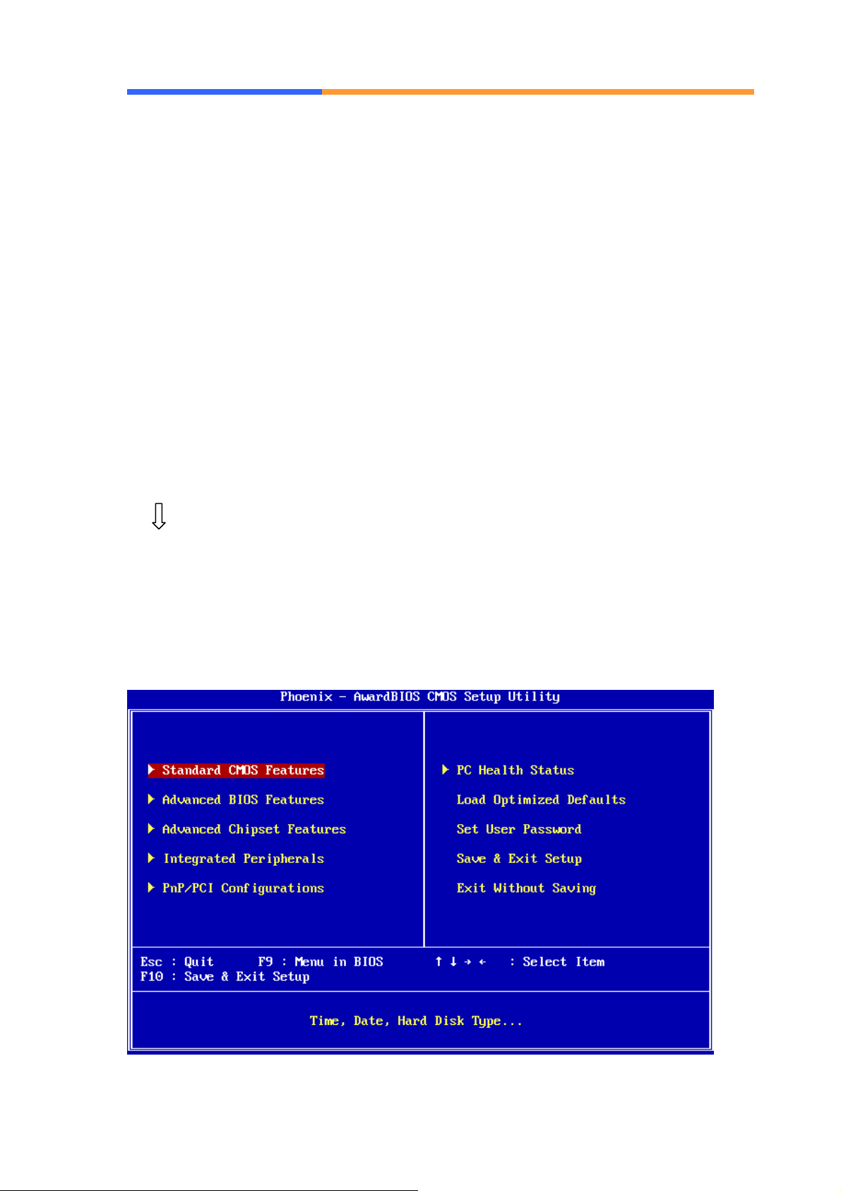
2. Press the <DEL> key to enter CMOS Setup program. The main
menu appears:
AEWIN Technologies Co., Ltd Aug, 2006
17
Page 18

User’ s Manual
3. Choose a setup option with the arrow keys and press <Enter>. See
the following sections for a brief description of each setup option.
In the main menu, press F10 (“Save & Exit Setup) to save your changes
and reboot the system. Choosing “EXIT WITHOUT SAVING” ignores
your changes and exits the program. Pressing <ESC> anywhere in the
program returns you to the main menu.
3.3 Menu Options
The main menu options of the CMOS Setup program are described in the
following and the following sections of this chapter.
STANDARD CMOS FEATURES:
Configure the date & time, hard disk drive type, floppy disk drive type, primary
display type and more
ADVANCED BIOS FEATURES:
Configure advanced system options such as enabling/disabling cache memory
and shadow RAM
ADVANCED CHIPSET FEATURES:
Configure advanced chipset register options such DRAM timing
INTEGRATED PERIPHERALS:
Configure onboard I/O functions
PNP/PCI CONFIGURATION:
Configure Plug & Play IRQ assignments and PCI slots
PC HEALTH STATUS:
Configure the CPU speed and, if the optional system monitor IC is installed,
view system information
LOAD OPTIMIZED DEFAULTS:
Loads optimized BIOS settings
SET USER PASSWORD:
Configure the system so that a password is required when the system boots or
AEWIN Technologies Co., Ltd Aug, 2006
18
Page 19
User’ s Manual
you attempt to enter the CMOS setup program. When you log in with this
password, you will be able to enter the CMOS Setup main menu, but you can
not enter other menus in the CMOS Setup program.
SAVE & EXIT SETUP:
Save changes of values to CMOS and exit the CMOS setup program
EXIT WITHOUT SAVING:
Abandon all CMOS changes and exit the CMOS setup program
3.4 Standard CMOS Features Setup
Use the Standard CMOS Setup option as follows:
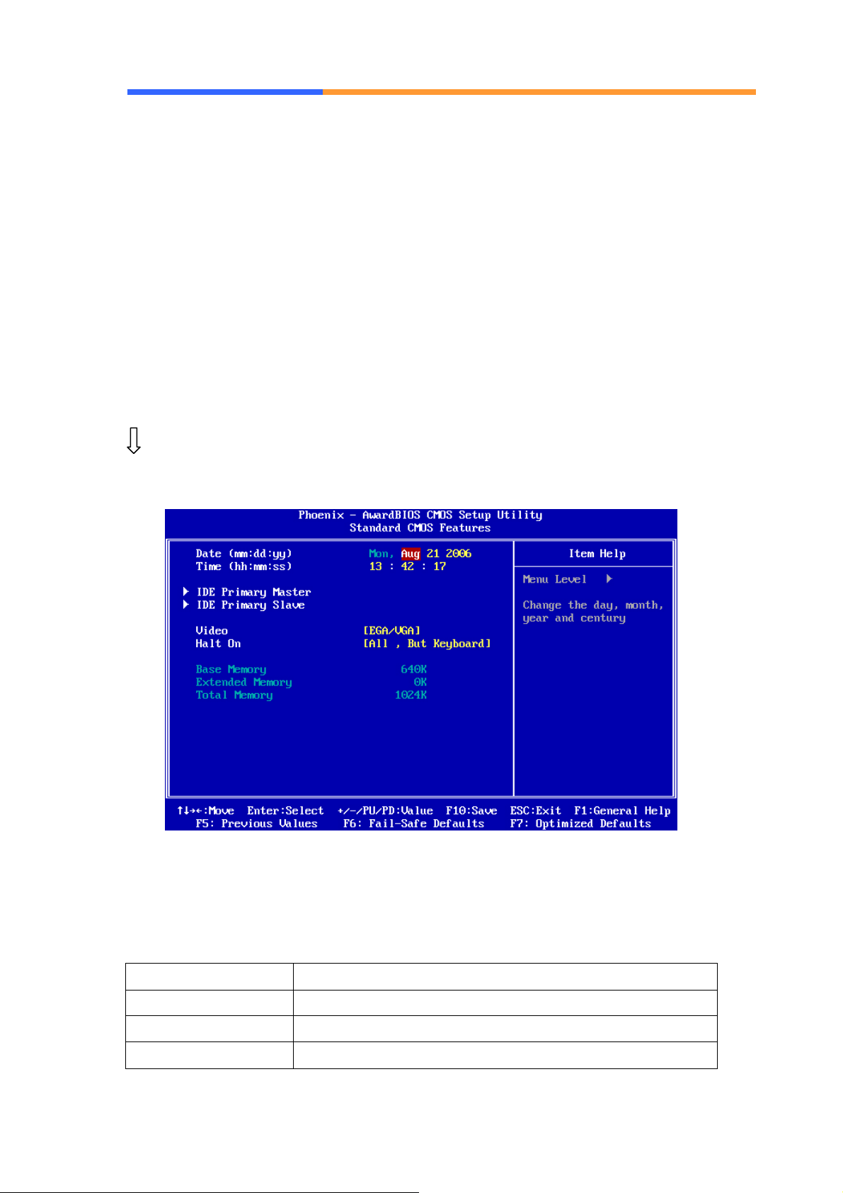
1. Choose “Standard CMOS Features” from the main menu. The following
screen appears:
2. Use the arrow keys to move between fields. Modify the selected field
using the PgUP/PgDN/+/- keys. Some fields let you enter numeric values
directly.
Option Description
Date (mm:dd:yy) Type the current date
Time (hour: min: sec) Type the current time (24-hour clock)
IDE channel Select from “Auto”, “User”, or “None”
AEWIN Technologies Co., Ltd Aug, 2006
19
Page 20
User’ s Manual
If your drive is not one of the predefined types, choose
“User” and enter the following drive specifications:
Cylinders, heads, Wpcom, L-Zone, sectors, and mode
Consult the documentation received with the drive for
the values that will give you optimum performance.
Video Select the default video device: EGA/VGA, CGA 40,
CGA 80, Mono
Halt On Select the situation what you want BIOS to stop power
on self test process and notice you.
Choose: <All Errors> <No Errors/ All> <But Keyboard>
<All, But Diskette> <All, But Disk/Key>
3. After you have finished with the Standard CMOS Features program, press
the <ESC> key to return to the main menu.
3.5 Advanced BIOS Features Setup
Use the Advanced BIOS Features Setup option as follows:
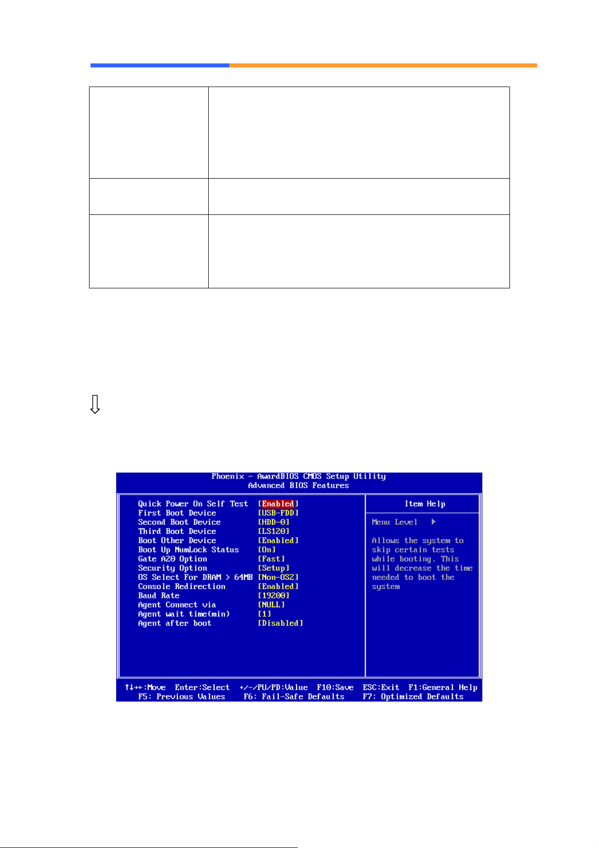
1. Choose “Advanced BIOS Features Setup” from the main menu. The
following screen appears:
2. Use the arrow keys to move between items and to select values. Modify
the selected fields using the PgUP/PgDN keys. Press the <F1> “Help”
AEWIN Technologies Co., Ltd Aug, 2006
20
Page 21

User’ s Manual
key for information on the available options:
Option Description
Quick Power On Self Test Skip some checking items and speed up the
power on process.
First/Second/Third Boot
Device
The BIOS attempts to load the operating
system from the devices in the sequence
selected in these items. Choose: HDD-0,
LS-120, USB FDD…..
Boot Other Device Set up other device to be bootable.
Boot Up NumLock Status Select power on status of NumLock.
Gate A20 Option Gate A20 is a device used to address memory
above 1 MB.
Fast (Default): Select chipset controller to
control Gate 20.
Normal: Select Keyboard controller to control
Gate 20.
Security Option Select whether the password is required for
system boot or enter Setup menu.
System: the system will not boot and not access
Setup menu if the password is wrong.
Setup: the system can boot, but not allow to
access Setup menu if the password is wrong.
OS Select for DRAM > 64MB Select OS/2 if your system is using OS/2 and
has a memory size of more than 64MB.
Default is Non-OS2.
Console Redirection Choose <enabled> allowing connecting the
server of hyper terminal to monitor client side.
It has to be worked under DOS mode, and the
client terminal doesn’t need graphic function.
Baud Rate The data transfer rate (bit per second) to agent.
Choose 9600/19200/38400/57600/1 15200 item.
Agent Connect via Select <Null> to let agent connect directly.
Agent wait time (min) Agent negotiate time, choose 1/2/4/8 min.
Agent after boot Choose <enabled> for agent to administrate the
system after boot.
AEWIN Technologies Co., Ltd Aug, 2006
21
Page 22
User’ s Manual
3.6 Advanced Chipset Features Setup
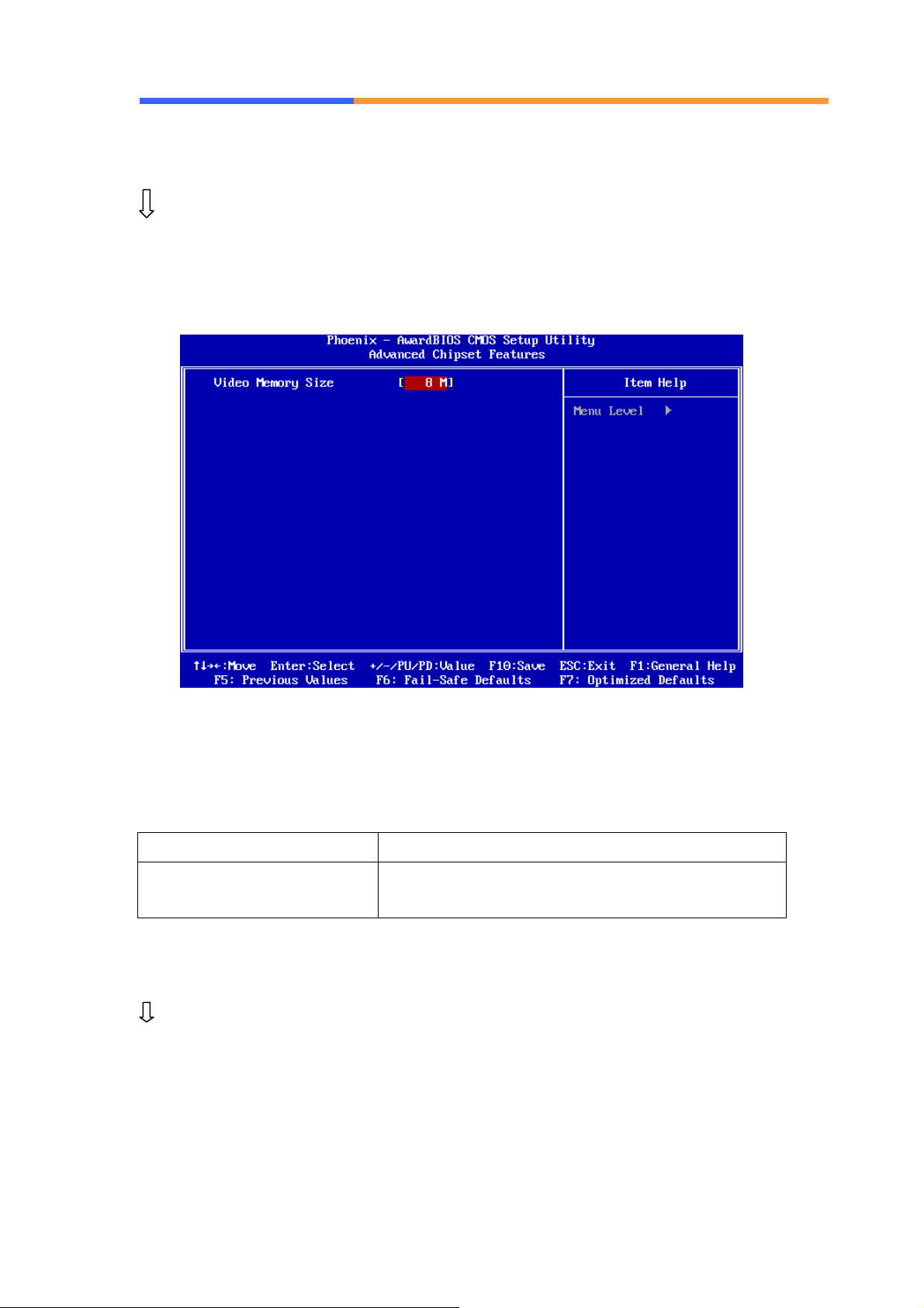
Use the Advanced Chipset Features Setup option as follows:
1. Choose “Advanced Chipset Features Setup” from the main menu. The
following screen appears;
2. Move between items and select values by using the arrow keys. Modify the
selected fields using the PnUP/PgDN Keys. For information on the various
options, press
<F1> key .
Option Description
Video Memory Size Select the amount of memory taken from system
memory to be used by onboard video hardware.
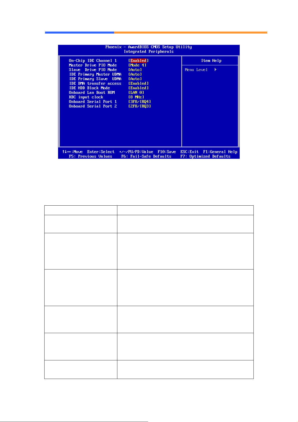
3.7 Integrated Peripherals
Use the Integrated Peripherals Setup option as follows:
1. Choose “Integrated Peripherals Setup” from the main menu. The
following screen appears:
AEWIN Technologies Co., Ltd Aug, 2006
22
Page 23
User’ s Manual
2. Move between items and select values by using the arrow keys. Modify
the selected fields using the PgUP/PgDN keys. Please press the <F1>
key for information on the various options.
Option Description
OnChip IDE Channel 1 Select Enabled to activate the primary IDE
interface.
Master Drive PIO Mode Allow you to set a PIO (Programmed Input/Output)
mode (0-4) for Master IDE drive that the onboard
IDE interface supports. In Auto mode, the system
automatically determines the best mode.
Slave Drive PIO Mode Allow you to set a PIO (Programmed Input/Output)
mode (0-4) for Slave IDE drive that the onboard
IDE interface supports. In Auto mode, the system
automatically determines the best mode.
IDE Primary Master UDMA If the device in IDE Primary Master interface and
operation system supports DMA, select Auto to
enable UltraDMA33/66/100 implementation.
IDE Primary Slave UDMA If the device in IDE Primary Slave interface and
operation system supports DMA, select Auto to
enable UltraDMA33/66/100 implementation.
IDE DMA transfer access Allow you to enable or disable DMA (Direct
Memory Access) support for all IDE devices.
AEWIN Technologies Co., Ltd Aug, 2006
23
Page 24
User’ s Manual
A
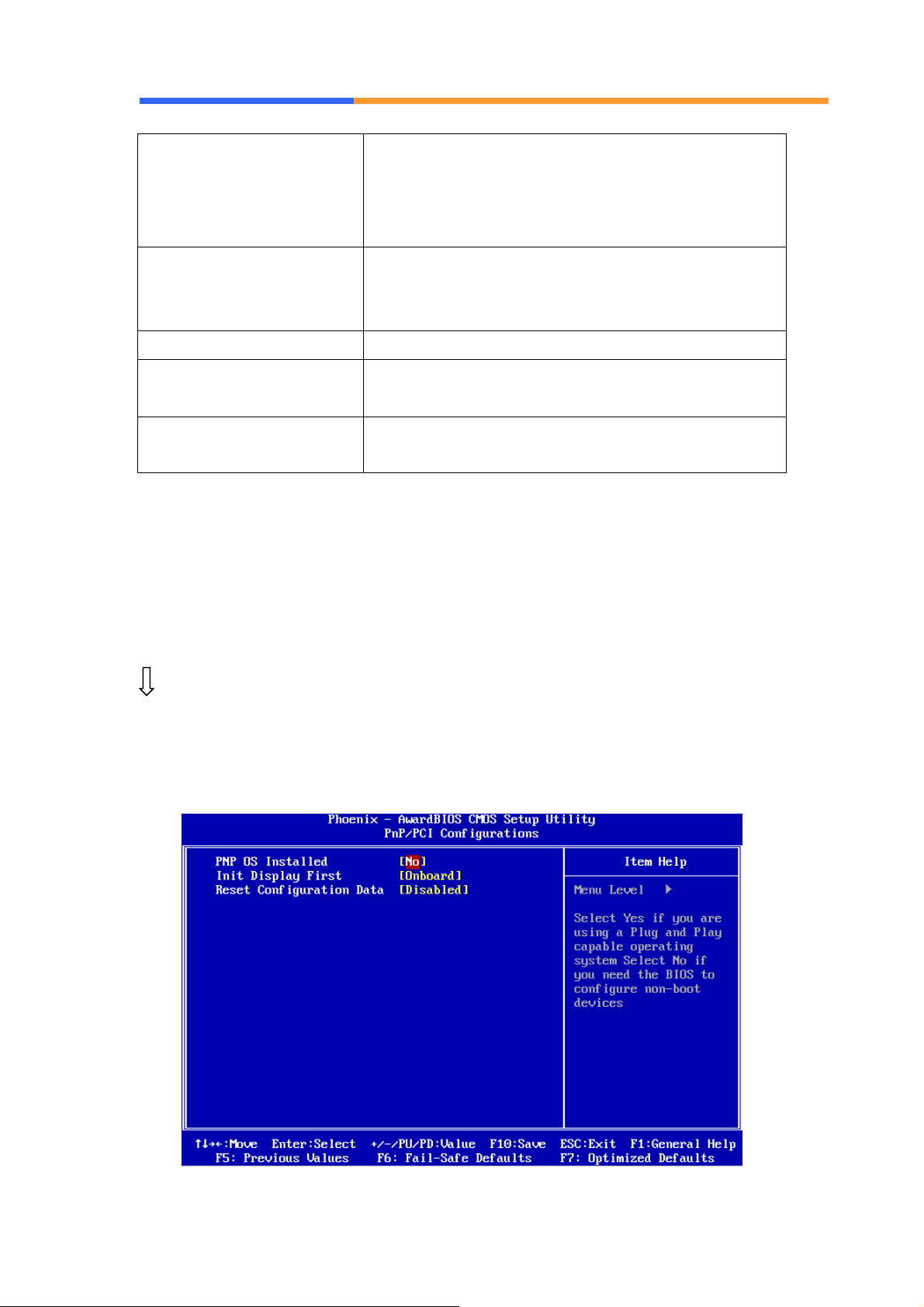
IDE HDD Block Mode Enabled to speed up hard disk access by
transferring data from multiple sectors at once
instead of using the old single sector transfer
mode.
Onboard Lan Boot ROM
KBC Input Clock Allow you to set keyboard controller frequency.
Onboard Serial Port 1 Set onboard serial port 1, the options are
Onboard Serial Port 2 Set onboard serial port 2, the options are
llow you to enable or disable the booting from the
onboard LAN or a network add-in card with a
remote boot ROM installed.
3F8/IRQ4、2F8/IRQ3、3E8/IRQ4、2E8/IRQ3、AUTO.
3F8/IRQ4、2F8/IRQ3、3E8/IRQ4、2E8/IRQ3、AUTO
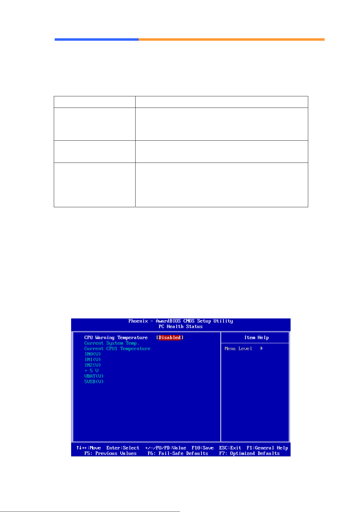
3.8 PNP/PCI Configuration
This option is used to configure Plug and Play assignments and route PCI
interrupts to designated ISA interrupts.
Use the PNP/PCI Configuration Setup option as follows:
1. Choose “PNP/PCI Configuration Setup” from the main menu, the following
screen appears.
AEWIN Technologies Co., Ltd Aug, 2006
24
Page 25
User’ s Manual
2. Move between items and select values by using the arrow keys. Modify
the selected fields using the PgUP/PgDN keys. For information on the
various options, please press <F1> key.
Option Description
PNP OS installed NO: BIOS program will adjust all the set up by itself
YES: When you install the system that support plug &
play, press <YES>
Init Display First Allow to choose the priority of PCI VGA card or
onboard.
Reset Configuration
Data
3. Please press the <ESC> key to return the main menu after finishing with
the PNP/PCI Configuration Setup.
Enabled will reset the Extended System
Configuration Data (ESCD) once automatically. It will
then recreate a new set of configure data.
Disabled will not reset the configuration data.
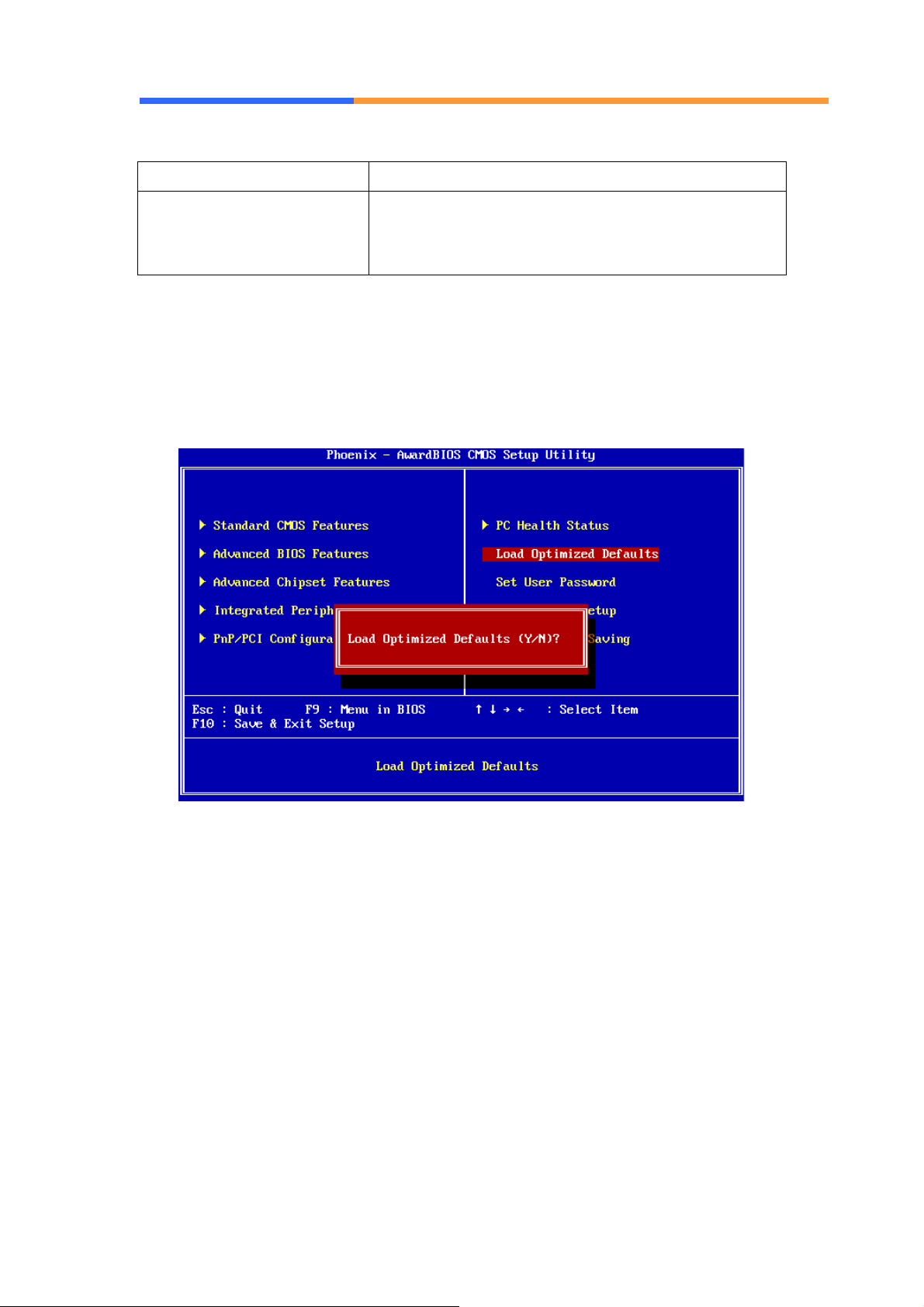
3.9 PC Health Status Configuration Setup
Choose “PC Health Status Configuration Setup” from the main menu, the
following screen appears:
AEWIN Technologies Co., Ltd Aug, 2006
25
Page 26
User’ s Manual
Option Description
CPU Warning Temperature An alarm will beep when the CPU temperature is
higher than the maximum limit. The default is
<Disabled> and alarm will not beep.
3.10 Load Optimized Defaults
This option loads optimized settings stored in the BIOS ROM. The
auto-configured settings do not affect the Standard CMOS Setup screen.
To use this feature, highlight it on the main screen and press <Enter>. A line
will appear on the screen asking if you want to load the Optimized Default
Values. Press the <Y> key and then press <Enter> if you want to load the
SETUP default.
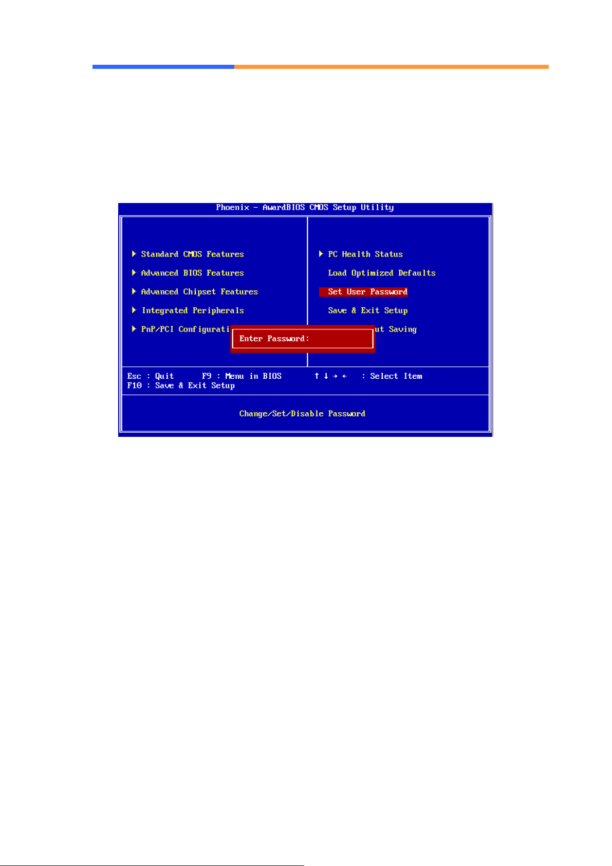
3.11 Set User Password
The password options let you prevent unauthorized system boot-up or
unauthorized use of CMOS setup. The User Password allows access to the
system and the CMOS Setup Utility main menu.
The password functions are disabled by default. You can use these options
to enable a password function or, if a password function is already enabled,
change the password.
AEWIN Technologies Co., Ltd Aug, 2006
26
Page 27
User’ s Manual
To change a password, first choose a password option from the main menu
and enter the current password. Then type your new password at the prompt.
The password is case sensitive and you can use up to 8 alphanumeric
characters. Press <Enter> after entering the password. At the Next Prompt,
confirm the new password by typing it and pressing <Enter> again.
After you use this option to enable a password function, use the “Security
Option” in “BIOS Feature Setup” to specify whether a password is required
every time the system boots or only when an attempt is made to enter the
CMOS Setup program.
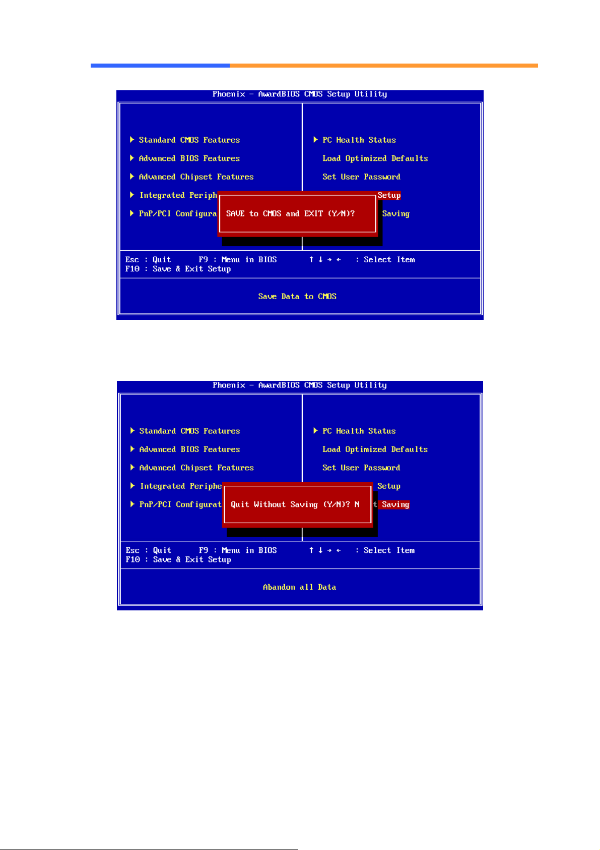
3.12 Save and Exit Setup
This function automatically saves all CMOS values before exiting Setup.
AEWIN Technologies Co., Ltd Aug, 2006
27
Page 28
User’ s Manual
3.13 Exit Without Saving
Use this function to exit Setup without saving the CMOS value.
AEWIN Technologies Co., Ltd Aug, 2006
28
Page 29
User’ s Manual
Chapter 4. Utility & Driver Installation
4.1 Operation System Supporting
CB-6971 can support Windows® and Linux® operation system as follows. Before
installation, please check your OS version. If your OS is not in the following list,
please upgrade your OS version.
OS Version
Windows® Windows® 2000 SP4/Windows® XP SP2
Linux® Fedora Core 2/Linux® 2.6 or above
4.2 System Driver Installation
CB-6971 offers the system driver in the setup CD. Please install the driver follow
the below procedures.
1. Click the [Device Manager] tab.
2. Choose "Entertainment Encryption/Decryption Device" in Other Devices.
3. Right click it and pick update driver.
4. Choose "Install from a list or specific location" and click next.
5. Choose "Don't search. I will choose the driver to install." and click next.
6. Choose "Show All Devices", select "Have Disk".
7. Aim at the Setup CD and click OK.
8. Find "Geode LX AES Crypto Driver", click next.
9. Following the instruction to finish the installation.
4.3 VGA Driver Installation
CB-6971 offers the VGA driver in the setup CD. Please install the driver follow the
below procedures.
1. Click the [Device Manager] tab.
2. Choose “Video Controller (VGA Compatible)” in Other Devices.
3. Right click it and pick update driver.
4. Choose "Install from a list or specific location" and click next.
5. Choose "Don't search. I will choose the driver to install." and click next.
6. Choose "Display Adapters".
7. Aim at the Setup CD and click OK.
AEWIN Technologies Co., Ltd Aug, 2006
29
Page 30
User’ s Manual
8. Find the suitable driver file, click next.
9. Following the instruction to finish the installation.
4.4 LAN Driver Installation
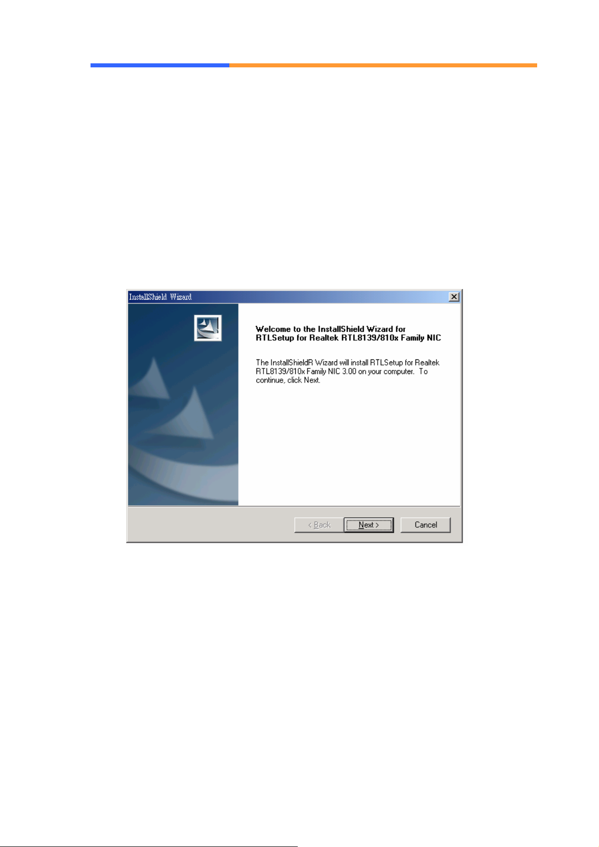
CB-6971 support Ethernet controlled by using Realtek® 8139CL+ chipset. Please
install the driver follow the below procedures.
1. Insert the setup CD of CB-6971 into your CD-ROM drive.
2. Choose the Drivers file to click the Setup icon.
3. Click [Next] button.
AEWIN Technologies Co., Ltd Aug, 2006
30
Page 31
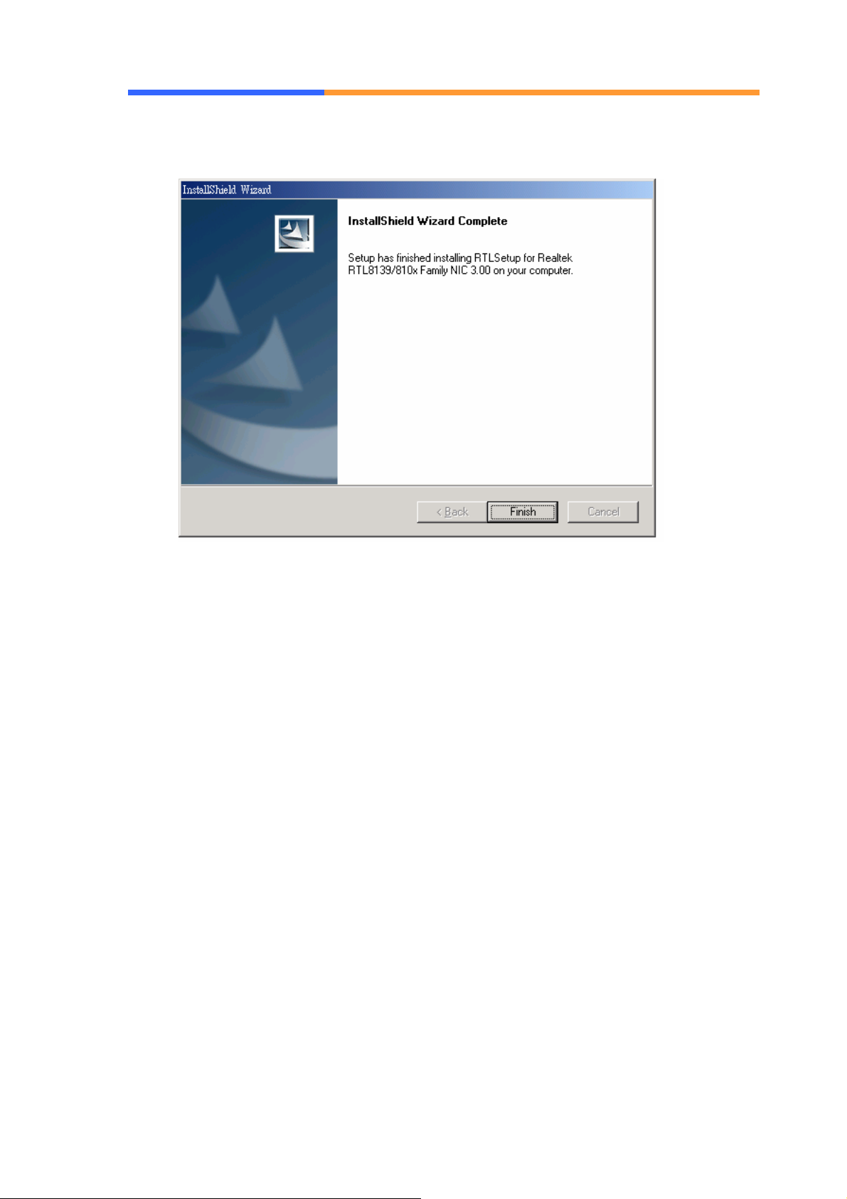
4. Click [Finish] button.
User’ s Manual
AEWIN Technologies Co., Ltd Aug, 2006
31
Page 32

User’ s Manual
Appendix A: Optional Accessory and Cable List
The VGA header of CB-6971 must work via additional adapter card and cable
as follows. It can be for customer to test or developing use.
Part No. Item Description
MB06018-1-01
46-I0002X6-00
VGA adapter card Adapter Module of VGA header
2*6 Cable 2mm, 20cm cable of MB06018
AEWIN Technologies Co., Ltd Aug, 2006
32
 Loading...