

Page 1

User’ s Manual
Networking Control Board
Model Number CB-6970
VIA® C7TM/EdenTM Networking Control Board with Four 100/10 LAN
User’ s Manual
Version 1.1
©2006 AEWIN Technologies Co., Ltd. All rights reserved. Ver 1.1. Aug, 2006
1
Page 2

User’ s Manual
© Copyright 2006. All Rights Reserved
Quick Installation Guide Edition 1.1, Aug 2006
This document contains proprietary information protected by copyright. All rights are reserved; no part of this manual may be
reproduced, copied, translated or transmitted in any form or by any means without prior written permission of the
manufacturer.
The content of this document is intended to be accurate and reliable; the original manufacturer assumes no responsibility for
any inaccuracies that may be contained in this manual. The original manufacturer reserves the right to make improvements
to the products described in this manual at any time without prior notice.
Trademarks
IBM, EGA, VGA, XT/AT, OS/2 and PS/2 are registered trademarks of International business Machine Corporation
Award is a trademark of Award Software International, Inc
Intel is a trademark of Intel
RTL is a trademark of Realtek
VIA is a trademark of VIA Technologies, Inc
Microsoft, Windows, Windows NT and MS-DOS are either trademarks or registered trademarks of Microsoft Corporation
All other product names mentioned herein are used for identification purpose only and may be trademarks and/or registered
trademarks of their respective companies
Limitation of Liability
While reasonable efforts have been made to ensure the accuracy of this document, the manufacturer and distributor assume
no liability resulting from errors or omissions in this document, or from the use of the information contained herein.
For more information on CB-6970 or other AEWIN products, please visit our website
http://www.aewin.com.tw.
For technical supports or free catalog, please send your inquiry to
©2006 AEWIN Technologies Co., Ltd. All rights reserved. Ver 1.1. Aug, 2006
2
Page 3

User’ s Manual
Table of Contents
Chapter 1. General Information................................................................................ 5
1.1 Introduction................................................................................................... 5
1.2 Specification................................................................................................. 5
1.3 Order Information ......................................................................................... 5
1.4 Package........................................................................................................ 6
1.5 Precautions................................................................................................... 6
1.6 Board Layout................................................................................................ 8
1.7 Board Dimension.......................................................................................... 8
Chapter 2. Connector/Jumper Configuration ........................................................... 9
2.1 Connector/Jumper Location and Definition................................................... 9
2.2 Onboard Processor .................................................................................... 10
2.3 Connector and Jumper Setting...................................................................10
2.4 CompactFlashTM Socket Pin Assignment.................................................... 15
Chapter 3. BIOS Setup.......................................................................................... 16
3.1 Quick Setup................................................................................................16
3.2 Entering the CMOS Setup Program ........................................................... 17
3.3 Menu Options............................................................................................. 18
3.4 Standar d CMOS Features Setup................................................................ 19
3.5 Advanced BIOS Features Setup................................................................. 20
3.6 Advanced Chipset Features Setup ............................................................. 22
3.7 Integrated Peripherals ................................................................................ 24
3.8 Power Management Setup......................................................................... 25
3.9 PNP/PCI Configuration...............................................................................26
3.10 PC Health Status Configuration Setup...................................................... 28
3.11 Frequency/Voltage Control ....................................................................... 28
3.12 Load Fail-Safe Defaults............................................................................ 29
3.13 Load Optimized Defaults .......................................................................... 30
3.14 Supervisor/User Password....................................................................... 31
3.15 Save and Exit Setup................................................................................. 32
3.16 Exit Without Saving .................................................................................. 33
Chapter 4. Utility & Driver Installation .................................................................... 34
4.1 Operation System Supporting..................................................................... 34
4.2 System Driver Installation...........................................................................34
4.3 LAN Driver Installation................................................................................38
4.4 RAID Driver Installation .............................................................................. 42
4.5 VGA Driver Installation................................................................................ 46
Appendix A: Programming the Watchdog Timer .................................................... 47
©2006 AEWIN Technologies Co., Ltd. All rights reserved. Ver 1.1. Aug, 2006
3
Page 4

User’ s Manual
Appendix B: Optional LAN Module......................................................................... 49
Appendix C: Optional Cable List............................................................................ 49
©2006 AEWIN Technologies Co., Ltd. All rights reserved. Ver 1.1. Aug, 2006
4
Page 5

User’ s Manual
Chapter 1. General Information
1.1 Introduction
The CB-6970 is a networking control board based on VIA architecture with
CN700+VT8237R+ chipset supporting the C7TM/EdenTM CPU with 400MHz FSB.
The CB-6970 is equipped with four 10/100Mbps LAN ports, with two LAN ports
bypass function. It is designed for SMB/SOHO segment, suitable for Firewall, VPN,
Load Balancing, IPS, IDS, etc.
1.2 Specification
z CPU: VIA C7TM/EdenTM low power processor
z BIOS: Award® 4Mb Flash BIOS
z Chipset: VIA CN700 + VT8237R+
z I/O Chipset: Winbond® 83627HG
z Memory: One 240pin DDR II DIMM socket can support up to 1GB
z Enhanced IDE: One 40-pin IDE connector
z Serial port: Two RS-232 serial ports
z KB/Mouse: Supports PS/2 keyboard and mouse
z USB: Support two USB2.0/1.1 ports
z Mini PCI Expansion: One Mini PCI socket
z Display: Support CRT
z Ethernet: Four Intel® 82551ER or Realtek® 8139CL+ 10/100Mbps
z Bypass: Support two Ethernet LAN ports bypass function
z Digital I/O: Four digital input and four digital output
z SSD interface: One 50-pin CompactFlashTM TYPE II socket
z Watchdog timer: Can generate a system reset, support software selectable
timeout interval
z System Monitoring: Built in W83627HG; support temperatures, fan speed, voltage
monitoring function
z Power supply voltage: Single +12V (11.4V to 12.6V) power supply
z Max. Power Requirements: 80W
z Operating temperature: 32 to 140 ℉ (0 to 60℃)
z Board size: 8”(L) x 5.75”(W) (203mm x 146mm)
1.3 Order Information
We offer various combination of CB-6970 control board according to CPU speed,
©2006 AEWIN Technologies Co., Ltd. All rights reserved. Ver 1.1. Aug, 2006
5
Page 6

User’ s Manual
LAN chip, bypass function. They can match various needs from the market.
Model Description
VIA C7
TM
1.5GHz Processor/Four Intel® 82551ER LAN/Bypass function on
CB-6970A-150
CB-6970B-100
CB-6970C-040
two LAN ports
Limitation: Without PXE function, with RAID function
VIA C7
Limitation: Without PXE function, with RAID function
VIA Eden
bypass function
Limitation: with PXE function, without RAID function (only SATA IDE)
TM
1.0GHz Processor/Four Intel® 82551ER LAN, w/o bypass function
TM
(V4) 400MHz Processor/Four Realtek® 8139CL+ LAN, w/o
1.4 Package
Please make sure that the following items have been included in the package before
installation.
1. CB-6970 Control Board
2. Quick Installation Guide (Optional)
3. Cables (Optional)
4. CD-ROM that contains the following folders:
(1) Manual
(2) System Driver
(3) Ethernet Driver
(4) Utility Tools
If any item of above is missing or damaged, please contact your dealer or retailer
from whom you purchased the CB-6970. Keep the box and carton when you
probably ship or store CB-6970 in near future. After you unpack the goods, inspect
and make sure the packaging is intact. Do not plug the power adapter to the main
board of CB-6970 if you already find it appears damaged.
Note: Keep the CB-6970 in the original packaging until you start installation.
1.5 Precautions
Please make sure you properly ground yourself before handling the CB-6970 control
board or other system components. Electrostatic discharge can be easily damage
the CB-6970 control board.
Do not remove the anti-static packing until you are ready to install the CB-6970
©2006 AEWIN Technologies Co., Ltd. All rights reserved. Ver 1.1. Aug, 2006
6
Page 7

User’ s Manual
control board.
Ground yourself before removing any system component from it protective
anti-static packaging. To ground yourself, grasp the expansion slot covers or other
unpainted parts of the computer chassis.
Handle the CB-6970 control board by its edges and avoid touching the components
on it.
©2006 AEWIN Technologies Co., Ltd. All rights reserved. Ver 1.1. Aug, 2006
7
Page 8
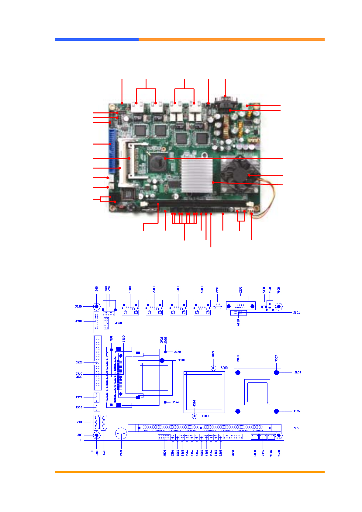
1.6 Board Layout
SATA Connectors
USB
KB/MS
VGA
EIDE Connector
CF Card Socket
Mini PCI Socket
HDD Power
System Fan
User’ s Manual
LAN *2 COM1USB
LAN * 2
with bypass
Reset
+12V DC IN
COM2
VT8237R+
C7/Eden CPU
CN700
1.7 Board Dimension
DDR2 Socket
GPIO LAN LED
LAN LED * 8
HDD
LED
Bypass
LED
Power
LED
Power
System
Fan
CPU Fan
©2006 AEWIN Technologies Co., Ltd. All rights reserved. Ver 1.1. Aug, 2006
8
Page 9
User’s Manual
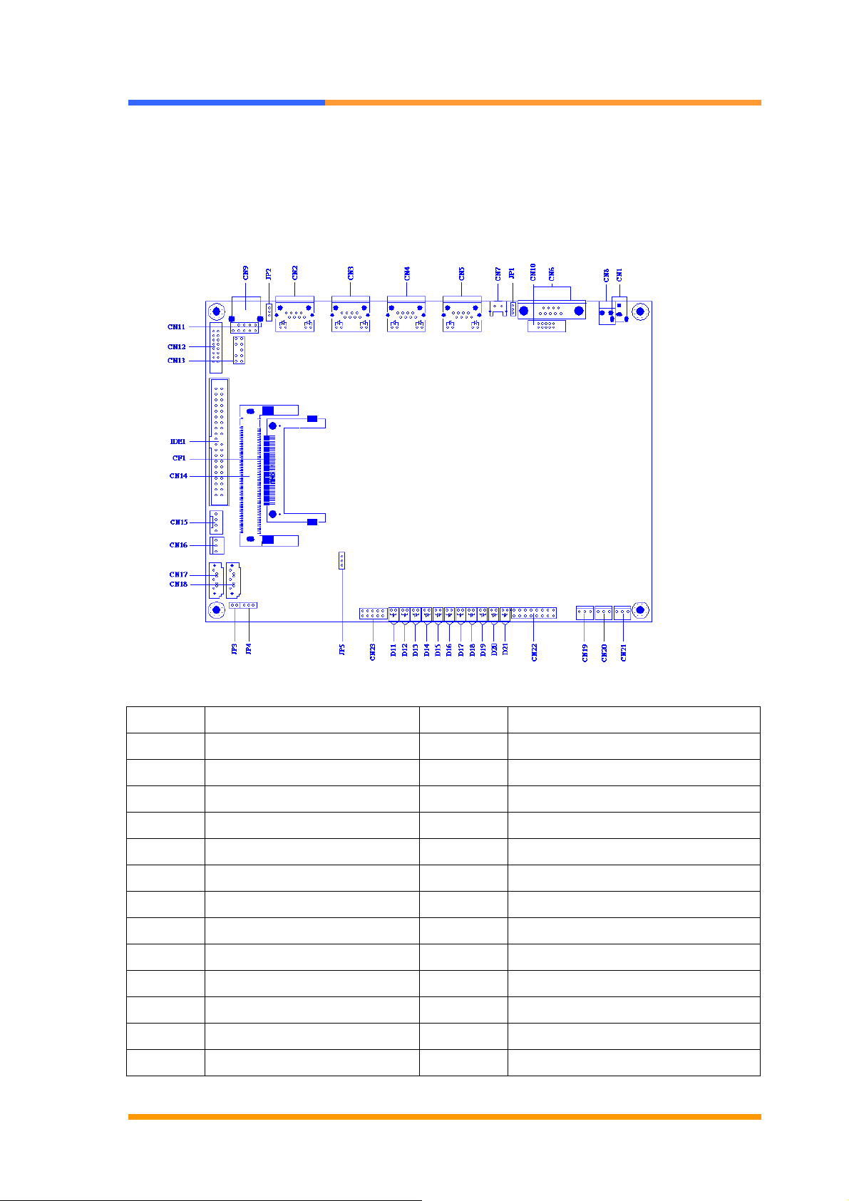
Chapter 2. Connector/Jumper Configuration
2.1 Connector/Jumper Location and Definition
Connector Description Connector Description
CN1 External Power Jack CN14 MINIPCI
CN2 LAN1 RJ-45 Connector CN15 IDE Power Connector
CN3 LAN2 RJ-45 Connector CN16 Fan Connector
CN4 LAN3 RJ-45 Connector CN17 SATA Connector
CN5 LAN4 RJ-45 Connector CN18 SATA Connector
CN6 COM Port (D-Sub) CN19/20/21 Fan Connector
CN7 Reset Button CN22 LAN LED Header
CN8 Internal Power Jack CN23 Manufacturer Default Using
CN9 USB Connector JP1 BY PASS / WATCH DOG SELECT
CN10 COM Port Pin Header JP2 BY PASS Mode Select
CN11 USB Pin Header JP3 CF Master/Slave Select
CN12 VGA Pin-header (2mm) JP4 Clear CMOS
CN13 KB/MS Pin-header JP5 CPU FSB Select
©2006 AEWIN Technologies Co., Ltd. All rights reserved. Ver 1.1. Aug, 2006
9
Page 10
User’s Manual
2.2 Onboard Processor
The CB-6970 can be VIA C7/ Eden nanobga2 packaging processors onboard. The
CPU is with 400MHz FSB and provides better performance. We offer two options
of VIA C7 1.5GHz or Eden 400MHz CPU.
2.3 Connector and Jumper Setting
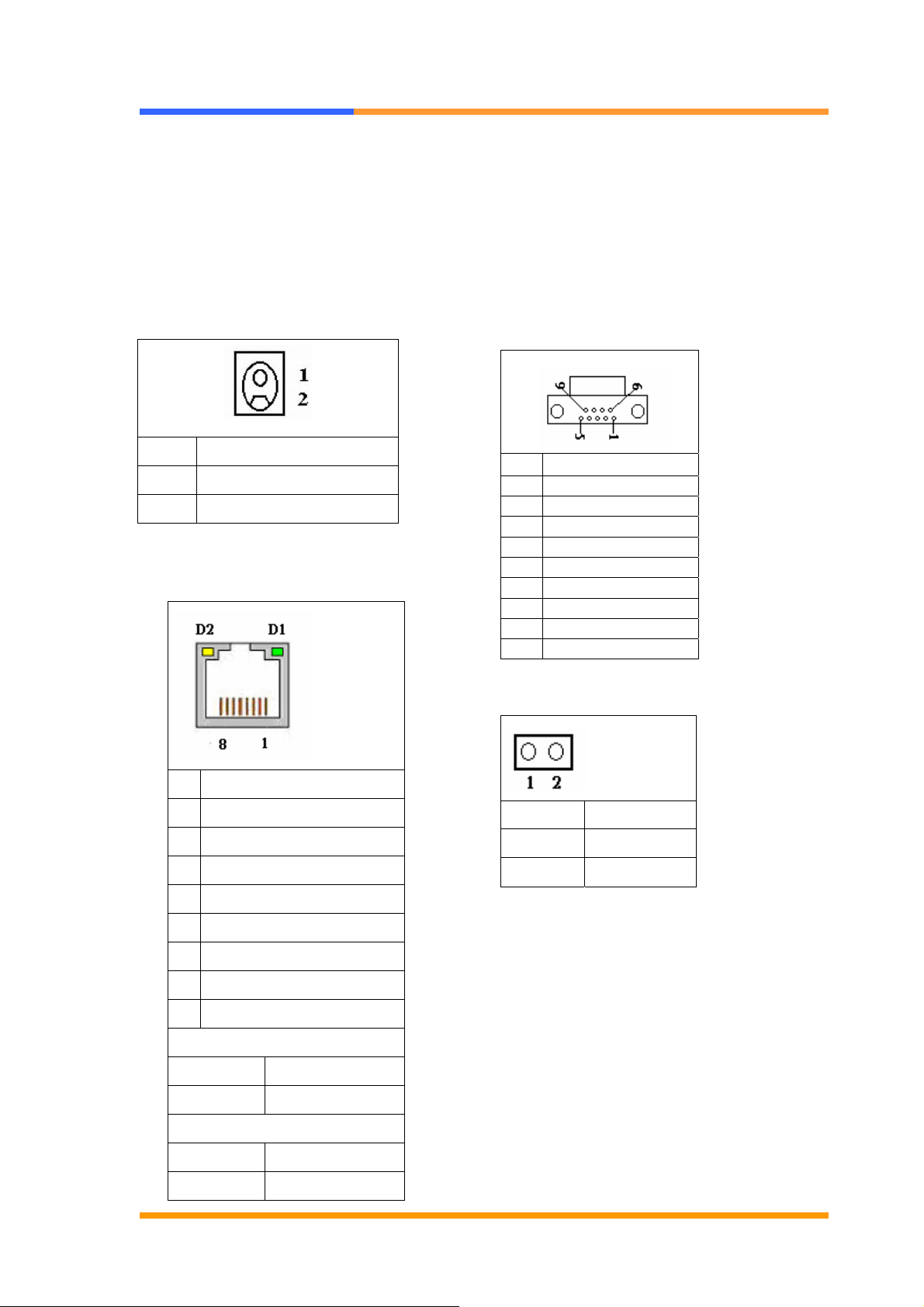
CN1: External Power Jack
Pin Define
1 +12V
2 Ground
CN2~CN5: LAN RJ-45 Connector
CN6: COM Port (D-Sub)
Pin Signal
1 DCD
2 RXD
3 TXD
4 DTR
5 Ground
6 DSR
7 RTS
8 CTS
9 RI
CN7: Reset Button
Pin Define
1 TX+
2 TX3 RX+
4 Chassis Ground
5 Chassis Ground
6 RX7 Chassis Ground
8 Chassis Ground
D1 :Link/Activity LED
Link YELLOW
Activity BLINKING
D2: Speed indicated LED
10 Mbps DIM
100 Mbps GREEN
©2006 AEWIN Technologies Co., Ltd. All rights reserved. Ver 1.1. Aug, 2006
10
Pin Define
1 Reset #
2 GND
Page 11
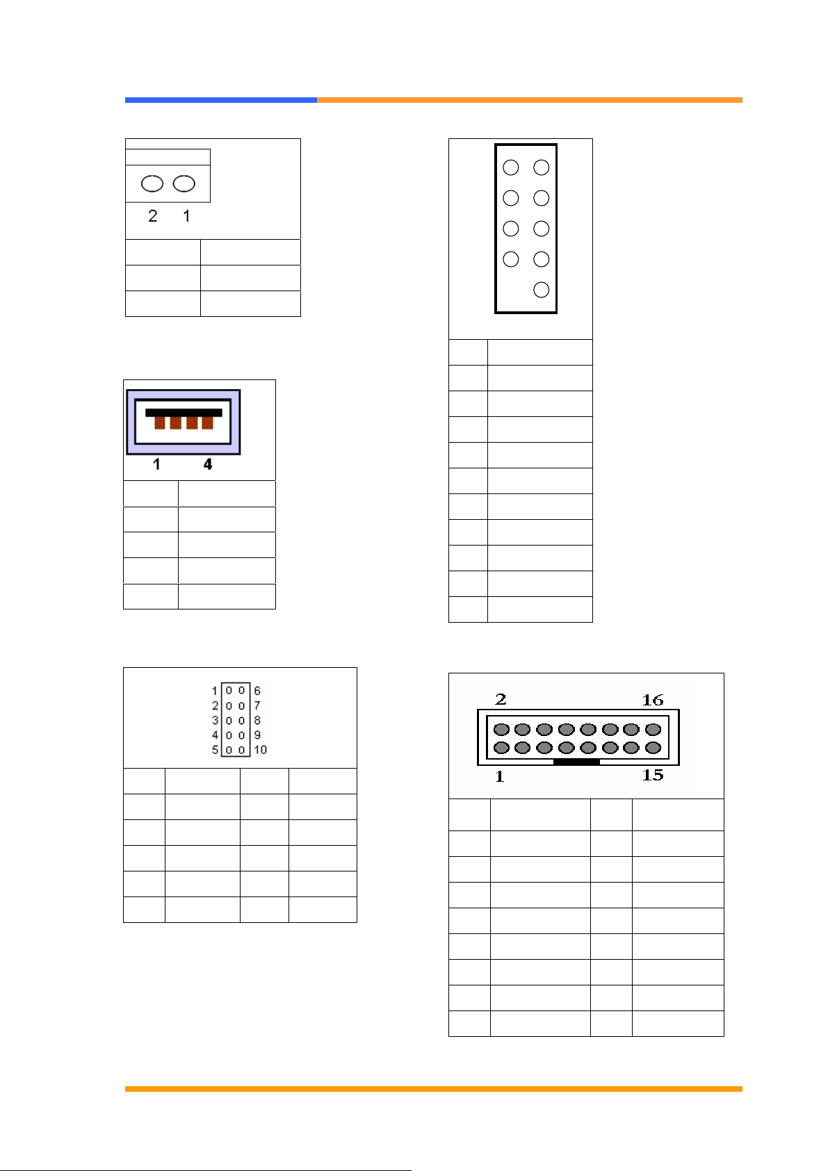
CN8: Internal Power Jack
User’s Manual
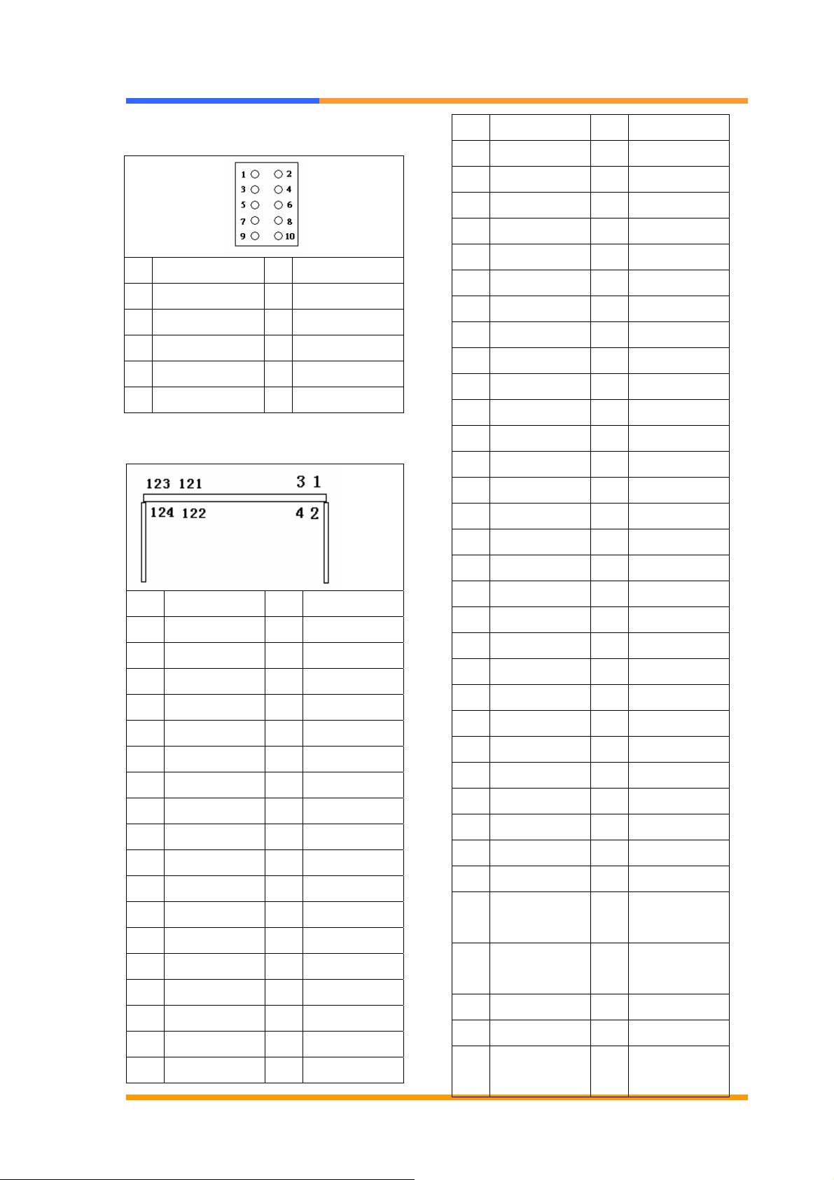
CN11: USB Pin Header
1 2
Pin Define
1 +12V
2 Ground
CN9: USB Connector
Pin Define
1 +5V
2 Data03 Data1+
4 Ground
CN10: COM Port Pin Header
10
Pin Define
1 USBVCC(+5V)
2 USBVCC(+5V)
3 USB24 USB35 USB2+
6 USB3+
7 GND
8 GND
9 KEY-Pin
10 GND
CN12: VGA Pin Header
Pin Define Pin Define
1 DCD# 6 DSR#
2 RXD# 7 RTS#
3 TXD# 8 CTS#
4 DTR# 9 RI#2
5 Ground 10 NC
Pin Define Pin Define
1 RED 2 Green
3 Blue 4 NC
5 GND 6 GND
7 GND 8 GND
9 NC 10 GND
11 NC 12 DCC DATA
13 HSYNC 14 VSYNC
15 DCC CLOCK 16 NC
©2006 AEWIN Technologies Co., Ltd. All rights reserved. Ver 1.1. Aug, 2006
11
Page 12
User’s Manual
CN13: KB/MS Pin Header
Pin Define Pin Define
1 KCLK 2 MCLK
3 KDAT 4 MDAT
5 NC 6 NC
7 PS2_GND 8 PS2_GND
9 PS2_VCC 10 PS2_VCC
CN14: Mini PCI
37 GND 38 AD{30}
39 AD{27} 40 3.3V
41 AD{25} 42 AD{28}
43 RESERVED 44 AD{26}
45 C/BE[3]# 46 AD{24}
47 AD{23} 48 IDSEL
49 GND 50 GND
51 AD{21} 52 AD{22}
53 AD{19} 54 AS{20}
55 GND 56 PAR
57 AD{17} 58 AD{18}
59 C/BE[2]# 60 AD[16]
61 IRDY# 62 GND
63 3.3V 64 FRAME#
65 CLKRUN# 66 TRDY#
Pin Define Pin Define
1 TIP 2 RING
3 8PMJ-33 4 8PMJ-13
5 8PMJ-63 6 8PMJ-23
7 8PMJ-73 8 8PMJ-43
9 8PMJ-83 10 8PMJ-53
11 LED1_GRNP 12 LED2_YELP
13 LED1_GRNN 14 LED2_YELN
15 CHSGND 16 RESERVED
17 INTA# 18 5V
19 3.3V 20 INTC#
21 REG#1 22 GNT#1
23 GND 24 3.3VAUX
25 CLK1 26 RST#
27 GND 28 3.3V
29 REG#0 30 GNT#0
31 3.3V 32 GND
33 AD{31} 34 PME#
35 AD{29} 36 CLK2
67 SERP# 68 STOP#
69 GND 70 3.3V
71 PERP 72 DEVSEL#
73 CB/E[1] 74 GND
75 AD[14] 76 AD[15]
77 GND 78 AD[13]
79 AD[12] 80 AD[11]
81 AD[10] 82 GND
83 GND 84 AD[09]
85 AD[06] 86 C/BE[0]#
87 AD[07] 88 3.3V
89 3.3V 90 AD[06]
91 AD[05] 92 AD[04]
93 RESERVED 94 AD[02]
95 AD[03] 96 AD[00]
97 5V 98 RESERVED_
WIP4
99 AD[01] 100 RESERVED_
WIP4
101 GND 102 GND
103 AC_SYNC 104 M66EN
105 AC_SDATA_IN 106 AC_SDATA_
OUT
©2006 AEWIN Technologies Co., Ltd. All rights reserved. Ver 1.1. Aug, 2006
12
Page 13
User’s Manual
107 AC_BIT_CLK 108 AC_CODEC_
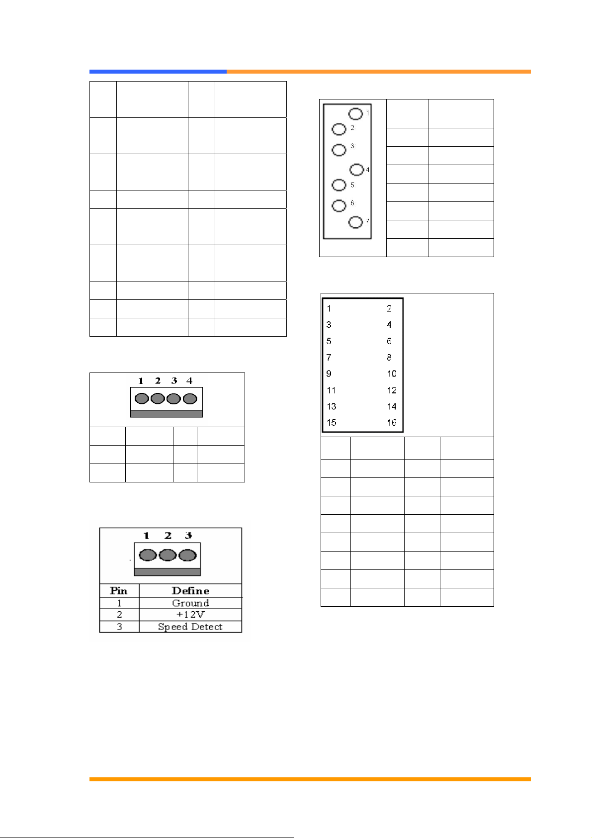
CN17, 18: SATA Connector
ID0#
109 AC_CODEC_
ID1#
111 MOD_AUDIO_
MOD
113 AUDIO_GND 114 GND
115 SYS_AUDIO_
OUT
117 SYS_AUDIO_
OUT G
119 AUDIO_GND 120 AUDIO_GND
121 RESERVED 122 MPCIACT#
123 VCC5VA 124 3.3VAUX
110 AC_RESET#
112 RESERVED
116 SYS_AUDIO_
IN
118 SYS_AUDIO_
IN G
CN15: IDE Power Connector
Pin Define
1 Ground
2 TXP
3 TXN
4 Ground
5 RXN
6 RXP
7 Ground
CN22: LAN LED Header
Pin Define Pin Define
1 +12V 2 GND
3 GND 4 +5V
CN16, 19, 20, 21: Fan Connector
Pin Define Pin Define
1 PRO 2 SPEED0
3 ACTIVE0 4 LINK0
5 RP1 6 SPEED1
7 ACTIVE1 8 LINK1
9 RP2 10 SPEED2
11 ACTIVE2 12 LINK2
13 RP3 14 SPEED3
15 ACTIVE3 16 LINK3
CN23: Manufacturing Default Using
Setting by manufacturer.
©2006 AEWIN Technologies Co., Ltd. All rights reserved. Ver 1.1. Aug, 2006
13
Page 14
User’s Manual
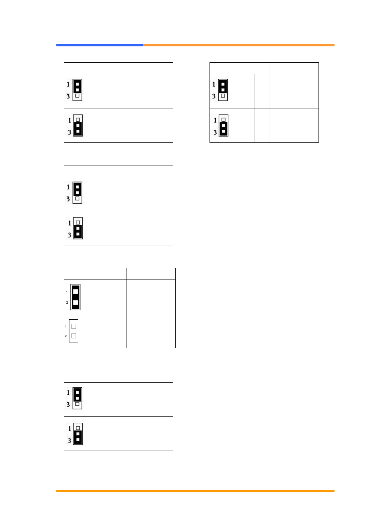
JP1: Bypass/Watch Dog Select
JP5: CPU FSB Select
Pin Setting
Bypass Mode
1-2
2-3 Watchdog
JP2: Bypass Mode Select
Pin Setting
Bypass Always
1-2
2-3
Pin Setting
1-2 533MHz
(Default)
2-3 400MHz
Enabled
Normal
(Default)
JP3: CF Master/Slave Select
Pin Setting
Close Master
Open Slave
JP4: Clear CMOS
Pin Setting
1-2
Hold Data
(Default)
2-3 Clear CMOS
©2006 AEWIN Technologies Co., Ltd. All rights reserved. Ver 1.1. Aug, 2006
14
Page 15

User’s Manual
2.4 CompactFlashTM Socket Pin Assignment
CompactFlashTM card is a small removable mass storage device. It can provide
complete PCMCIA-ATA functionality and compatibility plus True IDE functionality
compatible with ATA/ATAPI-4.
CompactFlashTM storage products are solid state form factor, it means they contain
no moving parts. Thus, it provides users with much greater protection of the data
than conventional magnetic disk device.
Pin Assignment Pin Assignment Pin Assignment Pin Assignment Pin Assignment
1 Ground 11 Ground 21 D00 31 D15 41 RESET
2 D03 12 Ground 22 D01 32 CS 42 ORDY
3 D04 13 VCC 23 D02 33 NC 43 DREG
4 D05 14 Ground 24 WP 34 IOR 44 DACK
5 D06 15 Ground 25 NC 35 IOW 45 LED
6 D07 16 Ground 26 NC 36 WE 46 BVD
7 CS 17 Ground 27 D11 37 RDY/BSY 47 D08
8 Ground 18 A02 28 D12 38 VCC 48 D09
9 Ground 19 A01 29 D13 39 SCSE 49 D10
10 Ground 20 A00 30 D14 40 NC 50 Ground
©2006 AEWIN Technologies Co., Ltd. All rights reserved. Ver 1.1. Aug, 2006
15
Page 16

User’s Manual
Chapter 3. BIOS Setup
The ROM chip of your CB-6970 board is configured with a customized Basic
Input/Output System (BIOS) from Phoenix-Award BIOS. The BIOS is a set of
permanently recorded program routines that give the system its fundamental
operational characteristics. It also tests the computer and determines how the
computer reacts to instructions that are part of programs.
The BIOS is made up of code and programs that provide the device-level control for
the major I/O devices in the system. It contains a set of routines (called POST, for
Power-On Self Test) that check out the system when you turn it on. The BIOS also
includes CMOS Setup program, so no disk-based setup program is required CMOS
RAM stores information for:
z Date and time
z Memory capacity of the main board
z Type of display adapter installed
z Number and type of disk drives
The CMOS memory is maintained by battery installed on the CB-6970 board. By
using the battery, all memory in CMOS can be retained when the system power
switch is turned off. The system BIOS also supports easy way to reload the CMOS
data when you replace the battery of the battery power lose.
3.1 Quick Setup
In most cases, you can quickly configure the system by choosing the following main
menu options:
1. Choose “Load Optimized Defaults” from the main menu. This loads the setup
default values from the BIOS Features Setup and Chipset Features Setup
screens.
2. Choose “Standard COS Features” from the main menu. This option lets you
configure the date and time, hard disk type, floppy disk drive type, primary
display and more.
3. In the main menu, press F10 (“Save & Exit Setup”) to save your changes and
reboot the system.
©2006 AEWIN Technologies Co., Ltd. All rights reserved. Ver 1.1. Aug, 2006
16
Page 17
User’s Manual
3.2 Entering the CMOS Setup Program
Use the CMOS Setup program to modify the system parameters to reflect the
options installed in your system and to customize your system. For example, you
should run the Setup program after you:
z Received an error code at startup
z Install another disk drive
z Use your system after not having used it for a long time
z Find the original setup missing
z Replace the battery
z Change to a different type of CPU
z Run the Phoenix-Award Flash program to update the system BIOS
Run the CMOS Setup program after you turn on the system. On-screen
instructions explain how to use the program.
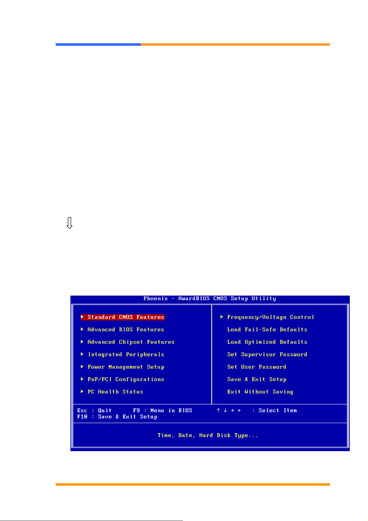
Enter the CMOS Setup program’s main menu as follows:
1. Turn on or reboot the system. After the BIOS performs a series of
diagnostic checks, the following message appears:
“Press DEL to enter SETUP”
2. Press the <DEL> key to enter CMOS Setup program. The main menu
appears:
©2006 AEWIN Technologies Co., Ltd. All rights reserved. Ver 1.1. Aug, 2006
17
Page 18

User’s Manual
3. Choose a setup option with the arrow keys and press <Enter>. See the
following sections for a brief description of each setup option.
In the main menu, press F10 (“Save & Exit Setup) to save your changes and
reboot the system. Choosing “EXIT WITHOUT SAVING” ignores your
changes and exits the program. Pressing <ESC> anywhere in the program
returns you to the main menu.
3.3 Menu Options
The main menu options of the CMOS Setup program are described in the following
and the following sections of this chapter.
STANDARD CMOS FEATURES:
Configure the date & time, hard disk drive type, floppy disk drive type, primary
display type and more
ADVANCED BIOS FEATURES:
Configure advanced system options such as enabling/disabling cache memory and
shadow RAM
ADVANCED CHIPSET FEATURES:
Configure advanced chipset register options such DRAM timing
INTEGRATED PERIPHERALS:
Configure onboard I/O functions
POWER MANAGEMENT SETUP:
Configure power management features such as timer selects
PNP/PCI CONFIGURATION:
Configure Plug & Play IRQ assignments and PCI slots
PC HEALTH STATUS:
Configure the CPU speed and, if the optional system monitor IC is installed, view
system information
FREQUENCY / VOLTAGE CONTROL:
Configure the CPU and PCI clock, if the optional system monitor IC is installed, view
system information
©2006 AEWIN Technologies Co., Ltd. All rights reserved. Ver 1.1. Aug, 2006
18
Page 19
User’s Manual
LOAD FAIL-SAFE DEFAULT:
Loads BIOS default values. Use this option as diagnostic aid if your system
behaves erratically
LOAD OPTIMIZED DEFAULTS:
Loads optimized BIOS settings
SET SUPERVISORS & USER PASSWORD:
Configure the system so that a password is required when the system boots or you
attempt to enter the CMOS setup program. When you log in with this password,
you will be able to enter the CMOS Setup main menu, but you can not enter other
menus in the CMOS Setup program.
SAVE & EXIT SETUP:
Save changes of values to CMOS and exit the CMOS setup program
EXIT WITHOUT SAVING:
Abandon all CMOS changes and exit the CMOS setup program
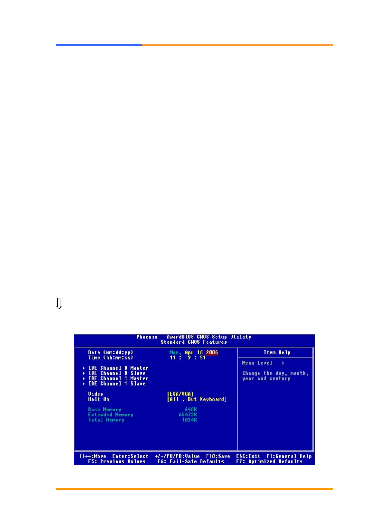
3.4 Standard CMOS Features Setup
Use the Standard CMOS Setup option as follows:
1. Choose “Standard CMOS Features” from the main menu. The following screen
appears:
2. Use the arrow keys to move between fields. Modify the selected field using the
©2006 AEWIN Technologies Co., Ltd. All rights reserved. Ver 1.1. Aug, 2006
19
Page 20

User’s Manual
PgUP/PgDN/+/- keys. Some fields let you enter numeric values directly.
Option Description
Date (mm:dd:yy) Type the current date
Time
(hour:min:sec)
IDE channel Select from “Auto”, “User”, or “None”
Video Select the default video device: EGA/VGA, CGA 40, CGA 80,
Halt On Select the situation what you want BIOS to stop power on self
3. After you have finished with the Standard CMOS Features program, press the
Type the current time (24-hour clock)
If your drive is not one of the predefined types, choose “User”
and enter the following drive specifications:
Cylinders, heads, Wpcom, L-Zone, sectors, and mode
Consult the documentation received with the drive for the values
that will give you optimum performance.
Mono
test process and notice you.
Choose: <All Errors> <No Errors/ All> <But Keyboard (Default)>
<All, But Diskette> <All, But Disk/Key>
<ESC> key to return to the main menu.
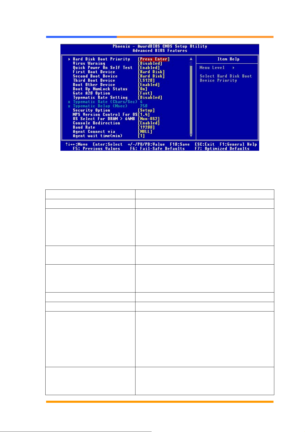
3.5 Advanced BIOS Features Setup
Use the Advanced BIOS Features Setup option as follows:
1. Choose “Advanced BIOS Features Setup” from the main menu. The following
screen appears:
©2006 AEWIN Technologies Co., Ltd. All rights reserved. Ver 1.1. Aug, 2006
20
Page 21
User’s Manual
2. Use the arrow keys to move between items and to select values. Modify the
selected fields using the PgUP/PgDN keys. Press the <F1> “Help” key for
information on the available options:
Option Description
Hard Disk Boot Priority Set up the hard disk boot sequence.
Virus Warning When enabled, anything attempts to access the
boot sector and partition table, the BIOS will show
a warning message on screen and alarm beep.
The default setting is Disabled.
Quick Power On Self Test Skip some checking items and speed up the power
on process.
First/Second/Third Boot Device The BIOS attempts to load the operating system
from the devices in the sequence selected in these
items. Choose: HDD-0, LS-120, USB FDD…..
Boot Other Device Set up other device to be bootable.
Boot Up NumLock Status Select power on status of NumLock.
Gate A20 Option Gate A20 is a device used to address memory
above 1 MB.
Fast (Default): Select chipset controller to control
Gate 20.
Normal: Select Keyboard controller to control Gate
20.
Typematic Rate Setting The rate to click the keyboard is defined by
keyboard controller. When enabled, you can
configure the Typematic Rate and Typematic
©2006 AEWIN Technologies Co., Ltd. All rights reserved. Ver 1.1. Aug, 2006
21
Page 22

User’s Manual
Delay. The default is Disabled.
X Typematic Rate: Set the rate keyboard can
repeat per second, from 6~30 char/sec.
X Typematic Delay: Set the delay time before
keyboard can repeat, from 250~1000ms.
Security Option Select whether the password is required for
system boot or enter Setup menu.
X System: the system will not boot and not access
Setup menu if the password is wrong.
X Setup: the system can boot, but not allow to
access Setup menu if the password is wrong.
MPS Version Control For OS Select 1.1, 1.4. Default is 1.4.
OS Select for DRAM > 64MB Select OS/2 if your system is using OS/2 and has
a memory size of more than 64MB. Default is
Non-OS2.
Console Redirection Choose <enabled> allowing connecting the server
of hyper terminal to monitor client side. It has to
be worked under DOS mode, and the client
terminal doesn’t need graphic function.
Baud Rate The data transfer rate (bit per second) to agent.
Choose 9600/19200/38400/57600/115200 item.
Agent Connect via Select <Null> to let agent connect directly.
Agent wait time (min) Agent negotiate time, choose 1/2/4/8 min.
Agent after boot Choose <enabled> for agent to administrate the
system after boot.
Video BIOS Shadow Choose <Enabled> to change the Video BIOS
location from ROM to RAM. Video shadow will
enhance the Video speed.
Full Screen Logo Show Allow to display the full screen logo when boot up.
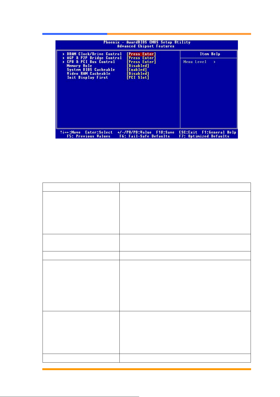
3.6 Advanced Chipset Features Setup
Use the Advanced Chipset Features Setup option as follows:
1. Choose “Advanced Chipset Features Setup” from the main menu. The
following screen appears;
©2006 AEWIN Technologies Co., Ltd. All rights reserved. Ver 1.1. Aug, 2006
22
Page 23
User’s Manual
2. Move between items and select values by using the arrow keys. Modify the
selected fields using the PnUP/PgDN Keys. For information on the various options,
press
<F1> key .
Option Description
DRAM Clock/Device Control Select <By SPD> or <Auto By SPD> to follow PC
SDRAM Serial Presence Detect Specification.
DRAM Clock <By SPD>
DRAM Timing < Auto By SPD>
AGP & P2P Bridge Control Allow to allocate the system resource to AGP for
video use.
CPU & PCI Bus Control Allow to setup the ability for CPU and PCI bus.
Memory Hole Select Enabled or Disabled. You can reserve this
area of system memory for ISA adapter ROM.
When this area is reserved, it can not be cached.
The user information of peripherals that need to use
this area of system memory usually discusses their
memory requirement.
System BIOS Cacheable Select Enabled or Disabled. When enabled,
caching of the system BIOS at F0000h-FFFFFh,
enhancing system performance. However, if any
program writes to this memory area, a system error
may result.
Video RAM Cacheable Select Enabled or Disabled. When Enable this
©2006 AEWIN Technologies Co., Ltd. All rights reserved. Ver 1.1. Aug, 2006
23
Page 24
User’s Manual
option to allow caching of the Video BIOS.
Init Display First Allow to choose the priority of PCI VGA card or
onboard. Default is <PCI slot>.
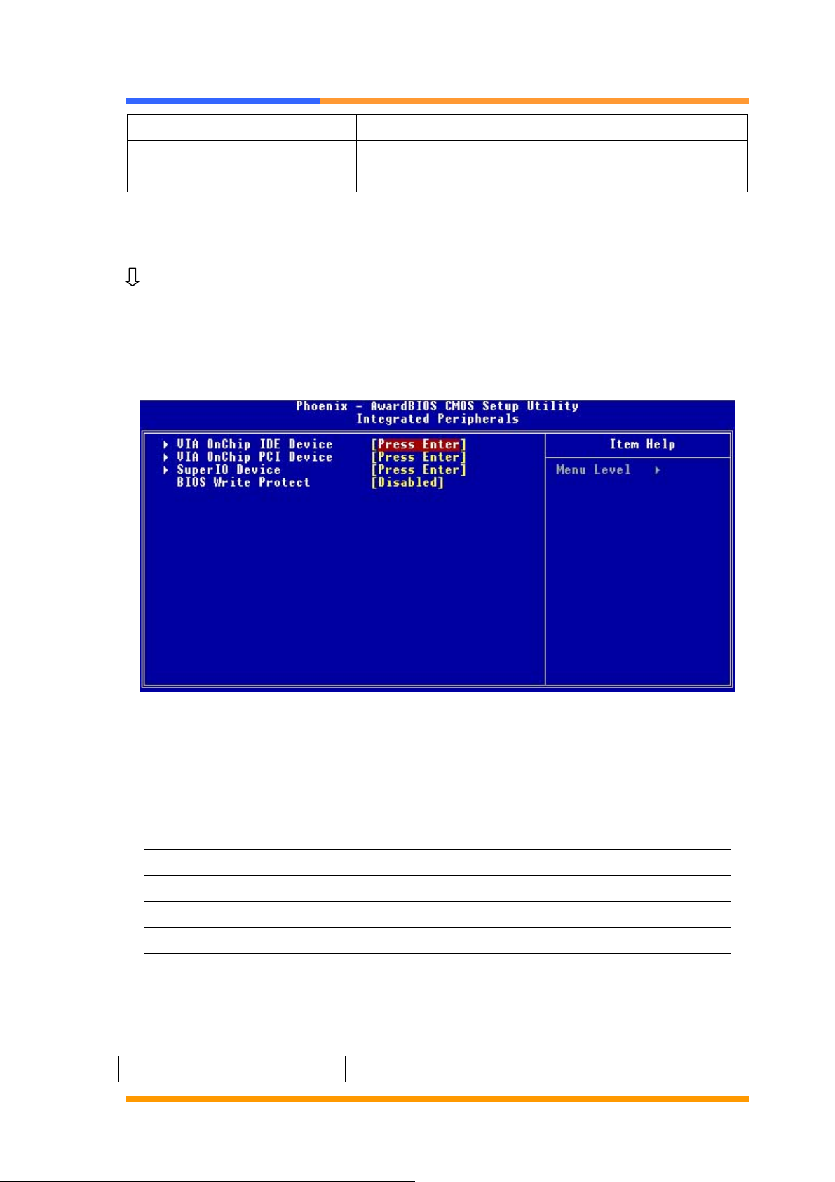
3.7 Integrated Peripherals
Use the Integrated Peripherals Setup option as follows:
1. Choose “Integrated Peripherals Setup” from the main menu. The following
screen appears:
2. Move between items and select values by using the arrow keys. Modify the
selected fields using the PgUP/PgDN keys. Please press the <F1> key for
information on the various options.
Option Description
Onboard Device
VIA OnChip IDE Device Select and set up the SATA, IDE devices
VIA OnChip PCI Device Select and set up the PCI devices
Super I/O Device Select and set up the super I/O devices
BIOS Write Protect <Enabled> not allow to write data into BIOS. The
default is <Disabled>.
Super IO Device
Onboard Serial Port 1
3F8/IRQ4、2F8/IRQ3、3E8/IRQ4、2E8/IRQ3、AUTO
©2006 AEWIN Technologies Co., Ltd. All rights reserved. Ver 1.1. Aug, 2006
24
Page 25
User’s Manual
Onboard Serial Port 2
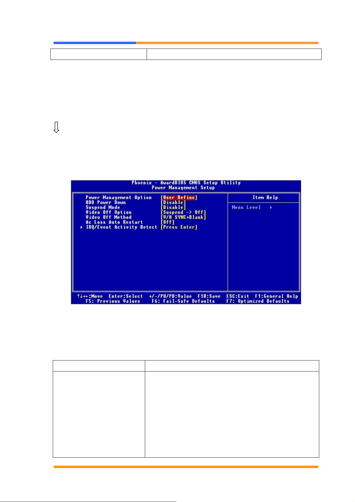
3.8 Power Management Setup
The Power Management Setup controls the board’s “green” features. To save
energy these features shut down the video display and hard disk drive.
Use the Power Management Setup option as follows:
1. Choose “Power Management Setup” from the main menu. The following screen
appears.
3F8/IRQ4、2F8/IRQ3、3E8/IRQ4、2E8/IRQ3、AUTO
2. Move between items and select values by using the arrow keys. Modify the
selected field the PgUP/PgDN keys. For information on the various options,
press <F1> key.
Option Description
Power Management Option This field allows you to select the type (or degree) of
power saving by changing the length of idle time that
elapses before the “Suspend Mode” and “HDD Power
Down” field is activated. Min Saving Minimum power
saving time for the “ Suspend Mode” and “HDD Power
Down” =15min.
Max Saving Maximum power saving time for the
“Suspend Mode” and “HDD Power Down”=1 min.
©2006 AEWIN Technologies Co., Ltd. All rights reserved. Ver 1.1. Aug, 2006
25
Page 26

User’s Manual
User Define Allows you to set the power saving time in
the “Suspend Mode” and “HDD Power Down” field.
HDD Power Down This is selectable only when the power management
filed is set to user define. When the system enters the
HDD power down mode according to the power saving
time selected, the hard disk drive will be powered
down while all other devices remain active.
Suspend Mode When the system enters the Suspend mode, the CPU
and onboard peripherals will be shut off.
Video Off Option Select power saving modes when the monitor is blank.
Default is <Suspend - > Off>.
Video Off Method This determines the manner in which the monitor is
blanked. V/H SYNC + Blank This selection will cause
the system to turn off the vertical and horizontal
synchronization ports and write blanks to the video
buffer.
Ac Loss Au to Restart The field defines how the system will act after an AC
power loss during system. Select <Off> will keep the
system in off status until press the power button.
Select <On> will automatically power on when AC
power is back.
IRQ/Event Activities Detect Allow to set IRQs that will reestablish the system from
a power saving sleep mode.
3. After you have finished with the Power Management Setup, press the <ESC>
key to return to the main menu.
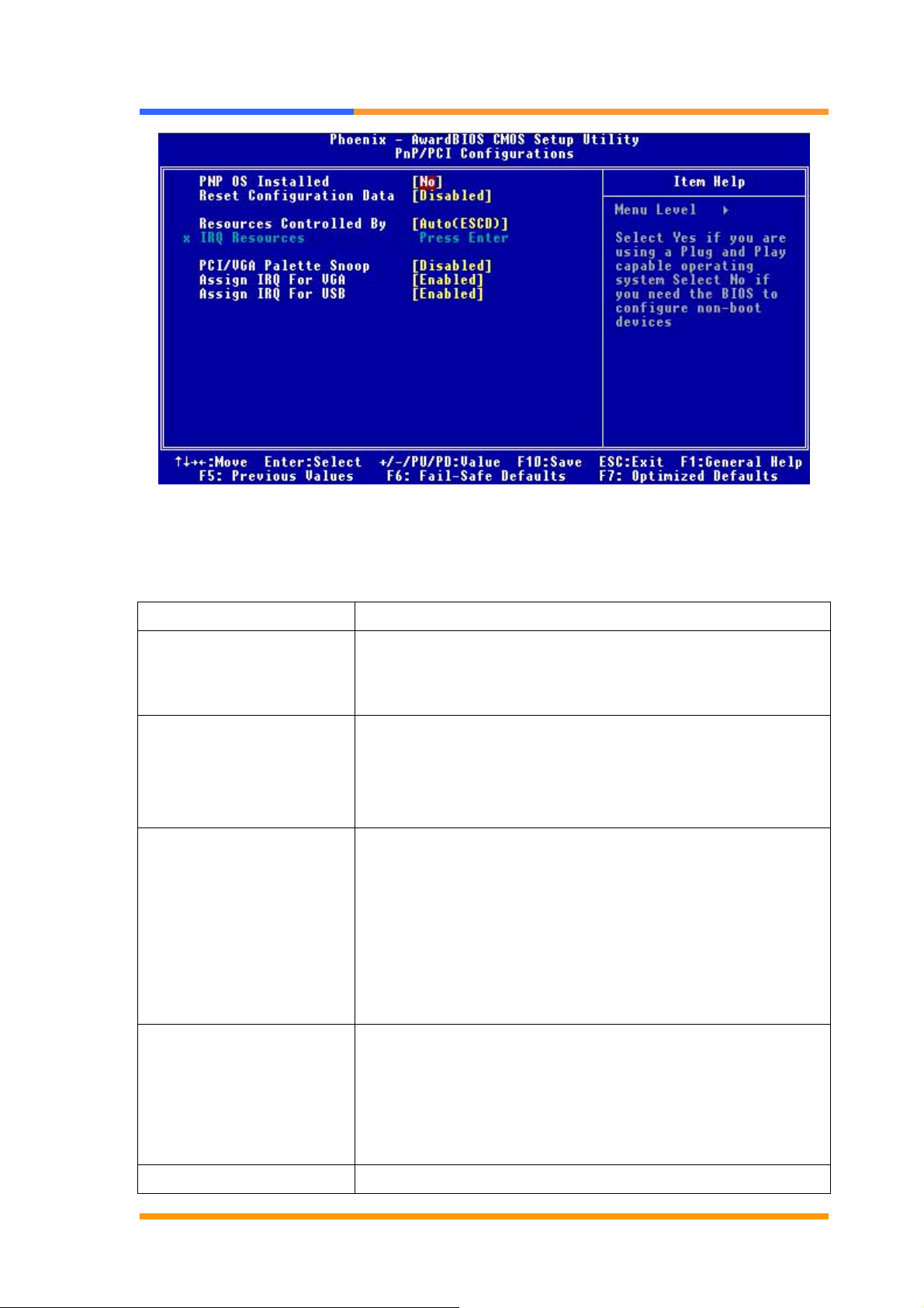
3.9 PNP/PCI Configuration
This option is used to configure Plug and Play assignments and route PCI interrupts
to designated ISA interrupts.
Use the PNP/PCI Configuration Setup option as follows:
1. Choose “PNP/PCI Configuration Setup” from the main menu, the following
screen appears.
©2006 AEWIN Technologies Co., Ltd. All rights reserved. Ver 1.1. Aug, 2006
26
Page 27
User’s Manual
2. Move between items and select values by using the arrow keys. Modify the
selected fields using the PgUP/PgDN keys. For information on the various
options, please press <F1> key.
Option Description
PNP OS installed NO: BIOS program will adjust all the set up by itself
YES: When you install the system that support plug &
play, press <YES>
Reset Configuration Data Enabled The BIOS will reset the Extended System
Configuration Data (ESCD) once automatically. It will
then recreate a new set of configure data
Disabled The BIOS will not reset the configuration data
Resources Controlled By Resources controlled by the Award plug and play BIOS
has the capability to automatically configure all of the
boot and plug and play compatible devices.
Auto (ESCD) The system will automatically detect the
settings for you.
Manual choose the specific IRQ in the “ IRQ Resources”
field.
PCI/VGA Palette Snoop This field determines whether the MPEG ISA/VESA VGA
cards a work with PCI/VGA or not
Enable MEPG ISA/VESA VGA cards work with PCI/VGA
Disabled MPEG ISA/VESA VGA card does not work with
PCI/VGA
Assign IRQ for VGA Select Enabled/Disabled to specify whether the VGA
©2006 AEWIN Technologies Co., Ltd. All rights reserved. Ver 1.1. Aug, 2006
27
Page 28
User’s Manual
uses on IRQ or not.
Assign IRQ for USB Select Enabled/Disabled to specify whether the USB
uses on IRQ or not.
3. Please press the <ESC> key to return the main menu after finishing with the
PNP/PCI Configuration Setup.
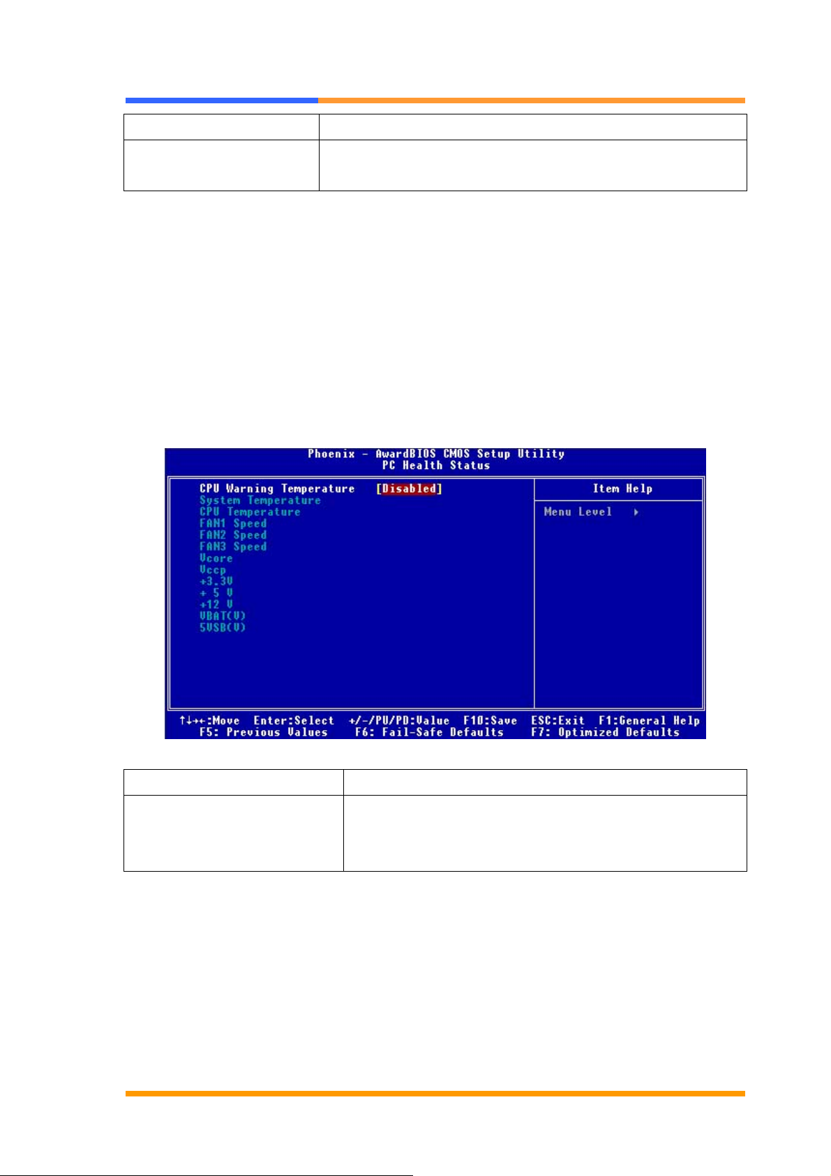
3.10 PC Health Status Configuration Setup
Choose “PC Health Status Configuration Setup” from the main menu, the following
screen appears:
Option Description
CPU Warning Temperature An alarm will beep when the CPU temperature is
higher than the maximum limit. The default is
<Disabled> and alarm will not beep.
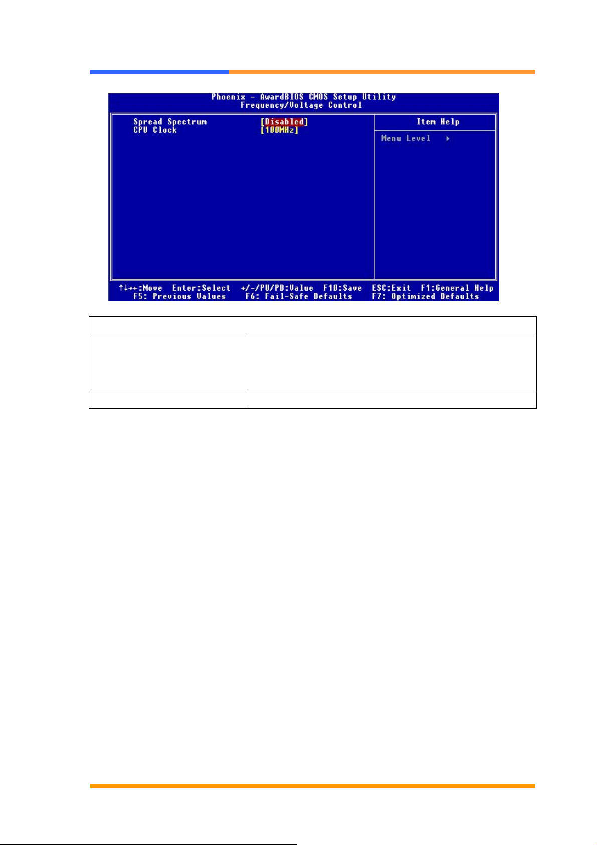
3.11 Frequency/Voltage Control
The item enabled you to set up the clock speed and system bus for your system.
The clock speed and system bus are determined by the kind of processor you have
installed in the system.
©2006 AEWIN Technologies Co., Ltd. All rights reserved. Ver 1.1. Aug, 2006
28
Page 29
User’s Manual
Option Description
Spread Spectrum If you enable the item, it can significantly reduce the
EMI (Electro-Magnetic Interference) generated by the
system.
CPU Clock Allow to adjust the CPU Clock.
3.12 Load Fail-Safe Defaults
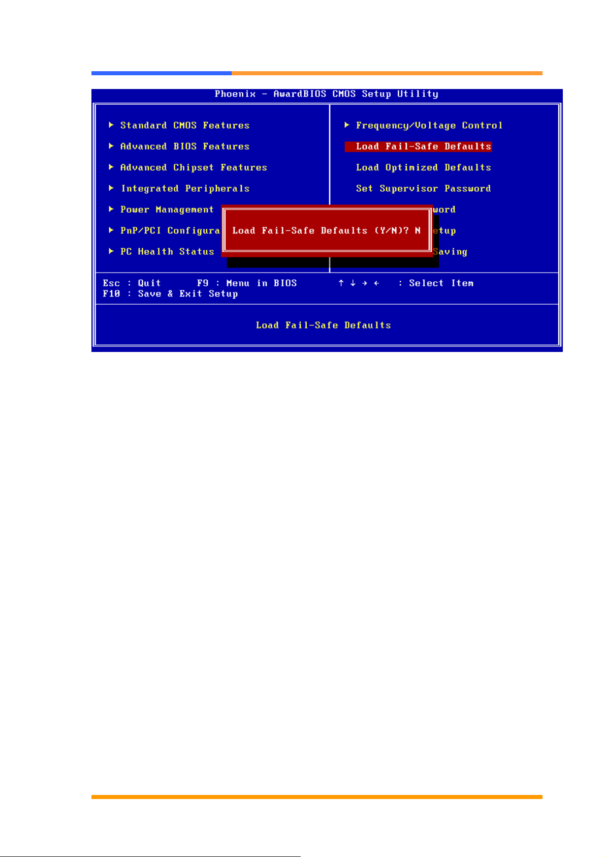
This option loads the troubleshooting default values permanently stored in the BIOS
ROM. This is useful if you are having problems with the main board and need to
debug or troubleshoot the system. The loaded default settings do not affect the
Standard CMOS Setup screen.
©2006 AEWIN Technologies Co., Ltd. All rights reserved. Ver 1.1. Aug, 2006
29
Page 30
User’s Manual
To use this feature, highlight it on the main screen and press <Enter>. A line will
appear on the screen asking if you want to load the BIOS default values. Pres the
<Y> key and then press <Enter> if you want to load the BIOS default.
3.13 Load Optimized Defaults
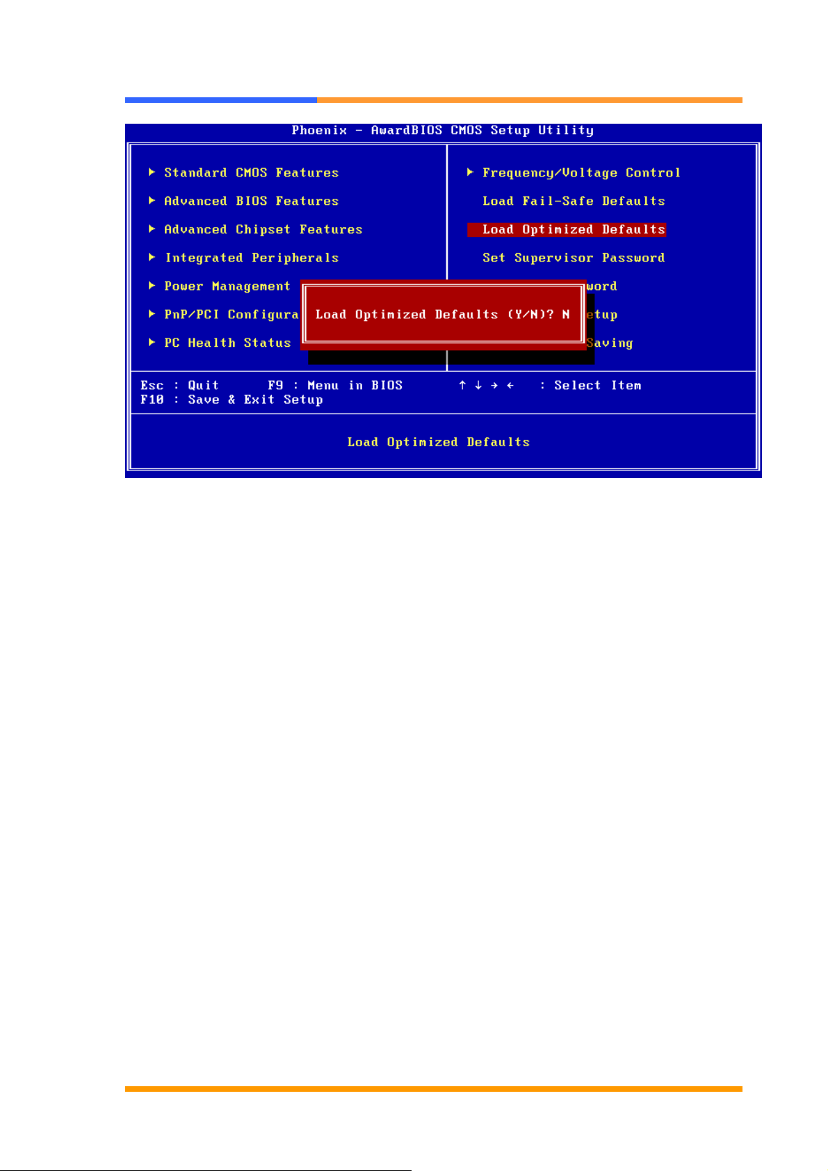
This option loads optimized settings stored in the BIOS ROM. The auto-configured
settings do not affect the Standard CMOS Setup screen.
©2006 AEWIN Technologies Co., Ltd. All rights reserved. Ver 1.1. Aug, 2006
30
Page 31
User’s Manual
To use this feature, highlight it on the main screen and press <Enter>. A line will
appear on the screen asking if you want to load the Optimized Default Values.
Press the <Y> key and then press <Enter> if you want to load the SETUP default.
3.14 Supervisor/User Password
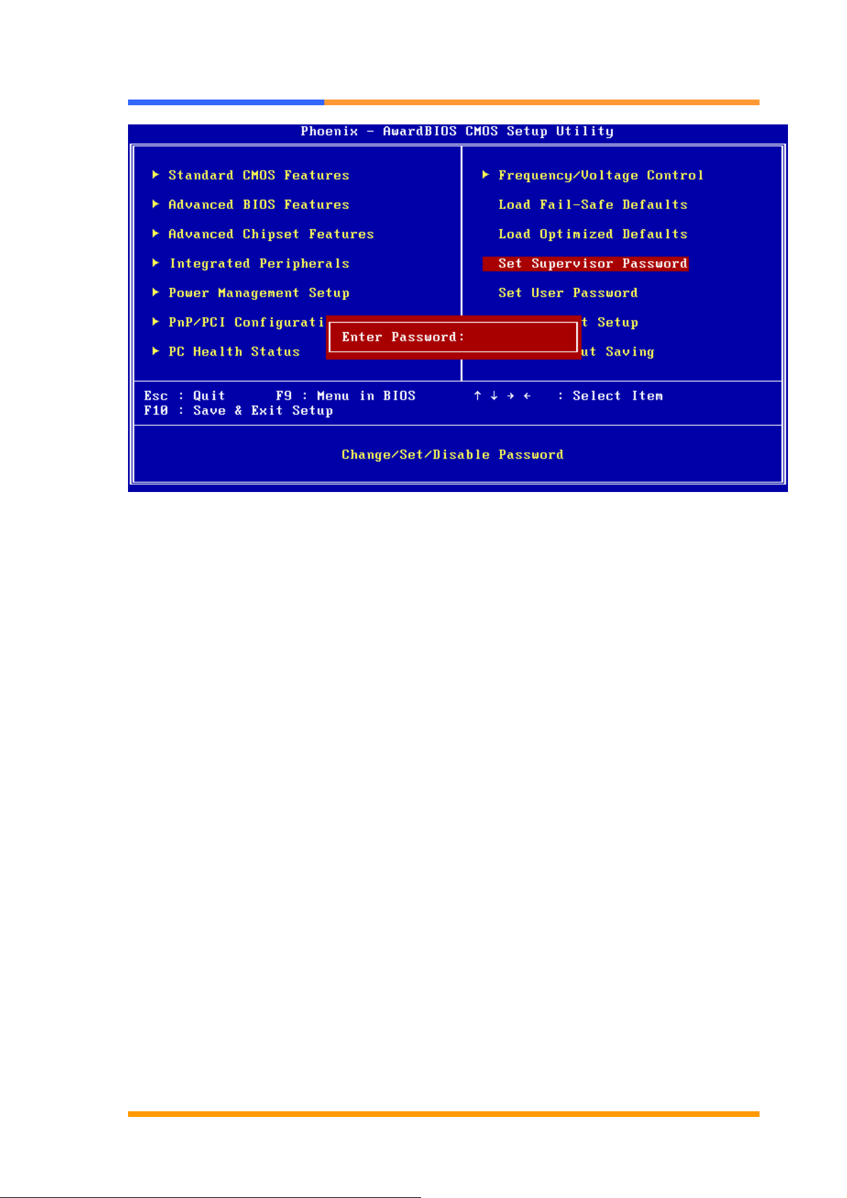
The password options let you prevent unauthorized system boot-up or unauthorized
use of CMOS setup. The Supervisor Password allows both system and CMOS
Setup program access; the User Password allows access to the system and the
CMOS Setup Utility main menu.
The password functions are disabled by default. You can use these options to
enable a password function or, if a password function is already enabled, change
the password.
To change a password, first choose a password option from the main menu and
enter the current password. Then type your new password at the prompt. The
password is case sensitive and you can use up to 8 alphanumeric characters.
Press <Enter> after entering the password. At the Next Prompt, confirm the new
password by typing it and pressing <Enter> again.
©2006 AEWIN Technologies Co., Ltd. All rights reserved. Ver 1.1. Aug, 2006
31
Page 32
User’s Manual
After you use this option to enable a password function, use the “Security Option” in
“BIOS Feature Setup” to specify whether a password is required every time the
system boots or only when an attempt is made to enter the CMOS Setup program.
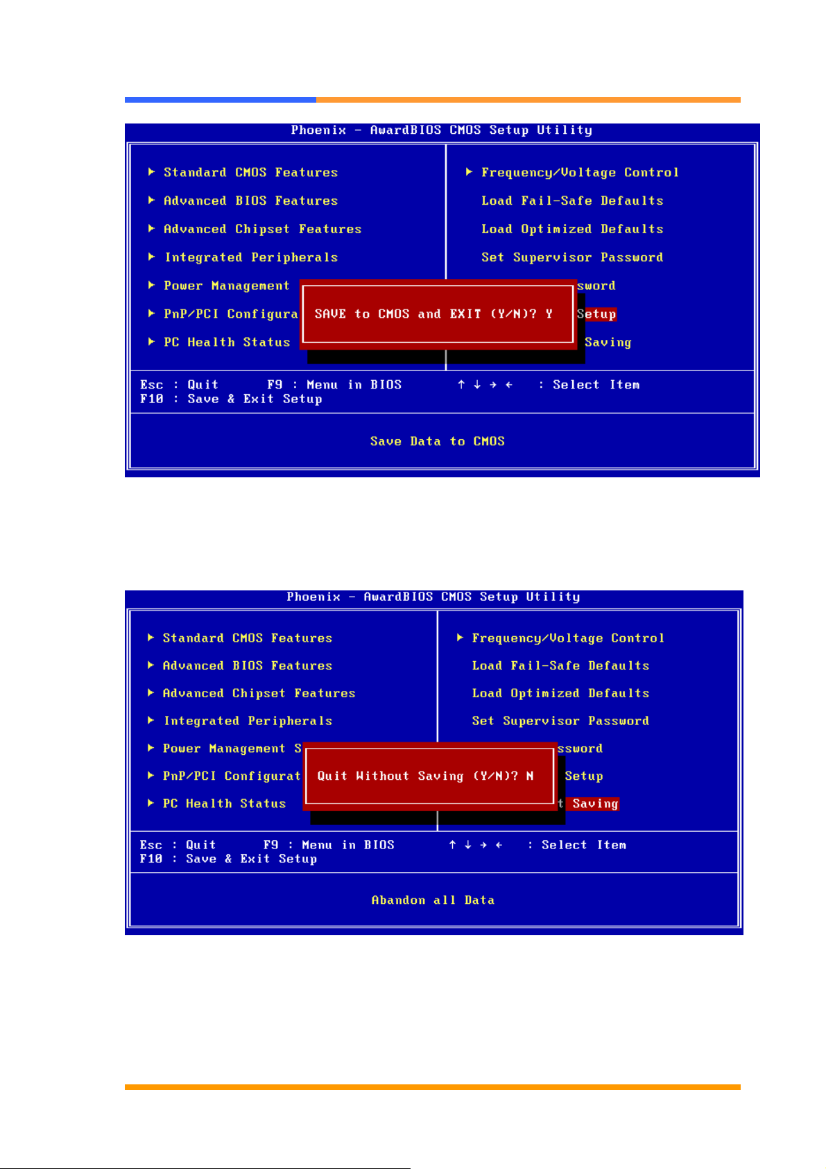
3.15 Save and Exit Setup
This function automatically saves all CMOS values before exiting Setup.
©2006 AEWIN Technologies Co., Ltd. All rights reserved. Ver 1.1. Aug, 2006
32
Page 33
User’s Manual
3.16 Exit Without Saving
Use this function to exit Setup without saving the CMOS value.
©2006 AEWIN Technologies Co., Ltd. All rights reserved. Ver 1.1. Aug, 2006
33
Page 34
User’s Manual
Chapter 4. Utility & Driver Installation
4.1 Operation System Supporting
CB-6970 can support Windows® and Linux® operation system as follows. Before
installation, please check your OS version. If your OS is not in the following list, please
upgrade your OS version.
OS Version
Windows® Windows® 2000 SP4/Windows® XP SP2
Linux® Fedora Core 2/Linux® 2.6 or above
4.2 System Driver Installation
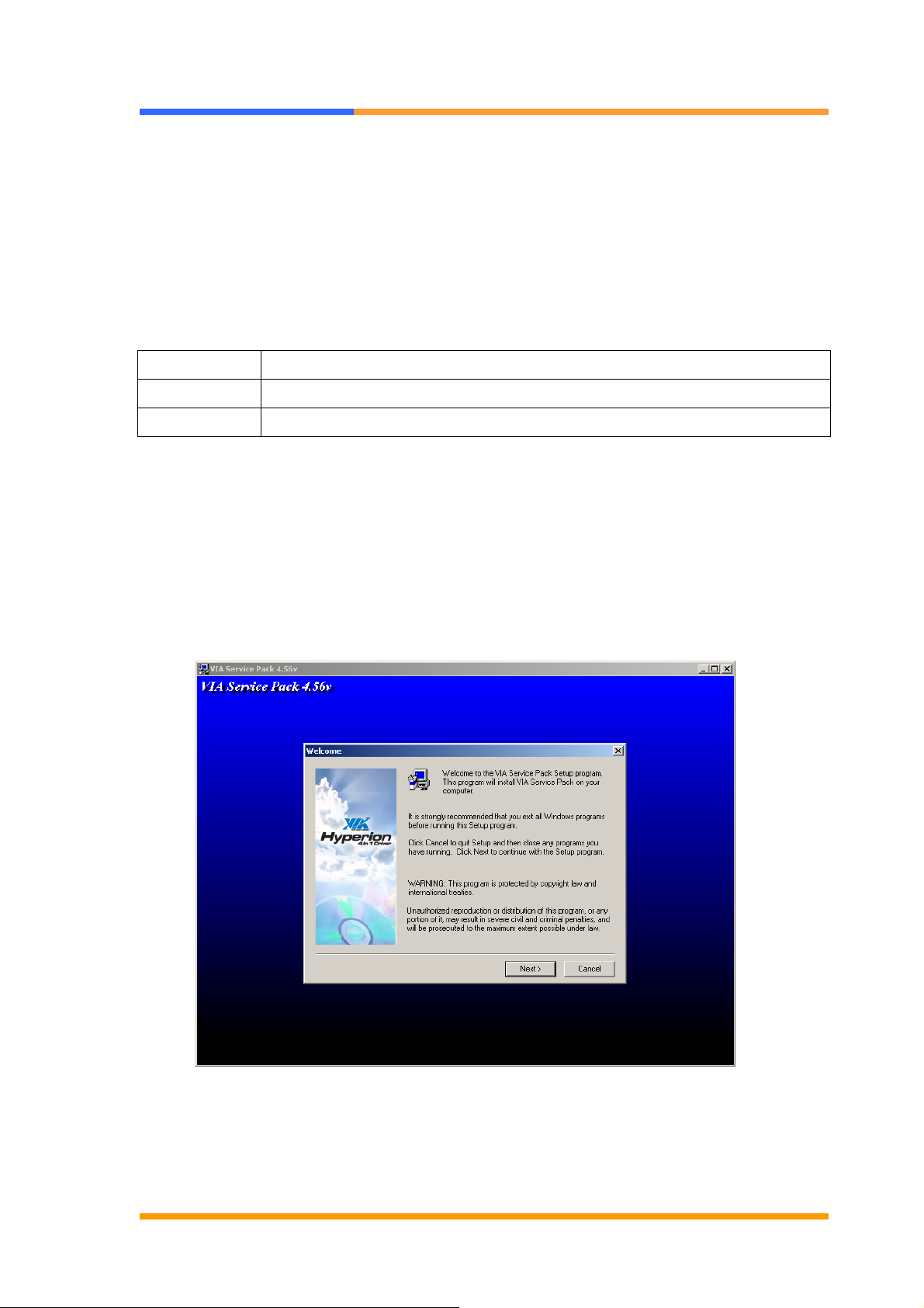
CB-6970 offers the system driver in the setup CD. Please install the driver follow the
below procedures.
1. Insert the setup CD of CB-6970 into your CD-ROM drive.
2. Choose the Drivers/system file to click the Setup icon.
3. Click [Next] button.
©2006 AEWIN Technologies Co., Ltd. All rights reserved. Ver 1.1. Aug, 2006
34
Page 35
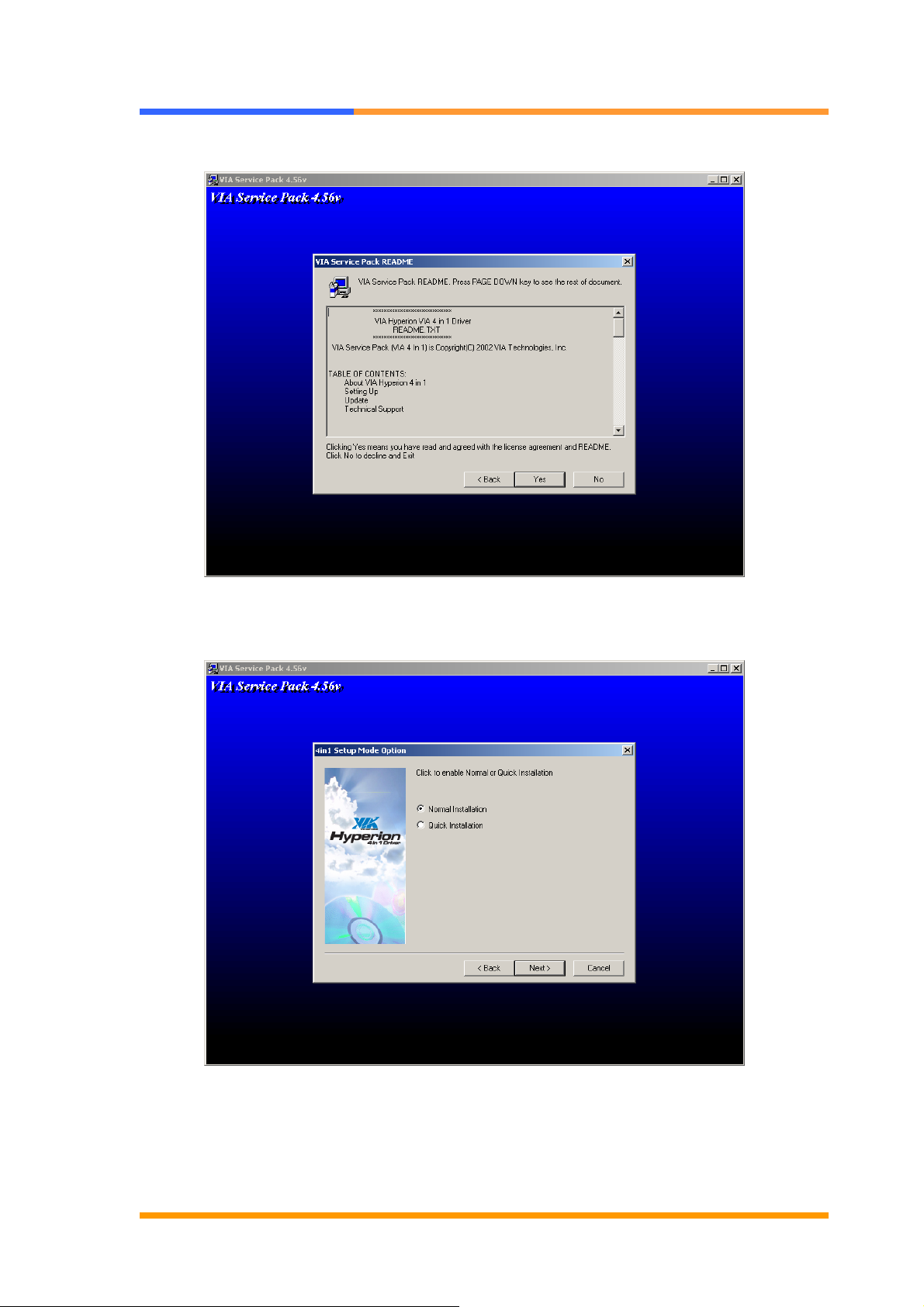
4 Click [YES] button.
User’s Manual
5. Choose <Normal Installation> to install all drivers. Click [Next] button.
©2006 AEWIN Technologies Co., Ltd. All rights reserved. Ver 1.1. Aug, 2006
35
Page 36
User’s Manual
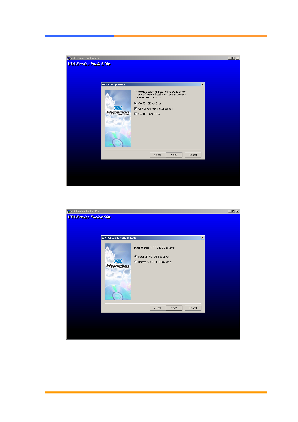
6. Choose all setting. Click [Next] button.
7. Choose <Install VIA PCI IDE Bus Driver>. Click [Next] button.
©2006 AEWIN Technologies Co., Ltd. All rights reserved. Ver 1.1. Aug, 2006
36
Page 37
User’s Manual
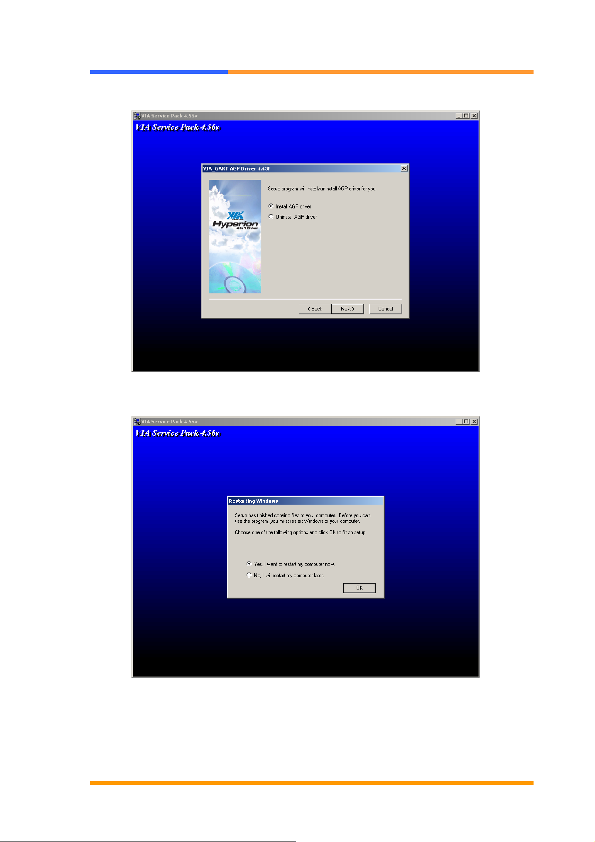
8. Choose <Install AGP driver>. Click [Next] button.
9. Click [OK] button to finish the installation.
©2006 AEWIN Technologies Co., Ltd. All rights reserved. Ver 1.1. Aug, 2006
37
Page 38
User’s Manual
4.3 LAN Driver Installation
CB-6970 support Ethernet controlled by using Intel 82551ER® or Realtek® 8139CL+
chipset. Please install the driver follow the below procedures.
1. Insert the setup CD of CB-6970 into your CD-ROM drive.
3. Click the [Start] button.
4. Choose the [Setting] item.
5. Click the [Control Panel] item.
6. Select the [Systems] item to open the [System Properties] box.
7. Click the [Device Manager] tab.
8. Choose the [Network adapters] item.
9. Click the [Driver] tab.
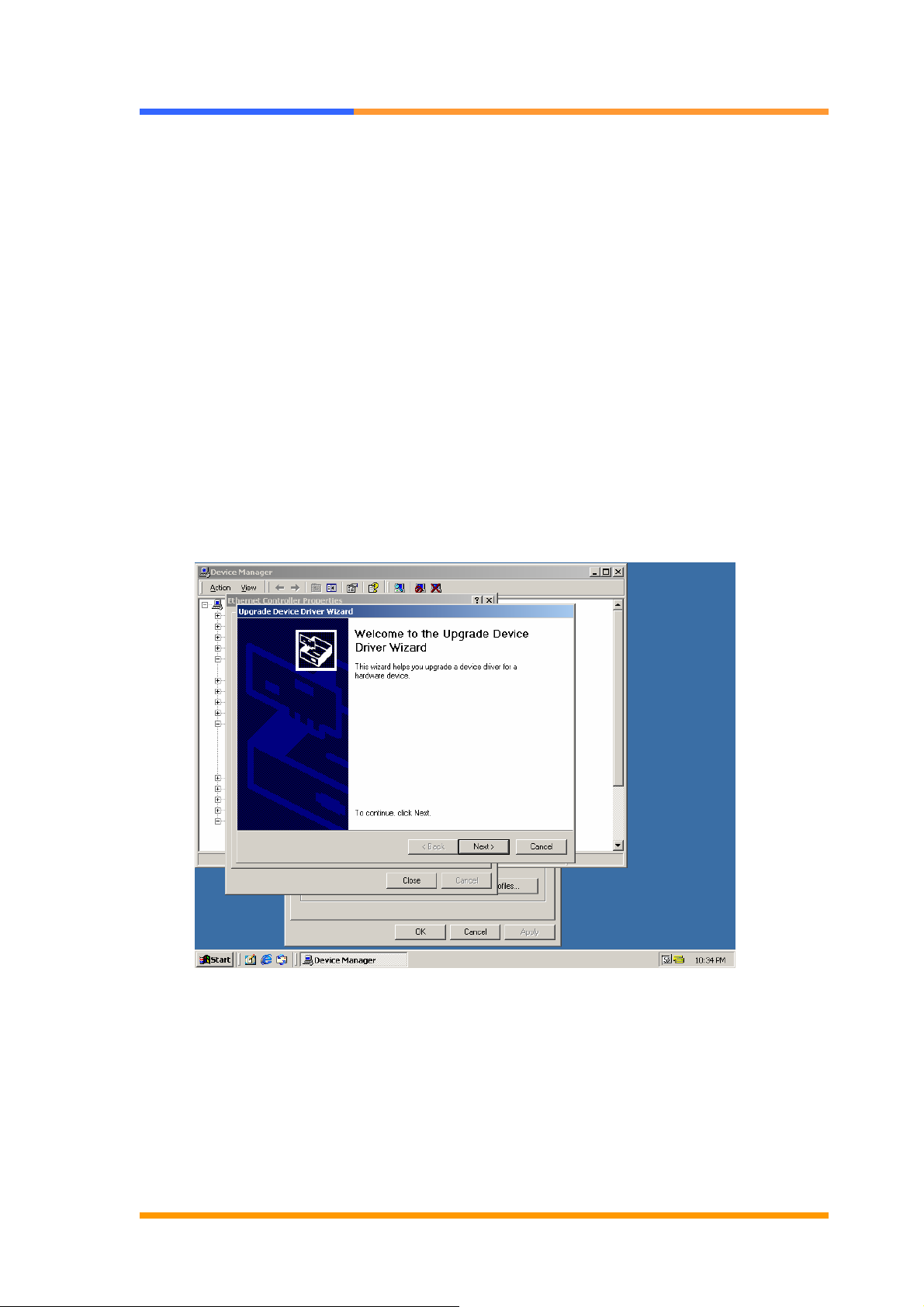
10. Click the [Update Driver] button. Then the Update Device Driver Wizard will appears.
11. Click [Next] button.
©2006 AEWIN Technologies Co., Ltd. All rights reserved. Ver 1.1. Aug, 2006
38
Page 39

12. Click [Next] button.
User’s Manual
13. Choose <Specify a location>, press [Next] button.
©2006 AEWIN Technologies Co., Ltd. All rights reserved. Ver 1.1. Aug, 2006
39
Page 40
User’s Manual
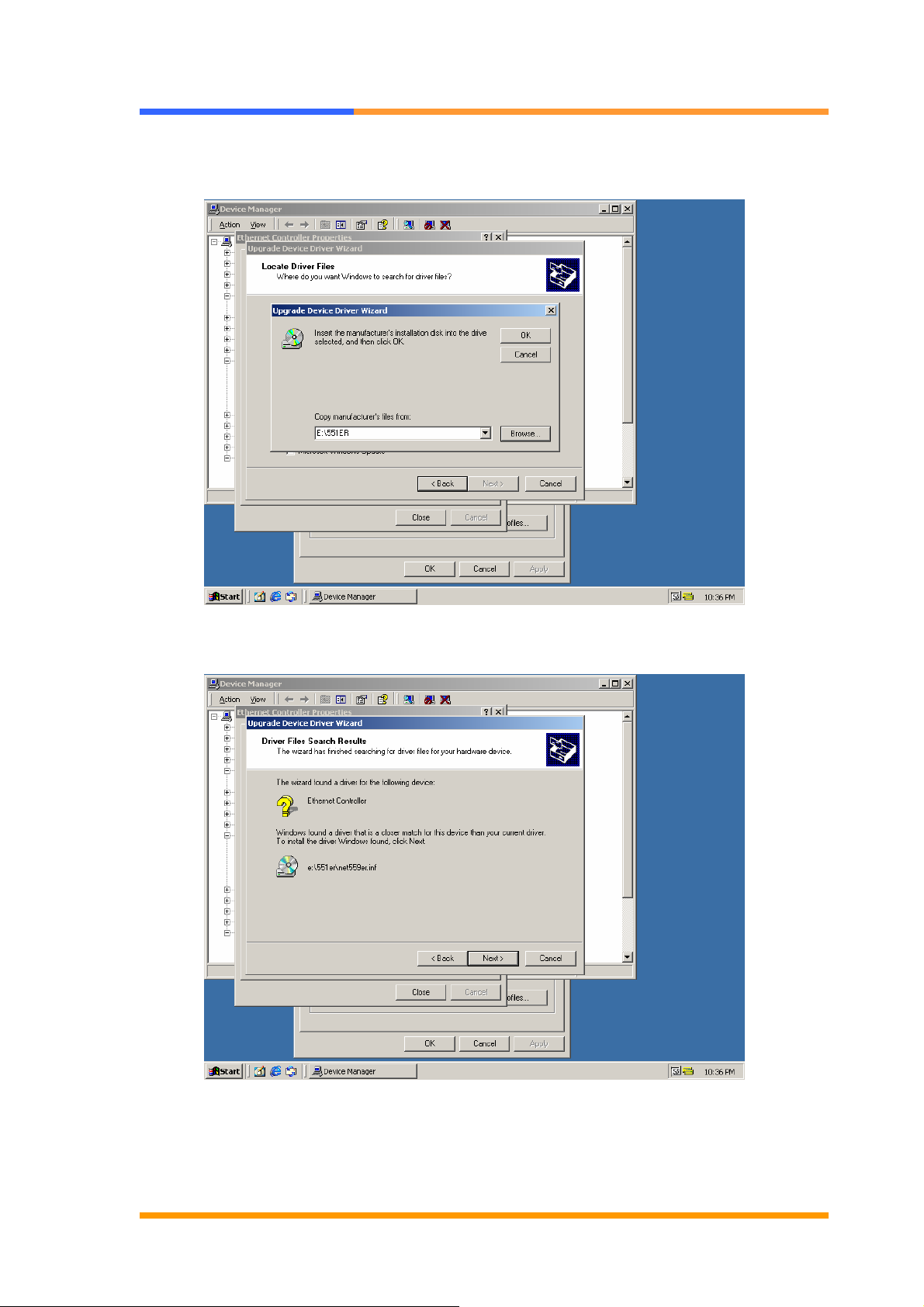
14. Find the Intel® 82551 or Reatek® 8139CL+ driver in the Setup CD.
15. Press the [OK] button.
16. Click the [Next] button.
©2006 AEWIN Technologies Co., Ltd. All rights reserved. Ver 1.1. Aug, 2006
40
Page 41
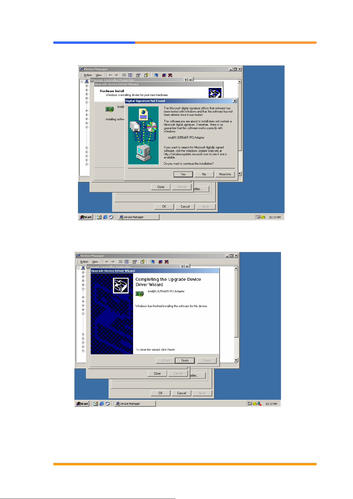
17. Click [Yes] button.
User’s Manual
18. Click [Finish] button then complete the installation.
©2006 AEWIN Technologies Co., Ltd. All rights reserved. Ver 1.1. Aug, 2006
41
Page 42
User’s Manual
4.4 RAID Driver Installation
CB-6970 supports RAID function in some models. Please check and install the driver
follow the below procedures.
1. Insert the setup CD of CB-6970 into your CD-ROM drive.
2. Choose the Drivers file to click the Setup icon.
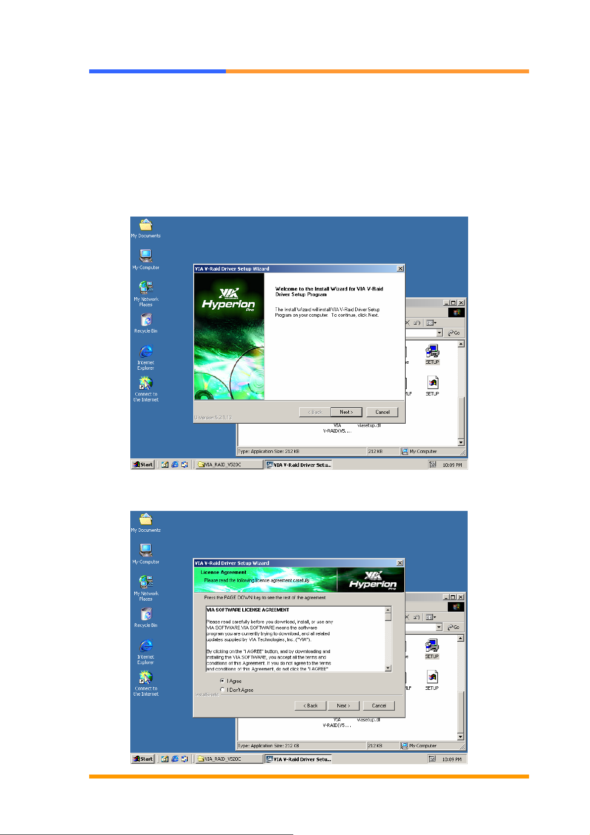
3. Click [Next] button.
4. Select <I Agree>. Click [Next] button.
©2006 AEWIN Technologies Co., Ltd. All rights reserved. Ver 1.1. Aug, 2006
42
Page 43
User’s Manual
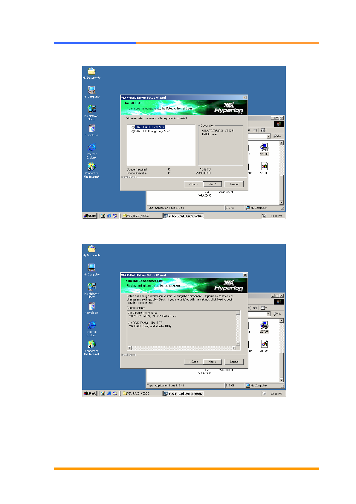
5. Choose the components you want to install, then click the [Next] button.
6. Click the [Next] button.
©2006 AEWIN Technologies Co., Ltd. All rights reserved. Ver 1.1. Aug, 2006
43
Page 44
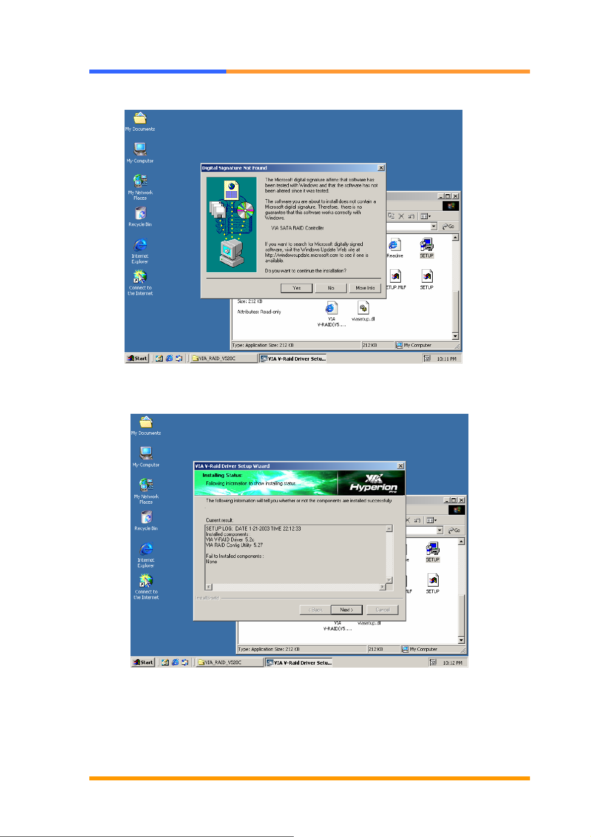
7. Click the [Yes] button.
User’s Manual
8. Click the [Next] button
©2006 AEWIN Technologies Co., Ltd. All rights reserved. Ver 1.1. Aug, 2006
44
Page 45
User’s Manual
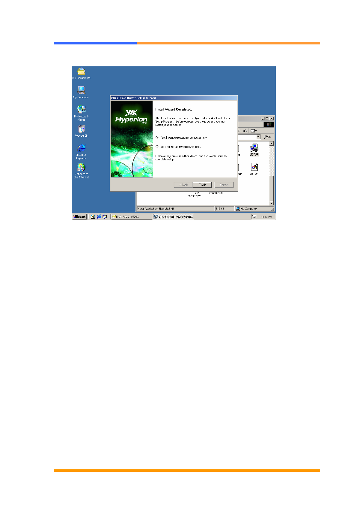
9. Click the [Finish] button to complete the installation.
©2006 AEWIN Technologies Co., Ltd. All rights reserved. Ver 1.1. Aug, 2006
45
Page 46
User’s Manual
4.5 VGA Driver Installation
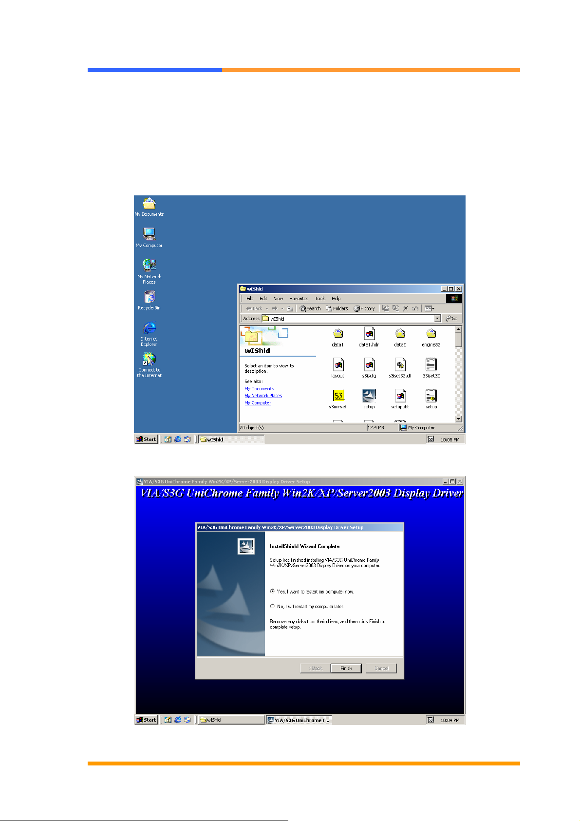
CB-6970 supports VGA display controlled by VIA/S3G Unichrome chipset. Please install
the driver follow the below procedures.
1. Insert the setup CD of CB-6970 into your CD-ROM drive.
2. Choose the Drivers file to click the Setup icon.
3. Follow the onscreen instruction to finish the driver installation in sequence.
©2006 AEWIN Technologies Co., Ltd. All rights reserved. Ver 1.1. Aug, 2006
46
Page 47

User’s Manual
Appendix A: Programming the Watchdog Timer
The CB-6970 provides a watchdog timer that resets the CPU or generates an interrupt if
processing comes to a stop. This function ensures greater system reliability in industrial
stand-alone and unmanned environments.
In order to enable the watchdog timer, you have to output the value of the watchdog timer
interval to the controller. The value range is from 01H to FFH, and the related time
watchdog timer interval is 1 sec to 255 sec.
Data Timer interval
00 Disabled
01 1 sec
02 2 sec
* *
* *
FF 255 sec
If you want to disable the watchdog timer, just set the timer interval value to 00H.
After setting the timer interval value, the watchdog timer begins to count down. You have to
refresh the watchdog timer, so that the watchdog timer will return to its initial value;
otherwise, your system will reset after a time-out. The following program shows how to set
the watchdog timer:
ASSEMBLY LANGUAGE DOS DEBUG
Program 1: Initializing the watchdog controller
MOV DX,2EH
MOV AL,87H
OUT DX,AL
OUT DX,AL
MOV AL,07H
O 2E 87
O 2E 87
O 2E 07
OUT DX,AL
MOV DX,2FH
MOV AL,08H
OUT DX,AL
Program 2: Writing a watchdog timer interval value
MOV DX,2EH
MOV AL,F6H
OUT DX,AL
©2006 AEWIN Technologies Co., Ltd. All rights reserved. Ver 1.1. Aug, 2006
47
O 2F 08
O 2E F6
O 2F XX
O 2E AA
Page 48

User’s Manual
MOV DX,2FH
MOV AL,XXH ; Timer interval *** see note ***
OUT DX,AL
MOV DX,2EH
MOV AL,AAH
OUT DX,AL
Note: This XX value range is from 01H to FFH, and the related watchdog
timer interval is 1 sec. to 255 sec. (as in the previous description).
Using the Demo Program
Update the System BIOS as follows:
1. Run Program 1
2. Run Program 2 (load the timer interval of 1EH, 30 seconds)
3. Run your Application Program #1 (Be sure your Application Program will finish
within 30 seconds)
4. Run Program 1
5. Run Program 2 (change the timer interval value to 3CH, 60 seconds)
6. Run your Application Program#2 (Be sure your Application Program will be finished
within 60 seconds)
7. Run Program 1
8. Run Program 2 (reload the timer interval value of 3CH, 60 seconds)
9. Run Program 1
Run Program 3 (Load the timer interval of 00H, and disable the watchdog timer
function)
©2006 AEWIN Technologies Co., Ltd. All rights reserved. Ver 1.1. Aug, 2006
48
Page 49

User’s Manual
Appendix B: Optional LAN Module
The CB-6970 can support additional two LAN ports via an optional Mini PCI LAN
module. With the LAN module equipped, CB-6970 can support six 10/100Mbps
LAN in total.
Part No. Description
R-050A Mini PCI module with two 10/100Mbps interface
R-051A Module with two RJ45 connectors
Appendix C: Optional Cable List
The CB-6970 is equipped with some cables for testing, verification, etc.
Part No. Item Connector Description
46-ATA660-00 IDE Cable IDE 1 2.54mm, 46cm, ATA-66/100
46-I001X4-00 IDE Power Cable CN15 2.54mm, 3cm, 4 pin power cable
46-IUSB01-00 USB Cable CN11 25cm
46-ICOM04-00 COM Port Cable CN10 22cm, D-Sub 9, 2*5
46-IPS200-00 KB/MS Cable CN13 15cm
46-IVGA01-00 VGA Cable CN12 2.00mm, D-Sub VGA Cable
©2006 AEWIN Technologies Co., Ltd. All rights reserved. Ver 1.1. Aug, 2006
49
 Loading...