

Page 1

AEWIN Technology Inc.
SOM-ETX
Model Number AW-BS710
Intel® Pentium® M / ULV Celeron M Processor with CRT/LVDS, LAN &
Audio
User’s Manual
Version 1.0
We embed your need! ©Copyright 2005
Page 2

User’s Manual
© Copyright 2005. All Rights Reserved
Manual Edition 1.0, Aug 2005
This document contains proprietary information protected by copyright. All rights
are reserved; no part of this manual may be reproduced, copied, translated or
transmitted in any form or by any means without prior written permission of the
manufacturer.
The content of this manual is intended to be accurate and reliable; the original
manufacturer assumes no responsibility for any inaccuracies that may be contained
in this manual. The original manufacturer reserves the right to make improvements
to the products described in this manual at any time without prior notice.
Trademarks
IBM, EGA, VGA, XT/AT, OS/2 and PS/2 are registered trademarks of International
business Machine Corporation
Award is a trademark of Award Software International, Inc
Intel is a trademark of Intel
RTL is a trademark of Realtek
VIA is a trademark of VIA Technologies, Inc
Microsoft, Windows, Windows NT and MS-DOS are either trademarks or registered
trademarks of Microsoft Corporation
All other product names mentioned herein are used for identification purpose only
and may be trademarks and/or registered trademarks of their respective companies
Limitation of Liability
While reasonable efforts have been made to ensure the accuracy of this manual, the
manufacturer and distributor assume no liability resulting from errors or omissions in
this manual, or from the use of the information contained herein.
©2005 AEWIN Technologies Co., Ltd. All rights reserved. 2 Ver 1.0. Aug, 2005
Page 3

User’s Manual
Table of Contents
Chapter 1. General Information...................................................................................... 4
1.1 Introduction............................................................................................................. 4
1.2 Specification............................................................................................................. 4
1.3 Package .................................................................................................................... 5
1.4 Precautions .............................................................................................................. 5
1.5 Board Layout........................................................................................................... 7
1.6 Board Dimension..................................................................................................... 8
Chapter 2. Memory Installation......................................................................................9
2.1 Install memory ........................................................................................................ 9
2.2 Remove Memory................................................................................................... 10
Chapter 3. BIOS Setup.....................................................................................................11
3.1 Quick Setup ............................................................................................................11
3.2 Entering the CMOS Setup Program...................................................................12
3.3 Menu Options........................................................................................................13
3.4 Standard CMOS Features Setup......................................................................... 14
3.5 Advanced BIOS Features Setup........................................................................... 15
3.6 Advanced Chipset Features Setup....................................................................... 17
3.7 Integrated Peripherals.......................................................................................... 19
3.8 Power Management Setup.................................................................................... 21
3.9 PNP/PCI Configuration........................................................................................ 24
3.10 PC Health Status Configuration Setup.............................................................26
3.11 Load Fail-Safe Defaults...................................................................................... 26
3.12 Load Optimized Defaults ................................................................................... 27
3.13 Supervisor/User Password ................................................................................. 27
3.14 Save and Exit Setup............................................................................................ 27
3.15 Exit Without Saving............................................................................................ 27
Chapter 4. Driver & Utility.............................................................................................. 28
4.1 Chipset Software Installation Utility................................................................... 28
4.2 CRT/LVDS Driver Installation............................................................................29
4.3 Ethernet Driver Installation................................................................................. 30
4.4 AC97 Audio Driver Installation........................................................................... 33
4.5 USB2.0 Driver Installation................................................................................... 34
©2005 AEWIN Technologies Co., Ltd. All rights reserved. 3 Ver 1.0. Aug, 2005
Page 4

User’s Manual
Chapter 1. General Information
1.1 Introduction
The AW-BS710 is a system-on-module based on ETX form factor. It can support
Pentium® M / ULV Celeron M processor. The chipsets equipped with AW-BS710 is
Intel® architecture of 852GM/855GME+ICH4. It can support DDR SO-DIMM socket
up to 1GB. Other features AW-BS710 has including Intel® 82551ER chipset
supporting one Ethernet port and CRT, LVDS panel interface, etc.
1.2 Specification
General Functions
CPU
BIOS
Cache
Chipset
I/O Chipset
Memory
Enhanced IDE
Serial port
KB/Mouse
Parallel port
USB
IR interface
Watchdog timer
Intel® Pentium® M / ULV Celeron® M processor
Award® 512KB Flash BIOS
512KB L2 cache
Intel® 852GM/855GME + ICH4
Winbond® 83627HF-AW
Onboard one DDR SO-DIMM socket can support up to 1GB
Support two IDE devices via Ultra DMA33/66/100 mode
Two RS232 (TTL, 16550 compatible) ports
Support PS/2 keyboard and mouse
Support bi-directional parallel port via SPP, ECP and EPP mode
Support four USB2.0/1.1 ports
Support SIR IrDA 1.0 compliant
Can generate a system reset, support software selectable timeout
interval
System Monitoring
Expansion
interface
Flat Panel/CRT Interface
Chipset
Display type
Display Memory
©2005 AEWIN Technologies Co., Ltd. All rights reserved. 4 Ver 1.0. Aug, 2005
Built in W83627HF-AW; support temperatures and voltage monitoring
Support ISA & PCI expansion interface
Built-in 852GM/855GME chipset
Support CRT and LVDS panel interface
Up to 32MB of dynamic video memory allocation
Page 5

Ethernet Interface
User’s Manual
Chipset
Audio Interface
Chipset
Mechanical and Environmental
Form Factor
Power supply voltage
Operating temperature
Board size
One Intel 82551ER 100Base-Tx Fast Ethernet controller
AC97 CODEC
ETX
VCC(4.75V to 5.25V)
32 to 140 ℉ (0 to 60℃)
4.5”(L) x 3.7”(W) (114mm x 94mm)
1.3 Package
Please make sure that the following items have been included in the
package before installation.
1. AW-BS710 SOM
2. Quick Installation Guide
3. CD-ROM that contains the following folders:
(1) Manual
(2) System Driver
(3) Ethernet Driver
(4) Utility Tools
If any item of above is missing or damaged, please contact your dealer
or retailer from whom you purchased the AW-BS710. Keep the box and
carton when you probably ship or store AW-BS710 in near future. After
you unpack the goods, inspect and make sure the packaging is intact.
Do not plug the power adapter to the main board of AW-BS710 if you
already find it appears damaged.
Note: Keep the AW-BS710 in the original packaging until you start installation.
1.4 Precautions
Please make sure you properly ground yourself before handling the AW-BS710
board or other system components. Electrostatic discharge can be easily damage
the AW-BS710 board.
Do not remove the anti-static packing until you are ready to install the AW-BS710
©2005 AEWIN Technologies Co., Ltd. All rights reserved. 5 Ver 1.0. Aug, 2005
Page 6

User’s Manual
board.
Ground yourself before removing any system component from it protective
anti-static packaging. To ground yourself, grasp the expansion slot covers or other
unpainted parts of the computer chassis.
Handle the AW-BS710 board by its edges and avoid touching the components on it.
©2005 AEWIN Technologies Co., Ltd. All rights reserved. 6 Ver 1.0. Aug, 2005
Page 7
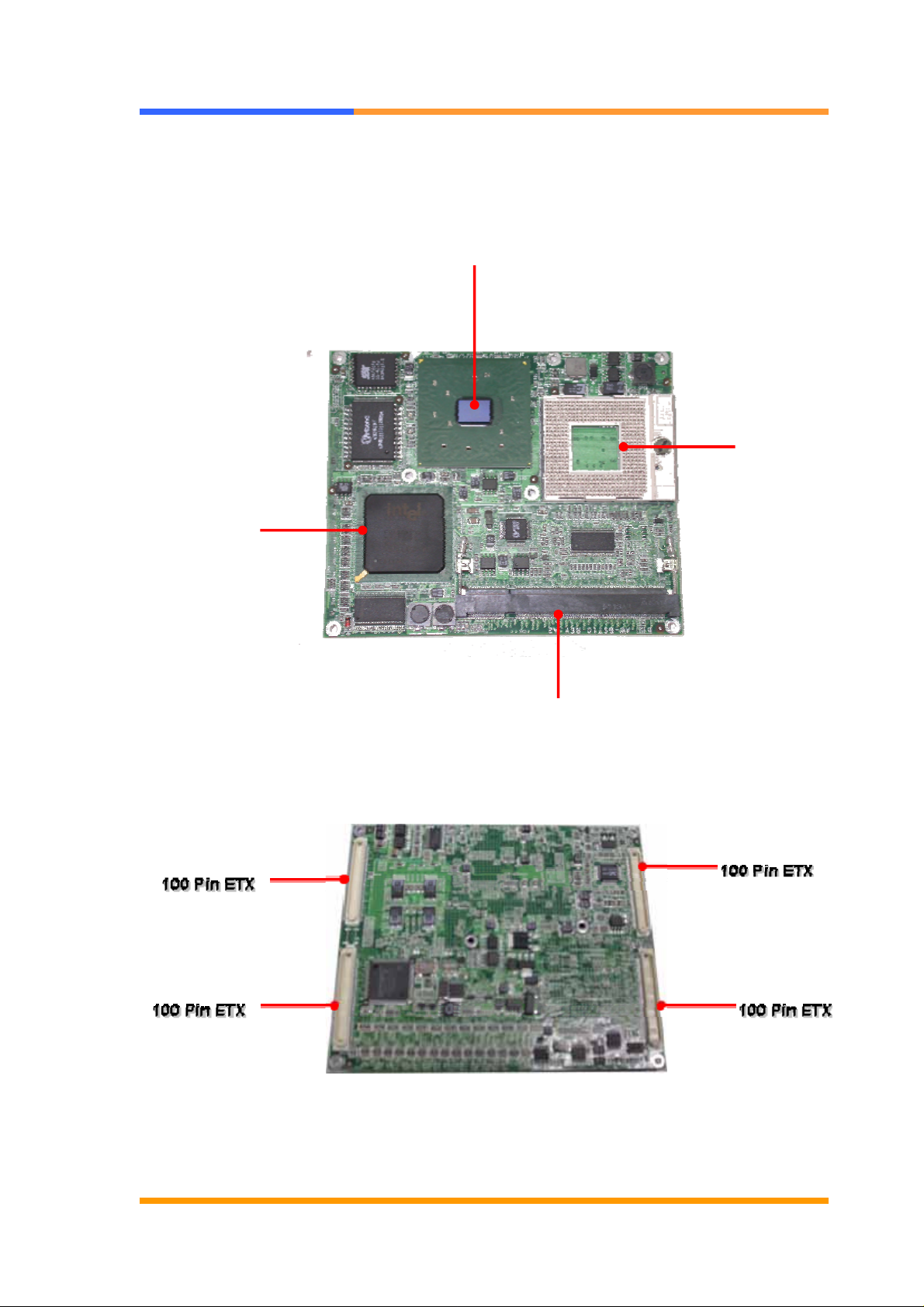
1.5 Board Layout
User’s Manual
(Front View)
Intel 852GM/855GME
Pentium M/Celeron
M CPU socket
Intel ICH4
SO-DIMM socket
(Rear View)
©2005 AEWIN Technologies Co., Ltd. All rights reserved. 7 Ver 1.0. Aug, 2005
Page 8
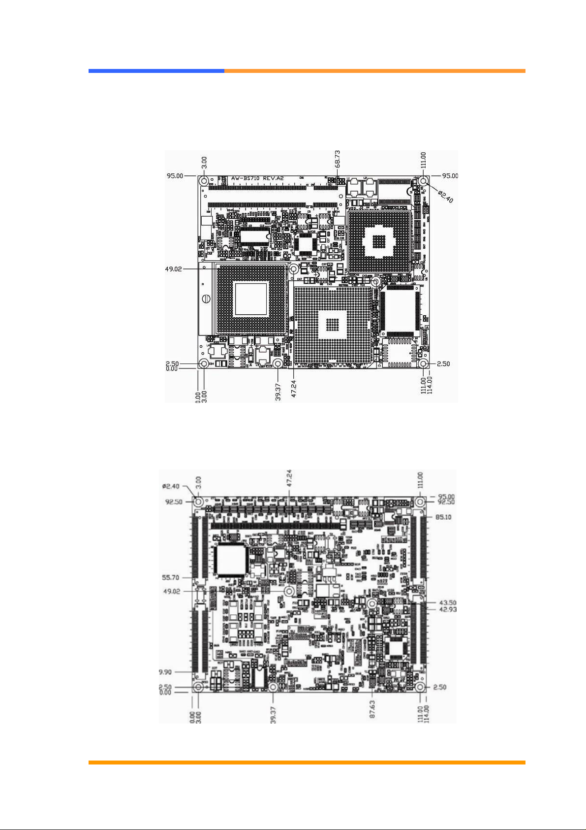
1.6 Board Dimension
User’s Manual
(Front View)
(Rear View)
©2005 AEWIN Technologies Co., Ltd. All rights reserved. 8 Ver 1.0. Aug, 2005
Page 9
User’s Manual
Chapter 2. Memory Installation
2.1 Install memory
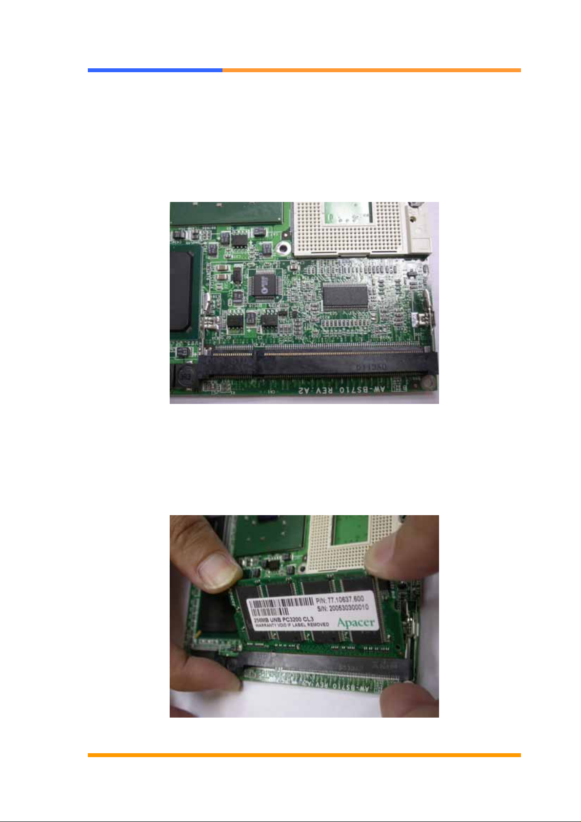
The AW-BS710 supports one SO-DIMM DDR socket, memory up to 1GB. Please
make sure to insert DDR with registered.
To Insert a DIMM Memory: Please align the module with the socket key and press
down until the levers at each end of the socket snap close up.
There is only one direction for installing a module in the socket. Do not attempt to
force the module into the socket incorrectly.
©2005 AEWIN Technologies Co., Ltd. All rights reserved. 9 Ver 1.0. Aug, 2005
Page 10
2.2 Remove Memory
User’s Manual
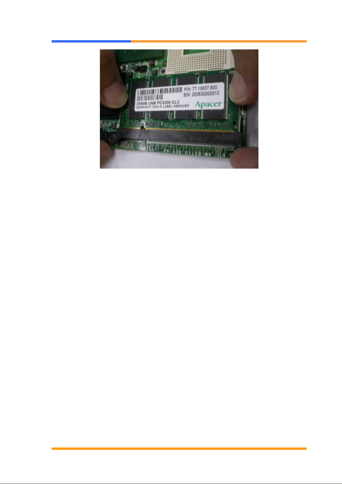
To Remove a DIMM Memory: To remove a DIMM, press down on the levers at both
end of the module until the module pops out
©2005 AEWIN Technologies Co., Ltd. All rights reserved. 10 Ver 1.0. Aug, 2005
Page 11

User’s Manual
Chapter 3. BIOS Setup
The ROM chip of your AW-BS710 board is configured with a customized Basic
Input/Output System (BIOS) from Phoenix-Award BIOS. The BIOS is a set of
permanently recorded program routines that give the system its fundamental
operational characteristics. It also tests the computer and determines how the
computer reacts to instructions that are part of programs.
The BIOS is made up of code and programs that provide the device-level control for
the major I/O devices in the system. It contains a set of routines (called POST, for
Power-On Self Test) that check out the system when you turn it on. The BIOS also
includes CMOS Setup program, so no disk-based setup program is required CMOS
RAM stores information for:
z Date and time
z Memory capacity of the main board
z Type of display adapter installed
z Number and type of disk drives
The CMOS memory is maintained by battery installed on the AW-BS710 board. By
using the battery, all memory in CMOS can be retained when the system power
switch is turned off. The system BIOS also supports easy way to reload the CMOS
data when you replace the battery of the battery power lose.
3.1 Quick Setup
In most cases, you can quickly configure the system by choosing the following main
menu options:
1. Choose “Load Optimized Defaults” from the main menu. This loads the setup
default values from the BIOS Features Setup and Chipset Features Setup
screens.
2. Choose “Standard COS Features” from the main menu. This option lets you
configure the date and time, hard disk type, floppy disk drive type, primary display
and more.
3. In the main menu, press F10 (“Save & Exit Setup”) to save your changes and
reboot the system.
©2005 AEWIN Technologies Co., Ltd. All rights reserved. 11 Ver 1.0. Aug, 2005
Page 12

User’s Manual
3.2 Entering the CMOS Setup Program
Use the CMOS Setup program to modify the system parameters to reflect the options
installed in your system and to customize your system. For example, you should
run the Setup program after you:
z Received an error code at startup
z Install another disk drive
z Use your system after not having used it for a long time
z Find the original setup missing
z Replace the battery
z Change to a different type of CPU
z Run the Phoenix-Award Flash program to update the system BIOS
Run the CMOS Setup program after you turn on the system. On-screen
instructions explain how to use the program.
Enter the CMOS Setup program’s main menu as follows:
1. Turn on or reboot the system. After the BIOS performs a series of
diagnostic checks, the following message appears:
“Press DEL to enter SETUP”
2. Press the <DEL> key to enter CMOS Setup program. The main menu
appears:
©2005 AEWIN Technologies Co., Ltd. All rights reserved. 12 Ver 1.0. Aug, 2005
Page 13

User’s Manual
3. Choose a setup option with the arrow keys and press <Enter>. See the
following sections for a brief description of each setup option.
In the main menu, press F10 (“Save & Exit Setup) to save your changes and
reboot the system. Choosing “EXIT WITHOUT SAVING” ignores your changes
and exits the program. Pressing <ESC> anywhere in the program returns you
to the main menu.
3.3 Menu Options
The main menu options of the CMOS Setup program are described in the following
and the following sections of this chapter.
STANDARD CMOS FEATURES:
Configure the date & time, hard disk drive type, floppy disk drive type, primary display
type and more
ADVANCED BIOS FEATURES:
Configure advanced system options such as enabling/disabling cache memory and
shadow RAM
ADVANCED CHIPSET FEATURES:
Configure advanced chipset register options such DRAM timing
INTEGRATED PERIPHERALS:
Configure onboard I/O functions
POWER MANAGEMENT SETUP:
Configure power management features such as timer selects
PNP/PCI CONFIGURATION:
Configure Plug & Play IRQ assignments and PCI slots
PC HEALTH STATUS:
Configure the CPU speed and, if the optional Winbond W83627HF system monitor
IC is installed, view system information
LOAD FAIL-SAFE DEFAULT:
Loads BIOS default values. Use this option as diagnostic aid if your system
behaves erratically
©2005 AEWIN Technologies Co., Ltd. All rights reserved. 13 Ver 1.0. Aug, 2005
Page 14
User’s Manual
LOAD OPTIMIZED DEFAULTS:
Loads optimized BIOS settings
SET SUPERVISORS & USER PASSWORD:
Configure the system so that a password is required when the system boots or you
attempt to enter the CMOS setup program. When you log in with this password, you
will be able to enter the COS Setup main menu, but you can not enter other menus in
the CMOS Setup program.
SAVE & EXIT SETUP:
Save changes of values to CMOS and exit the CMOS setup program
EXIT WITHOUT SAVING:
Abandon all CMOS changes and exit the CMOS setup program
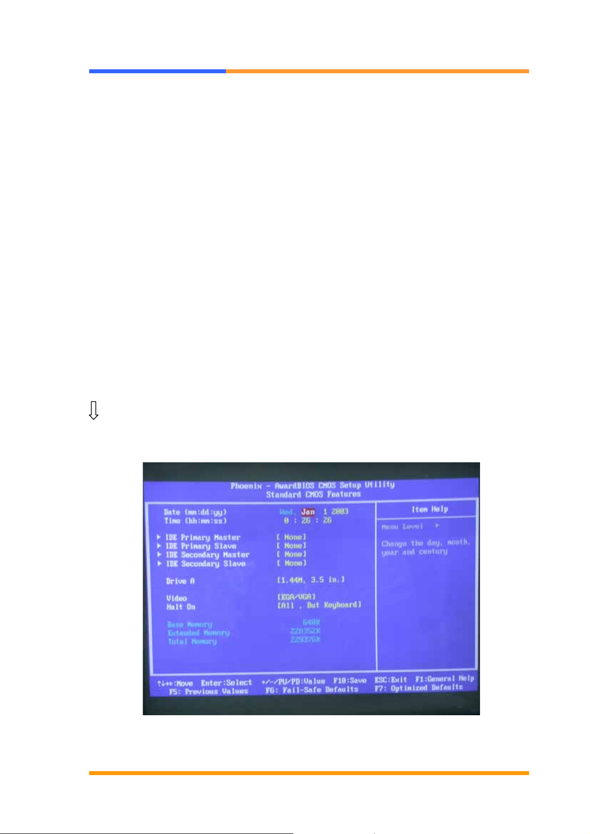
3.4 Standard CMOS Features Setup
Use the Standard CMOS Setup option as follows:
1. Choose “Standard CMOS Features” from the main menu. The following screen
appears:
2. Use the arrow keys to move between fields. Modify the selected field using the
PgUP/PgDN/+/- keys. Some fields let you enter numeric values directly.
©2005 AEWIN Technologies Co., Ltd. All rights reserved. 14 Ver 1.0. Aug, 2005
Page 15

User’s Manual
Option Description
Date (mm:dd:yy) Type the current date
Time
(hour:min:sec)
Hard Disks Choose from “Auto”, “User”, or “None”
Video Choose: EGA/VGA
Halt On Controls whether the system stops in case of an error detected
Type the current time (24-hour clock)
If your drive is not one of the predefined types, choose “User”
and enter the following drive specifications:
Cylinders, heads, Wpcom, L-Zone, sectors, and mode
Consult the documentation received with the drive for the values
that will give you optimum performance.
CGA 40
CGA 80
Mono
during power up.
Choose: All Errors
No Errors
All, But Keyboard (Default)
All, But Diskette
All, But Disk/Key
3. After you have finished with the Standard CMOS Features program, press the
<ESC> key to return to the main menu.
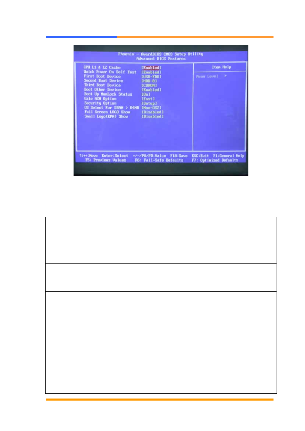
3.5 Advanced BIOS Features Setup
Use the Advanced BIOS Features Setup option as follows:
1. Choose “Advanced BIOS Features Setup” from the main menu. The following
screen appears:
©2005 AEWIN Technologies Co., Ltd. All rights reserved. 15 Ver 1.0. Aug, 2005
Page 16
User’s Manual
2. Use the arrow keys to move between items and to select values. Modify the
selected fields using the PgUP/PgDN keys. Press the <F1> “Help” key for
information on the available options:
Option Description
CPU L1 & L2 Cache This field is used to speed up the memory access.
Enable the external cache for better performance.
Quick Power On Self-Test: Will enable you to cancel some checking item and
increase the speed when you open the machine.
First/Second/Third Boot
Device
Boot Other Device Enable other device bootable not selected above.
Boot Up NumLock Status Choose On or Off. On puts the numeric keypad in
The BIOS attempts to load the operating system from
the devices in the sequence selected in these items.
Choose: HDD-0, LS-120, USB FDD…..
Num Lock mode at boot-up. Off puts the numeric
keypad in arrow key mode at boo-up.
Gate A20 Option This entry allows you to select how gate A20 is
handled. Gate A20 is a device use to address memory
above 1MB. Initially, gate A20 was handled via the
keyboard controller. Today, while keyboards still
provide this support, it is more common, and much
faster, for the system chipset to provide support for
gate A20.Fast. The chipset controls Gate A20.
©2005 AEWIN Technologies Co., Ltd. All rights reserved. 16 Ver 1.0. Aug, 2005
Page 17
User’s Manual
Normal A [o mom the keyboard controls Gate A20.
Security Option Choose Setup or System. This lets you specify
whether a password is required every time the system
boots or only when an attempt is made to enter the
CMOS Setup program.
“Setup” – The password prompt only appears if you
attempt to enter the CMOS setup program.
“System” – The password prompt appears each time
the system is booted.
Note: The password function is disabled by default.
For a description of enabling the password function,
refer to the section: Supervisor Password & User
Password later in this chapter.
OS Select for DRAM > 64MB Set to OS/2 if your system is using OS/2 and has a
memory size of more than 64MB
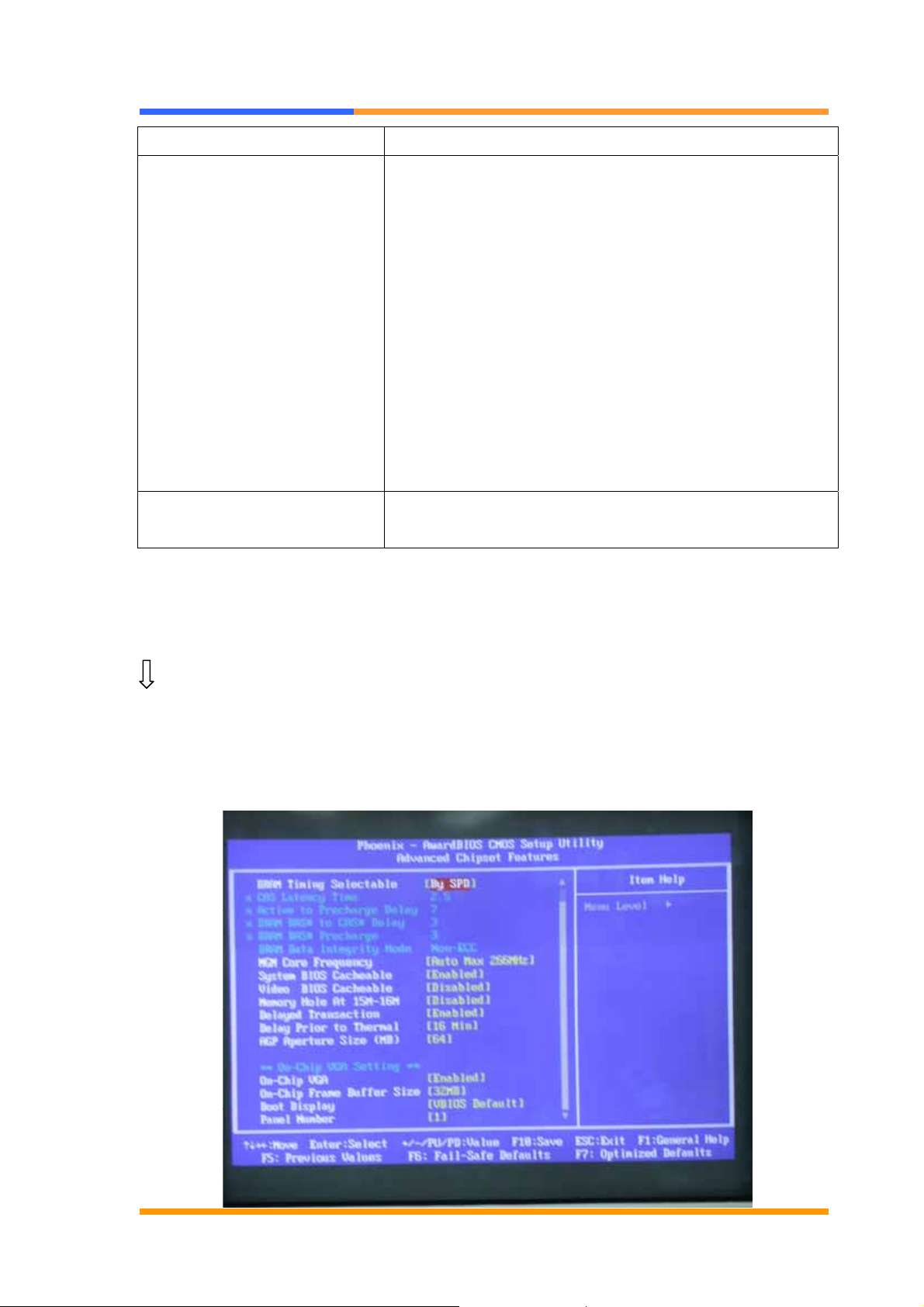
3.6 Advanced Chipset Features Setup
Use the Advanced Chipset Features Setup option as follows:
1. Choose “Advanced Chipset Features Setup” from the main menu. The following
screen appears;
©2005 AEWIN Technologies Co., Ltd. All rights reserved. 17 Ver 1.0. Aug, 2005
Page 18

User’s Manual
2. Move between items and select values by using the arrow keys. Modify the
selected fields using the PnUP/PgDN Keys. For information on the various options,
press
<F1> key .
Option Description
DRAM Timing Control This field is used to select the timing of the DRAM.
DRAM timing Configure < By SPD>
X – CAS Latency Time 2
X – Active to Precharge Delay 5
X- DRAM RAS # to CAS# Delay 2
X – DRAM RAS# Precharge 2
DRAM Data Integrity Mode Choose ECC or Non –ECC
CAS Latency Time This field is used to select the local memory clock
periods.
Active to Precharge Delay Provide parameter of SDRAM for reference.
DRAM RAS# to CAS# Delay Control the command order and start the cycle time
for read/write command by SDRAM
DRAM RAS# Precharge This field controls RAS# precharge (in local memory
clocks)
System BIOS Cacheable Choose Enabled or Disabled. When enabled,
caching of the system BIOS at F0000h-FFFFFh,
enhancing system performance. However, if any
program writes to this memory area, a system error
may result.
Video BIOS Cacheable Choose Enabled or Disabled. When Enable this
option to allow caching of the Video BIOS.
Memory Hole At 15M-16M Choose Enabled or Disabled. You can reserve this
area of system memory for ISA adapter ROM.
When this area is reserved, it can not be cached.
The user information of peripherals that need to use
this area of system memory usually discusses their
memory requirement.
AGP Aperture Size (MB) This field is relevant to the memory-mapped
graphics data of the AGP card installed in your
system. Leave this in its default setting.
©2005 AEWIN Technologies Co., Ltd. All rights reserved. 18 Ver 1.0. Aug, 2005
Page 19
User’s Manual
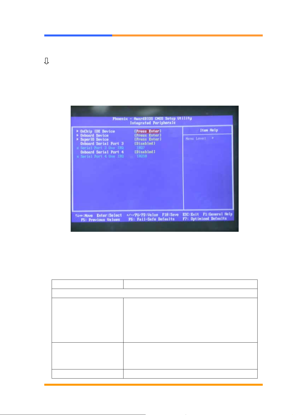
3.7 Integrated Peripherals
Use the Integrated Peripherals Setup option as follows:
1. Choose “Integrated Peripherals Setup” from the main menu. The following
screen appears:
2. Move between items and select values by using the arrow keys. Modify the
selected fields using the PgUP/PgDN keys. Please press the <F1> key for
information on the various options.
Option Description
Onboard Device
USB Controller Enabled the onboard USB. You can further
configure the onboard USB in the “USB 2.0
controller” and ‘USB Keyboard Support” fields.
Disables the onboard USB.
USB2.0 Controller If you are using USB2.0, this field must be set to
Enabled.
AC97 Audio Auto Select this option when using the
©2005 AEWIN Technologies Co., Ltd. All rights reserved. 19 Ver 1.0. Aug, 2005
Page 20

Super IO Device
User’s Manual
onboard audio codec.
Disabled Select this option when using a PCI
sound card.
Power ON Function
KB Power ON Password User define
Hot KEY Power ON User define
Onboard Serial Port 1
Onboard Serial Port 2
Onboard Parallel Port
Parallel Port Mode SPP/EPP/ECP/ECP+EPP
EPP Mode Select EPP1.7
ECP Mode Use DMA 3
Power After PWR-Fail Off/On/Former-S ts
POWER ON Function
The power button will not function once a keyboard password has been set in this
Password、Hot Key、Any Key、Button
Only、Keyboard 98
3F8/IRQ4、2F8/IRQ3、3E8/IRQ4、
2E8/IRQ3、AUTO
3F8/IRQ4、2F8/IRQ3、3E8/IRQ4、
2E8/IRQ3、AUTO
37//IRQ7、278/IRQ5、3BC/IRQ7
field. You must type the correct password to power-on the system. If you forgot the
password, turn off the system and remove the battery. Wait for a few seconds and
install it back before powering-on the system.
IR Mode Select
This field is used to select the type of IrDA standard supported by your IrDA device.
For better transmission of data, your IrDA peripheral device must be within a 30°
angle and within a distance of 1 meter.
RxD, TxD Active
The options are Hi, Lo; Lo, Hi; Lo, Lo; and Hi, Hi.
UR2 Duplex Mode
Half Data is completely transmitted before receiving data.
Full Transmits and receives data simultaneously.
Onboard Parallel Port
378/IRQ7, 3BC/IRQ7, 278/IRQ5 Selects the I/O address and IRQ for the onboard
©2005 AEWIN Technologies Co., Ltd. All rights reserved. 20 Ver 1.0. Aug, 2005
Page 21

User’s Manual
parallel port.
Disabled Disables the onboard parallel port.
Parallel Port Mode
The options are SPP, EPP, ECP and ECP+EPP. These apply to a standard
specification and will depend on the type and speed of your device. Refer to your
peripheral’s manual for the best option.
SPP
Allows normal speed operation but in one direction only.
ECP (Extended Capabilities Port)
Allow parallel port to operate in bidirectional modes and at a speed faster than the
normal mode’s data transfer rate.
EPP (Enhanced Parallel Port)
Allows bidirectional parallel ports to operation at maximum speed.
If you selected EPP, the “ EPP Mode Select” field is configurable. If you selected ECP,
the “ECP Mode Use DMA: field is configurable. If you selected ECP+EPP, both “ EPP
Mode Select: and “ECP Mode Use DMA” are configurable.
PWRON after PWR-Fail
This function allows you to setup the system whether you want restart or shut down
the machine after the powers interrupt.
Off: Remain system closed when you restart the power
On: when restart the power it will remain the status that power is not interrupt.
Former-Sts: The system will back to the status that power is not interrupt.
Watch Dog Timer Select
You can set up the watchdog timer.
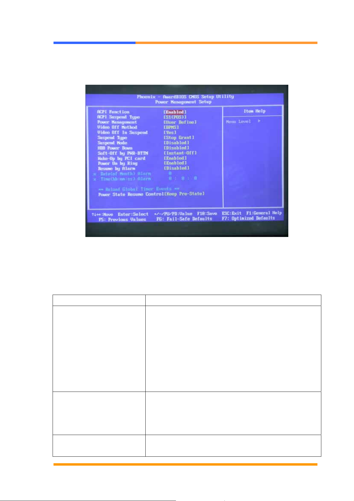
3.8 Power Management Setup
The Power Management Setup controls the board’s “green” features. To save
energy these features shut down the video display and hard disk drive.
Use the Power Management Setup option as follows:
©2005 AEWIN Technologies Co., Ltd. All rights reserved. 21 Ver 1.0. Aug, 2005
Page 22
User’s Manual
1. Choose “Power Management Setup” from the main menu. The following screen
appears.
2. Move between items and select values by using the arrow keys. Modify the
selected field the PgUP/PgDN keys. For information on the various options,
press <F1> key.
Option Description
ACPI Function This function should be enabled only in operating
systems that support ACPI. Currently, only Windows
98SE/2000/ME/XP supports this function. When this
field is enabled, the system will ignore the settings in
the “Suspend Mode” and “HDD Power Down” fields. If
you want to use the Suspend to RAM function, make
sure this field is enabled then select “S3 (STR” in the
field below.
ACPI Suspend Ty pe This field is used to select the type of Suspend mode.
S1 (POS) Enables the Power On Suspend function.
S3 (STR) Enables the Suspend to RAM function. You
can further configure this function by setting.
The “Run VGABIOS if S3
Resume” and “USB KB
©2005 AEWIN Technologies Co., Ltd. All rights reserved. 22 Ver 1.0. Aug, 2005
When this field is set to Auto, the system will initialize
the VGA BIOS when it wakes up from the S3 state. This
Page 23

Wake-up From S3” fields.
User’s Manual
can be configured only if the “ACPI Suspend Type”field
Run VGABIOS if S3
Resume
Power Management This field allows you to select the type (or degree) of
Video Off Method This determines the manner in which the monitor is
is set to “ S3 (STR)”
power saving by changing the length of idle time that
elapses before the “Suspend Mode” and “HDD Power
Down” field is activated. Min Saving Minimum power
saving time for the “ Suspend Mode” and “HDD Power
Down” =15min.
Max Saving Maximum power saving time for the
“Suspend Mode” and “HDD Power Down”=1 min.
User Define Allows you to set the power saving time in
the “Suspend Mode” and “HDD Power Down” field.
blanked. V/H SYNC + Blank This selection will cause
the system to turn off the vertical and horizontal
synchronization ports and write blanks to the video
buffer.
Bland Screen This option only writes blanks to the video buffer.
DPMS initializes display power management signaling.
Use this option if your video board supports it. Video
Off In Suspend This field is used to activate the video
off feature when the system enters the Suspend mode.
Suspend Mode When the system enters the Suspend mode, the CPU
and onboard peripherals will be shut off.
HDD Power Down This is selectable only when the power management
filed is set to user define. When the system enters the
HDD power down mode according to the power saving
time selected, the hard disk drive will be powered down
while all other devices remain active.
Soft-Off by PWR-BTTN This field allows you to select the method of powering
off you system.
Delay 4 sec. regardless of whether the power
management function is enable or disabled, if the
power button is pushed and released in less than 4
sec, the system enter the suspend mode. The purpose
of this function is to prevent the system from powering
off in case you accidentally “ hit” or pushed the power
©2005 AEWIN Technologies Co., Ltd. All rights reserved. 23 Ver 1.0. Aug, 2005
Page 24

User’s Manual
button. Push and release again in less than 4 sec to
restore. Pushing the power button for more than 4
seconds will power off the system.
Instant-off Pressing and then releasing the power button at once
will immediately power off your system.
Resume on PCI Event Enable this field should be set to enabled only if your
PCI card such as LAN card or modem card uses the
PCI PME (Power Management Event) signal to
remotely wake up the system. Access to the LAN card
or PCI card will cause the system to wake up. Refer to
the Disable The system will not wake up despite
access to the PCI card.
Wake up on LAN If you are using a LAN card that supports the remote
wake up function, set this field to Enabled. The will
allow the network to remotely wake up a soft power
down (Soft-off) PC. However, if your system is in the
suspend mode, you can wake up the system only
through an IRQ or DMA interrupt.
Resume By Alarm Enabled when enabled, you can set the date and time
you would like the soft power down (Soft-off) PC to
power –on in the “Date (of Month) Alarm” and “Time
(hh:mm:ss) Alarm” fields. However, if the system is
accessed by incoming calls or the network (Resume
On Ring/LAN) that prior to the date and time set in
these fields, the system will give priority to the incoming
calls or network.
Disabled Disables the automatic power-on function.
(Default)
3. After you have finished with the Power Management Setup, press the <ESC> key
to return to the main menu.
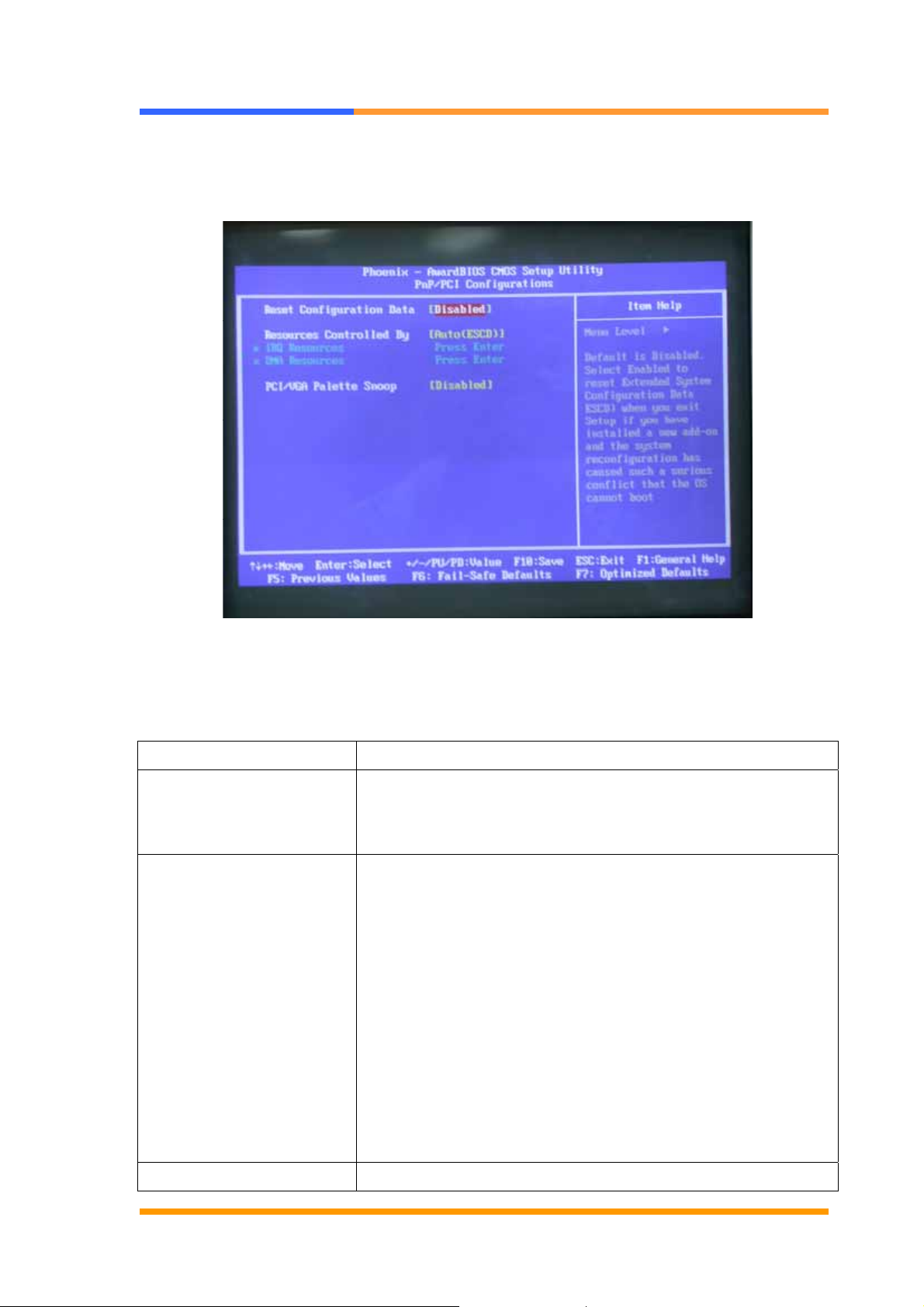
3.9 PNP/PCI Configuration
This option is used to configure Plug and Play assignments and route PCI interrupts
to designated ISA interrupts.
Use the PNP/PCI Configuration Setup option as follows:
©2005 AEWIN Technologies Co., Ltd. All rights reserved. 24 Ver 1.0. Aug, 2005
Page 25
User’s Manual
1. Choose “PNP/PCI Configuration Setup” from the main menu, the following screen
appears.
2. Move between items and select values by using the arrow keys. Modify the
selected fields using the PgUP/PgDN keys. For information on the various
options, please press <F1> key.
Option Description
PNP OS installed NO: BIOS program will adjust all the set up by itself
YES: When you install the system that support plug &
play, press <YES>
Reset Configuration Data Enabled The BIOS will reset the Extended System
Configuration Data (ESCD) once automatically. It will then
recreate a new set of configure data
Disabled The BIOS will not reset the configuration data
Resources controlled by the Award plug and play BIOS
has the capability to automatically configure all of the boot
and plug and play compatible devices.
Auto (ESCD) The system will automatically detect the
settings for you.
Manual choose the specific IRQ in the “ IRQ Resources”
field.
PCI/VGA Palette Snoop This field determines whether the MPEG ISA/VESA VGA
©2005 AEWIN Technologies Co., Ltd. All rights reserved. 25 Ver 1.0. Aug, 2005
Page 26
User’s Manual
cards a work with PCI/VGA or not
Enable MEPG ISA/VESA VGA cards work with PCI/VGA
Disabled MPEG ISA/VESA VGA card does not work with
PCI/VGA
3. Please press the <ESC> key to return the main menu after finishing with the
PNP/PCI Configuration Setup.
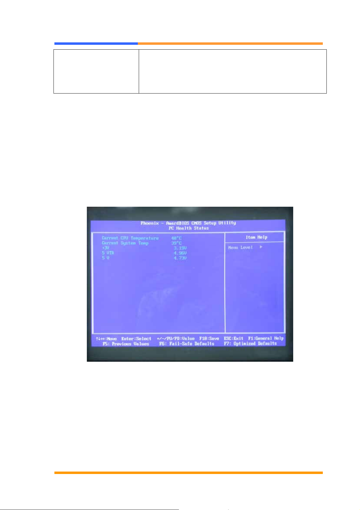
3.10 PC Health Status Configuration Setup
Choose “PC Health Status Configuration Setup” from the main menu, the following
screen appears:
3.11 Load Fail-Safe Defaults
This option loads the troubleshooting default values permanently stored in the BIOS
ROM. This is useful if you are having problems with the main board and need to
debug or troubleshoot the system. The loaded default settings do not affect the
Standard CMOS Setup screen.
To use this feature, highlight it on the main screen and press <Enter>. A line will
©2005 AEWIN Technologies Co., Ltd. All rights reserved. 26 Ver 1.0. Aug, 2005
Page 27

User’s Manual
appear on the screen asking if you want to load the BIOS default values. Pres the
<Y> key and then press <Enter> if you want to load the BIOS default.
3.12 Load Optimized Defaults
This option loads optimized settings stored in the BIOS ROM. The auto-configured
settings do not affect the Standard CMOS Setup screen.
To use this feature, highlight it on the main screen and press <Enter>. A line will
appear on the screen asking if you want to load the Optimized Default Values.
Press the <Y> key and then press <Enter> if you want to load the SETUP default.
3.13 Supervisor/User Password
The password options let you prevent unauthorized system boot-up or unauthorized
use of CMOS setup. The Supervisor Password allows both system and CMOS
Setup program access; the User Password allows access to the system and the
CMOS Setup Utility main menu.
The password functions are disabled by default. You can use these options to
enable a password function or, if a password function is already enabled, change the
password.
To change a password, first choose a password option from the main menu and enter
the current password. Then type your new password at the prompt. The password
is case sensitive and you can use up to 8 alphanumeric characters. Press <Enter>
after entering the password. At the Next Prompt, confirm the new password by
typing it and pressing <Enter> again.
After you use this option to enable a password function, use the “Security Option” in
“BIOS Feature Setup” to specify whether a password is required every time the
system boots or only when an attempt is made to enter the CMOS Setup program.
3.14 Save and Exit Setup
This function automatically saves all CMOS values before exiting Setup.
3.15 Exit Without Saving
Use this function to exit Setup without saving the CMOS value.
©2005 AEWIN Technologies Co., Ltd. All rights reserved. 27 Ver 1.0. Aug, 2005
Page 28
User’s Manual
Chapter 4. Driver & Utility
The system driver installation procedure must be performed first.
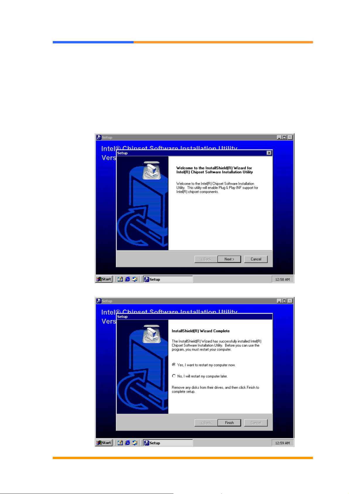
4.1 Chipset Software Installation Utility
It enables plug & play INF support for Intel® chipset components. Insert the setup
CD then install the driver following the instruction.
©2005 AEWIN Technologies Co., Ltd. All rights reserved. 28 Ver 1.0. Aug, 2005
Page 29
User’s Manual
4.2 CRT/LVDS Driver Installation
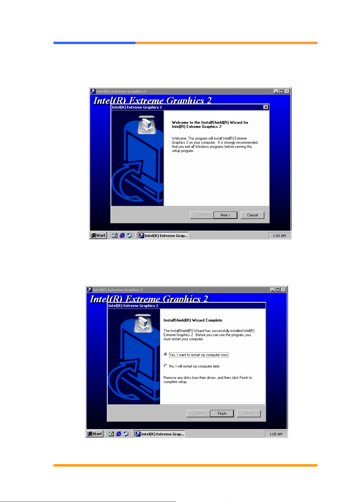
It support CRT or LVDS display function. Double click the utility in the setup CD to
finish the installation.
©2005 AEWIN Technologies Co., Ltd. All rights reserved. 29 Ver 1.0. Aug, 2005
Page 30
User’s Manual
4.3 Ethernet Driver Installation
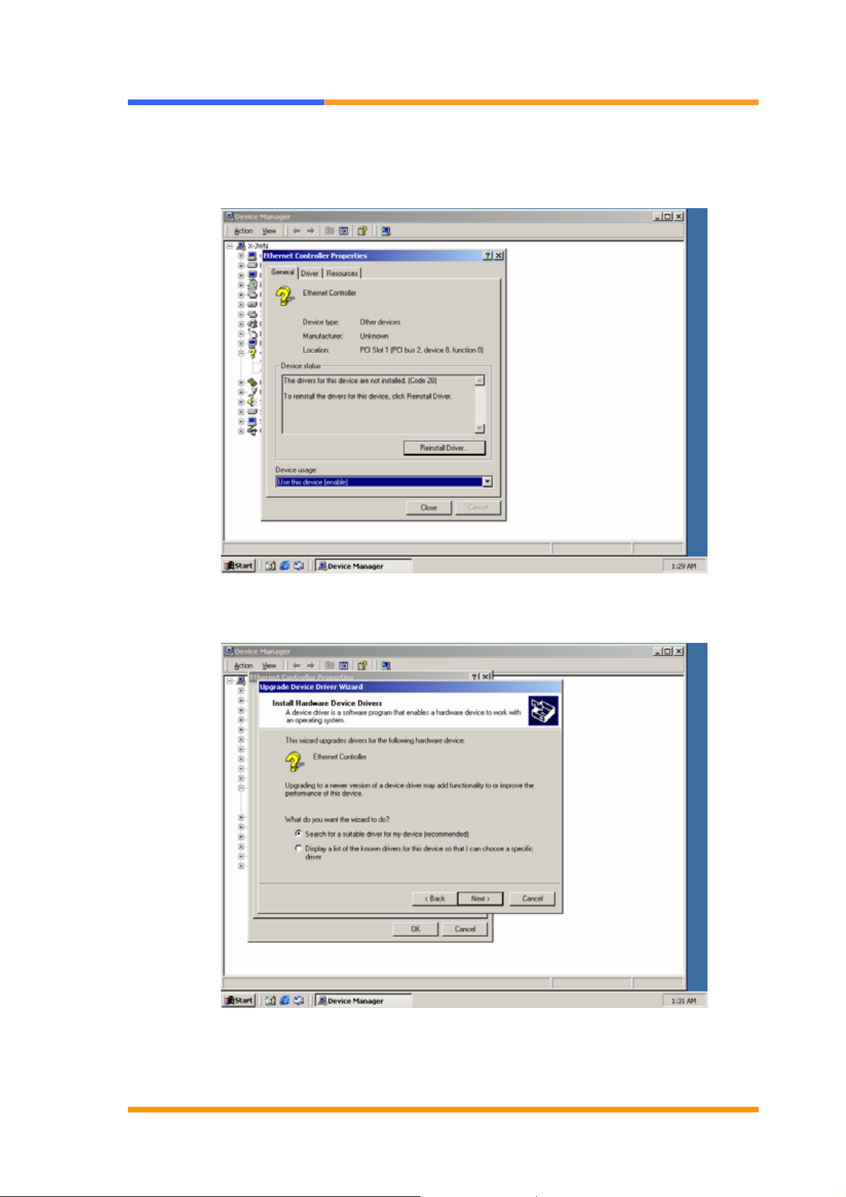
It supports the 10/100 Ethernet function by using Intel® 82551ER. Go to the
“Device Manager”, choose the “Ethernet Controller” to update the driver.
Choose the “Search for a suitable driver for my device”, click “Next” button.
©2005 AEWIN Technologies Co., Ltd. All rights reserved. 30 Ver 1.0. Aug, 2005
Page 31
User’s Manual
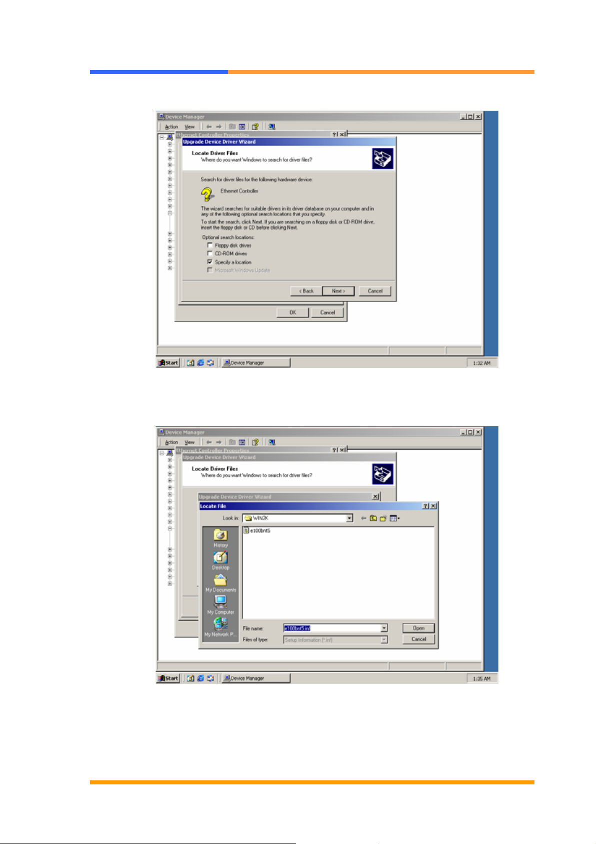
Choose “Specify a location”, then click “Next” button.
Find the driver file in the setup CD directory, choose the file then click “Open” button.
©2005 AEWIN Technologies Co., Ltd. All rights reserved. 31 Ver 1.0. Aug, 2005
Page 32
User’s Manual
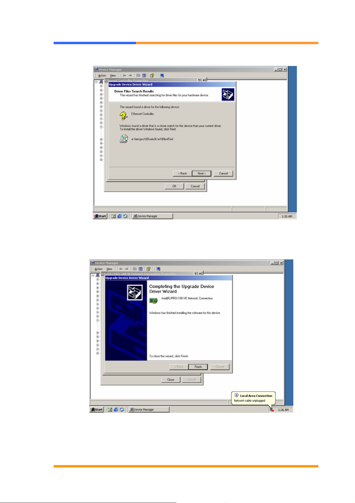
Find the correct driver file, then press the “Next” button.
Press “Finish” button to complete the installation.
©2005 AEWIN Technologies Co., Ltd. All rights reserved. 32 Ver 1.0. Aug, 2005
Page 33
User’s Manual
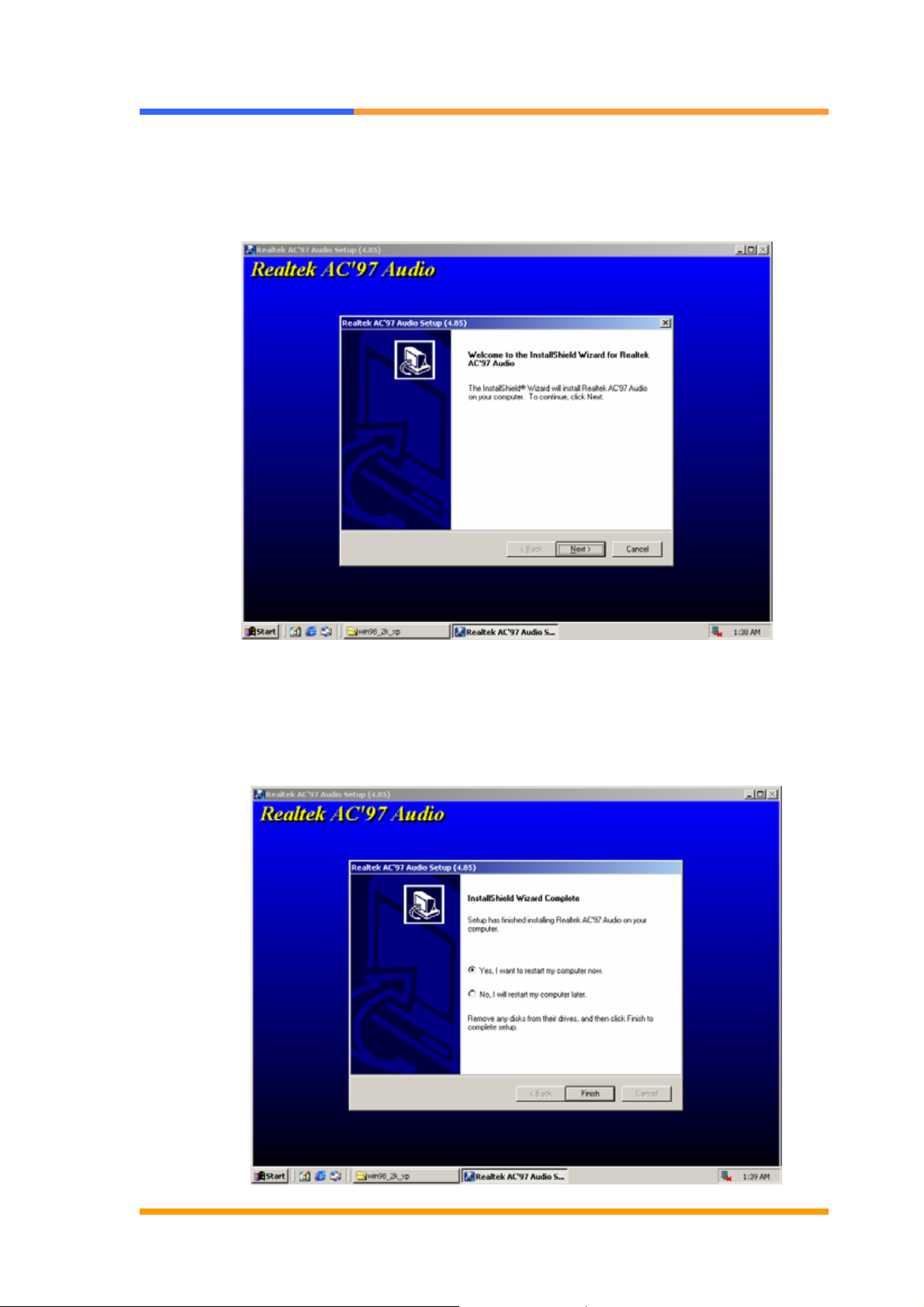
4.4 AC97 Audio Driver Installation
It supports AC97 audio function by using Realtek CODEC. Do uble click the file in
the setup CD, follow the instruction to finish the installation.
Choose “Yes, I want to restart my computer now”, then press “Finish” button to
complete the installation.
©2005 AEWIN Technologies Co., Ltd. All rights reserved. 33 Ver 1.0. Aug, 2005
Page 34
User’s Manual
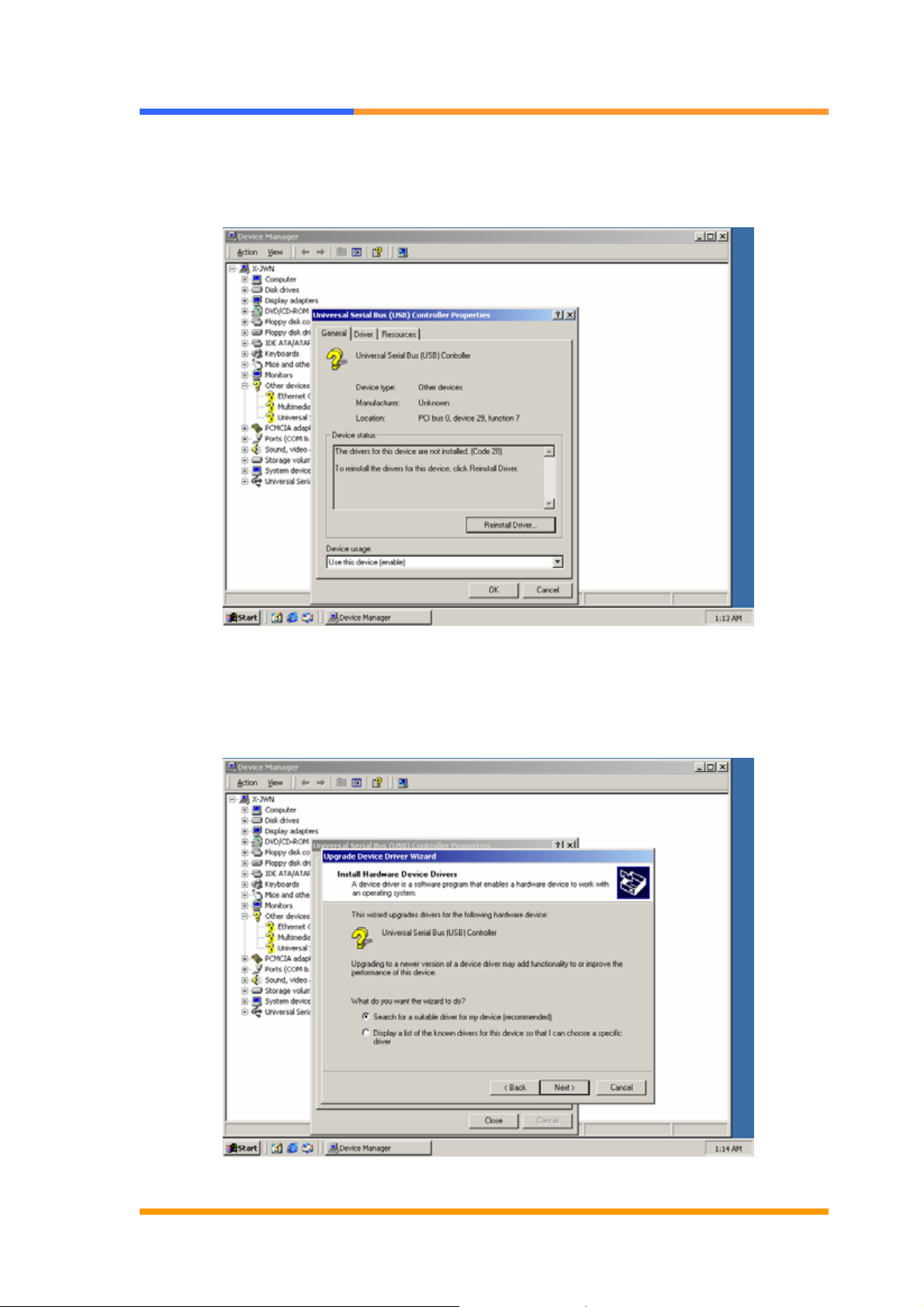
4.5 USB2.0 Driver Installation
Go to the “Device Manager”, choose “Universal serial bus” to update the driver.
Choose “Search a suitable driver for my device”, then press “Next” button.
©2005 AEWIN Technologies Co., Ltd. All rights reserved. 34 Ver 1.0. Aug, 2005
Page 35
User’s Manual
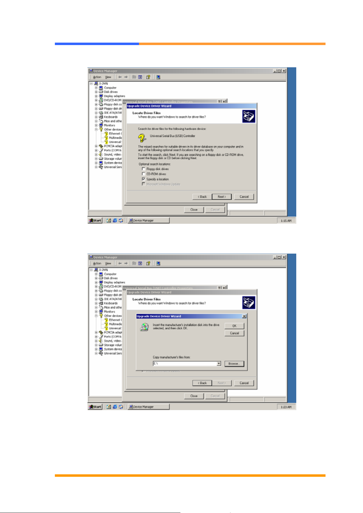
Choose “Specify a location”, then press “Next” button.
Choose the drive and file the setup CD is located, then press “Next” button.
©2005 AEWIN Technologies Co., Ltd. All rights reserved. 35 Ver 1.0. Aug, 2005
Page 36
User’s Manual
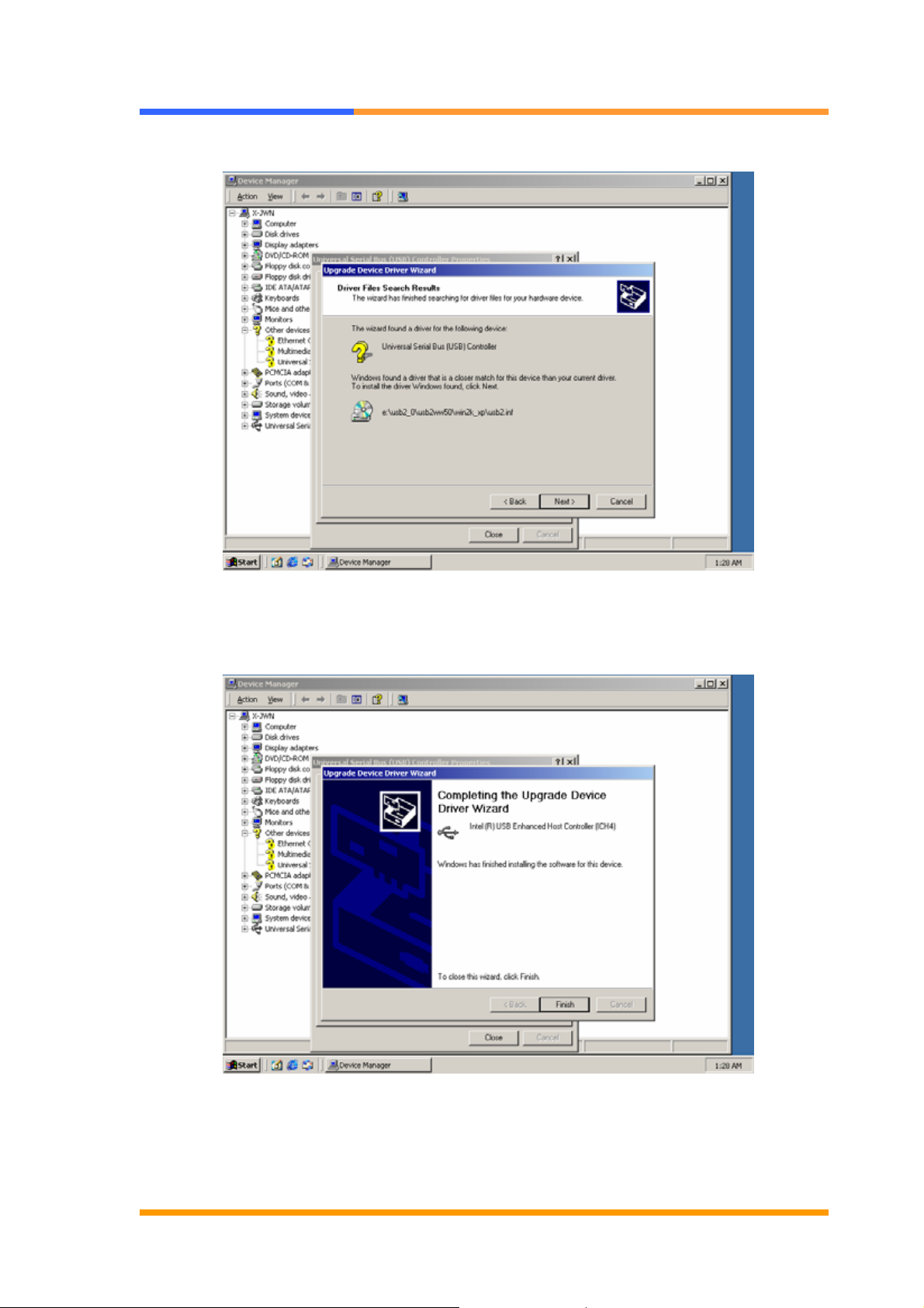
Find the correct driver, then press “Next” button.
Press “Finish” button to complete the installation.
©2005 AEWIN Technologies Co., Ltd. All rights reserved. 36 Ver 1.0. Aug, 2005
 Loading...