

Page 1
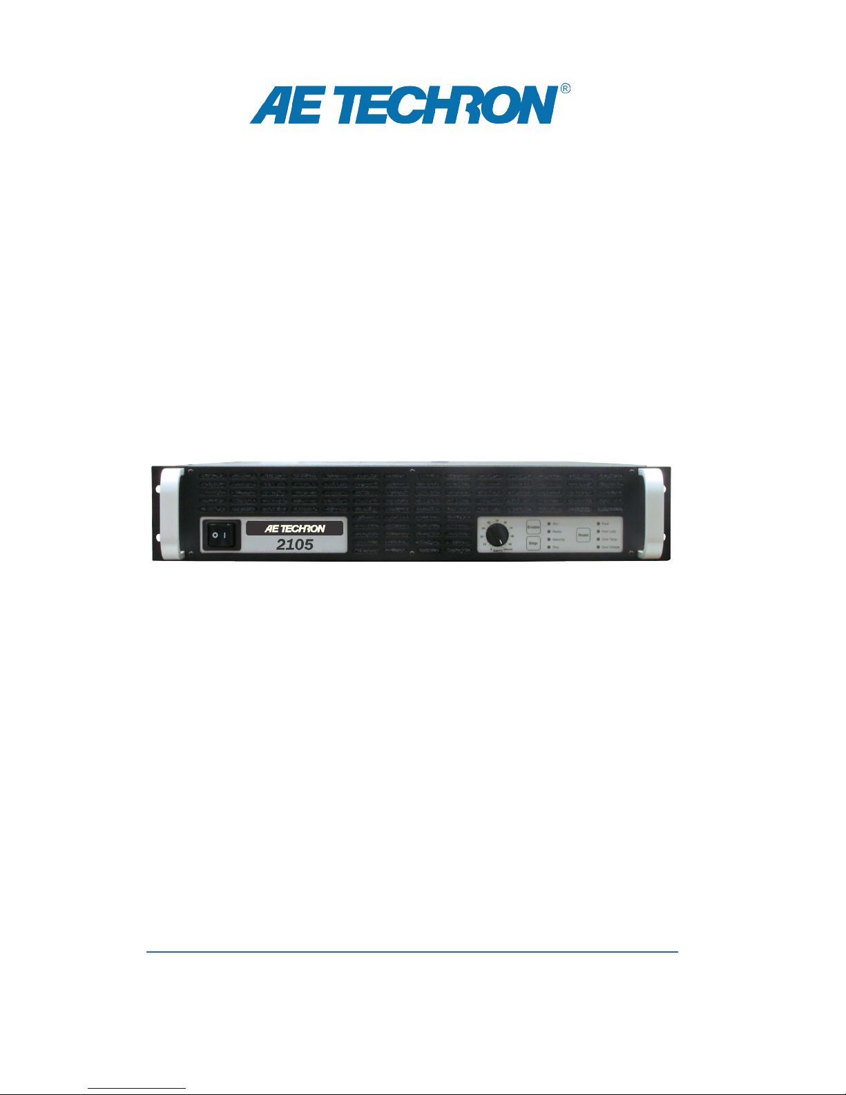
2105
Operator’s Manual
Gradient Amplier
574.295.9495 | www.aetechron.com
2507 Warren Street, Elkhart, IN 46516
Page 2

Limited One-Year Warranty
SUMMARY OF WARRANTY
AE TECHRON INC. of Elkhart, Indiana (Warrantor) war-
rants to you, the ORIGINAL COMMERCIAL PURCHASER
ONLY of each NEW AE TECHRON INC. product, for a
period of one (1) year from the date of purchase, by the
original purchaser (warranty period) that the product
is free of defects in materials or workmanship and will
meet or exceed all advertised specications for such a
product. This warranty does not extend to any subsequent purchaser or user, and automatically terminates
upon your sale or other disposition of our product.
ITEMS EXCLUDED FROM WARRANTY
We are not responsible for product failure caused by
misuse, accident or neglect. This warranty does not
extend to any product on which the serial number has
been defaced, altered, or removed. It does not cover
damage to loads or any other products or accessories
resulting from AE TECHRON INC. product failure. It does
not cover defects or damage caused by the use of unau-
thorized modications, accessories, parts, or service.
WHAT WE WILL DO
We will remedy, at our sole discretion, any defect in
materials or workmanship by repair, replacement, or
refund. If a refund is elected, you must make the defective or malfunctioning component available to us free
and clear of all liens or other encumbrances. The refund
will be equal to the actual purchase price, not includ-
ing interest, insurance, closing costs, and other nance
charges less a reasonable depreciation on the product
from the date of original purchase. Warranty work can
only be performed at our authorized service centers or
at our factory. Expenses in remedying the defect will be
borne by AE TECHRON INC., including one-way surface
freight shipping costs within the United States. (Purchaser must bear the expense of shipping the product
between any foreign country and the port of entry in the
United States and all taxes, duties, and other customs
fees for such foreign shipments.)
HOW TO OBTAIN WARRANTY SERVICE
When you notify us of your need for warranty service,
we will give you an authorization to return the product
for service. All components must be shipped in a factory
pack or equivalent which, if needed, may be obtained
from us for a nominal charge. We will take corrective actions within a reasonable time of the date of receipt of
the defective product. If the repairs made by us are not
satisfactory, notify us immediately.
DISCLAIMER OF CONSEQUENTIAL AND
INCIDENTAL DAMAGES
You are not entitled to recover from us any consequential or incidental damages resulting from any defect in
our product. This includes any damage to another product or products resulting from such a defect.
WARRANTY ALTERATIONS
No person has the authority to enlarge, amend, or
modify this warranty. The warranty is not extended by
the length of time for which you are deprived of the use
of this product. Repairs and replacement parts provided
under the terms of this warranty shall carry only the
unexpired portion of this warranty.
DESIGN CHANGES
We reserve the right to change the design of any
product from time to time without notice and with no
obligation to make corresponding changes in products
previously manufactured.
LEGAL REMEDIES OF PURCHASER
There is no warranty that extends beyond the terms
hereof. This written warranty is given in lieu of any oral
or implied warranties not contained herein. We disclaim
all implied warranties, including, without limitation, any
warranties of merchantability or tness for a particular
purpose. No action to enforce this Warranty shall be
commenced later than ninety (90) days after expiration
of the warranty period.
AE Techron, Inc.
Customer Service Department
2507 Warren Street
Elkhart, IN 46516
U.S.A.
574.295.9495
www.aetechron.com
Page 3

DECLARATION OF CONFORMITY
Technical Construction File Route
Issued By: AE Techron, Inc. For Compliance Questions Only: Larry Shank
2507 Warren Street 574-295-9495
Elkhart, IN 46516 [email protected]
Equipment Type: Industrial Power Amplifiers
Model Name: 2105
EMC Standards:
EN 61326-1: 2013 – Electrical Equipment for Measurement, Control and Laboratory use
— EMC Requirements
EN 55011: 2009 + A1: 2010 – Industrial, Scientific and Medical (ISM) radio-frequency equipment
— Radio disturbance characteristics
— Limits and methods of measurement
EN 61000-4-2: 2009 – Electromagnetic compatibility (EMC) Part 4: Testing and measurement techniques:
Electrostatic discharge immunity test
EN 61000-4-3: 2006 + A2: 2010 – Electromagnetic compatibility (EMC) Part 4: Testing and measurement techniques:
Radiated radio-frequency electromagnetic field immunity test
EN 61000-4-4: 2004 + A1: 2010 – Electromagnetic compatibility (EMC) Part 4: Testing and measurement techniques:
Electrical fast transient/burst immunity test
EN 61000-4-5: 2006 – Electromagnetic compatibility (EMC) Part 4: Testing and measurement techniques:
Surge immunity test
EN 61000-4-6: 2009 – Electromagnetic compatibility (EMC) Part 4: Testing and measurement techniques:
Immunity to conducted disturbances induced by radio frequency field
EN 61000-4-8: 2010 – Electromagnetic compatibility (EMC) Part 4: Testing and measurement techniques:
Power frequency magnetic field immunity test
Safety Standard:
BSEN61010-1:2010 (inc Corr. May 2011) – Safety requirements for electrical equipment for measurement, control, and laboratory use
I certify that the product identified above conforms to the requirements of the EMC Council Directive 2014/30/EU, and the Low Voltage Directive 2006/95/EC.
Signed:
Larry Shank
President Date of Issue: October 8, 2014
Page 4

Contents
1 Introduction ....................................................................................................................................6
1.1 Features ............................................................................................................................6
2 Amplier Unpacking and Installation ..............................................................................................7
2.1 Safety First ......................................................................................................................... 7
2.2 Unpacking .......................................................................................................................... 7
2.3 Installation .......................................................................................................................... 7
3 Connections and Startup ...............................................................................................................8
3.1 Other Operation Modes and Congurations ...................................................................... 8
3.2 Connecting the Load .......................................................................................................... 8
3.3 Connecting the Input Signal ............................................................................................... 9
3.4 Connecting the AC Supply .................................................................................................9
3.5 Start-up Procedure...........................................................................................................10
4 Amplier Operation ......................................................................................................................11
4.1 Front-Panel Controls ........................................................................................................ 11
4.2 Back-Panel Controls and Connectors .............................................................................. 16
5 Advanced Conguration ...............................................................................................................17
5.1 Conguration Access Panel .............................................................................................17
5.2 Conguration Settings Located on the Main Board .........................................................18
5.3 Conguration Settings Located on the Power Supply Board ........................................... 20
6 Applications ..................................................................................................................................23
6.1 Controlled Current Operation ........................................................................................... 23
6.2 Remote Status and Control using the SIM Interlock I/O Connector.................................27
6.3 Multi-amplier Systems .................................................................................................... 31
7 Amplier Signal Flow....................................................................................................................36
7.1 Input Signals ....................................................................................................................36
7.2 AC Mains Power ..............................................................................................................36
8 Maintenance ................................................................................................................................37
8.1 Clean Amplier Filter and Grills........................................................................................37
9 Troubleshooting ...........................................................................................................................38
9.1 Introduction & Precautions ............................................................................................... 38
9.2 Visual Inspection ..............................................................................................................38
9.3 No Signal .........................................................................................................................39
9.4 No LEDs Illuminated or No Fans .....................................................................................39
9.5 OverVoltage LED Lit ........................................................................................................39
9.6 Standby LED Remains Illuminated ..................................................................................39
9.7 Amplier Overheats (Over Temp Fault Condition) ...........................................................40
9.8 Fault LED is Illuminated ................................................................................................... 40
9.9 Factory Service ................................................................................................................ 40
10 Specications ............................................................................................................................. 42
Page 5

List of Figures
Figure 1.1 – 2105 Front Panel .......................................................................................................6
Figure 3.1 – Close-up of the Output Terminal Resistor ..................................................................9
Figure 3.2 – Controlled Voltage Hookup ........................................................................................9
Figure 3.3 – Close-up of SIM card .................................................................................................9
Figure 3.4 – Input Select switch functions on the Input Terminals ............................................... 10
Figure 3.5 – Close-up of AC Mains Outlet ...................................................................................10
Figure 3.6 – Sample of Congurations Setting Label ..................................................................10
Figure 4.1 – Power Switch ........................................................................................................... 11
Figure 4.2 – Gain Control.............................................................................................................11
Figure 4.3 – Push Buttons ...........................................................................................................11
Figure 4.5 – Main Status Indicators for Stand-Alone Ampliers...................................................12
Figure 4.4 – Main and Fault Status Indicators .............................................................................12
Figure 4.6 – Fault Status Indicators for Stand-Alone Ampliers ..................................................13
Figure 4.7 – Main Status Indicators for Multi-Amplier Systems .................................................14
Figure 4.8 – Fault Status Indicators for Multi-Amplier Systems .................................................15
Figure 4.9 – Back Panel Controls and Connectors ......................................................................16
Figure 5.1 – Access Panel Screw Locations ................................................................................17
Figure 5.2 – Main Board Location Inside Access Panel...............................................................17
Figure 5.3 – Master/Slave Setting................................................................................................18
Figure 5.4 – Gain Trim Control.....................................................................................................18
Figure 5.5 – Controlled-Voltage/Controlled-Current Mode Setting ..............................................19
Figure 5.6 – Compensation Setting .............................................................................................19
Figure 5.7 – Run Mode/Stop Mode on Power-Up Setting............................................................20
Figure 5.8 – Standby Mode on Over Load Setting.......................................................................20
Figure 5.9 – Accessing the Power Supply Board .........................................................................21
Figure 5.10 – Location of Amplier High-Voltage Transformer Sockets.......................................21
Figure 5.11 – J3 and J7 Plug Locations for High-Current Output ................................................21
Figure 5.12 – J4 and J8 Plug Locations for High-Voltage Output ................................................21
Figure 5.13 – Bi-Level Power Switch Location ............................................................................22
Figure 6.1 – Input to Output Comparison, Controlled-Voltage Operation ....................................23
Figure 6.2 – Input to Output Comparison, Controlled-Current Operation ....................................23
Figure 6.3 – Factory-installed Default RC Network......................................................................24
Figure 6.5 – Compensation Effects on Waveform .......................................................................26
Figure 6.4 – Custom Compensation Location..............................................................................26
Figure 6.6 – Square Wave Showing a Decrease in R is Required ..............................................26
Figure 6.7 – Square Wave Showing an Increase in R is Required ..............................................26
Figure 6.8 – Square Wave Showing an Increase in C is Required ..............................................26
Figure 6.9 – Remote Status and Control Pinouts ........................................................................27
Figure 6.10 – Remote Status and Reset Schematic ....................................................................28
Figure 6.11 – Remote Run/Standby Monitor ................................................................................29
Figure 6.12 – Remote Enable/Standby ........................................................................................30
Figure 6.13 – Remote Current Monitoring ...................................................................................30
Figure 6.14 – Remote Current Monitoring, Alternate Method ......................................................31
Figure 6.15 – Blanking Activation.................................................................................................31
Figure 7.1 – Board-Level Functional Block Diagram ...................................................................36
Figure 9.1 – +Vcc and –Vcc Point Locations ...............................................................................38
Figure 9.2 – Fuse F1 Location .....................................................................................................39
Figure 9.3 – Interlock I/O Connector ............................................................................................39
Page 6
1 Introduction
2105 OPERATOR’S MANUAL – SECTION 1
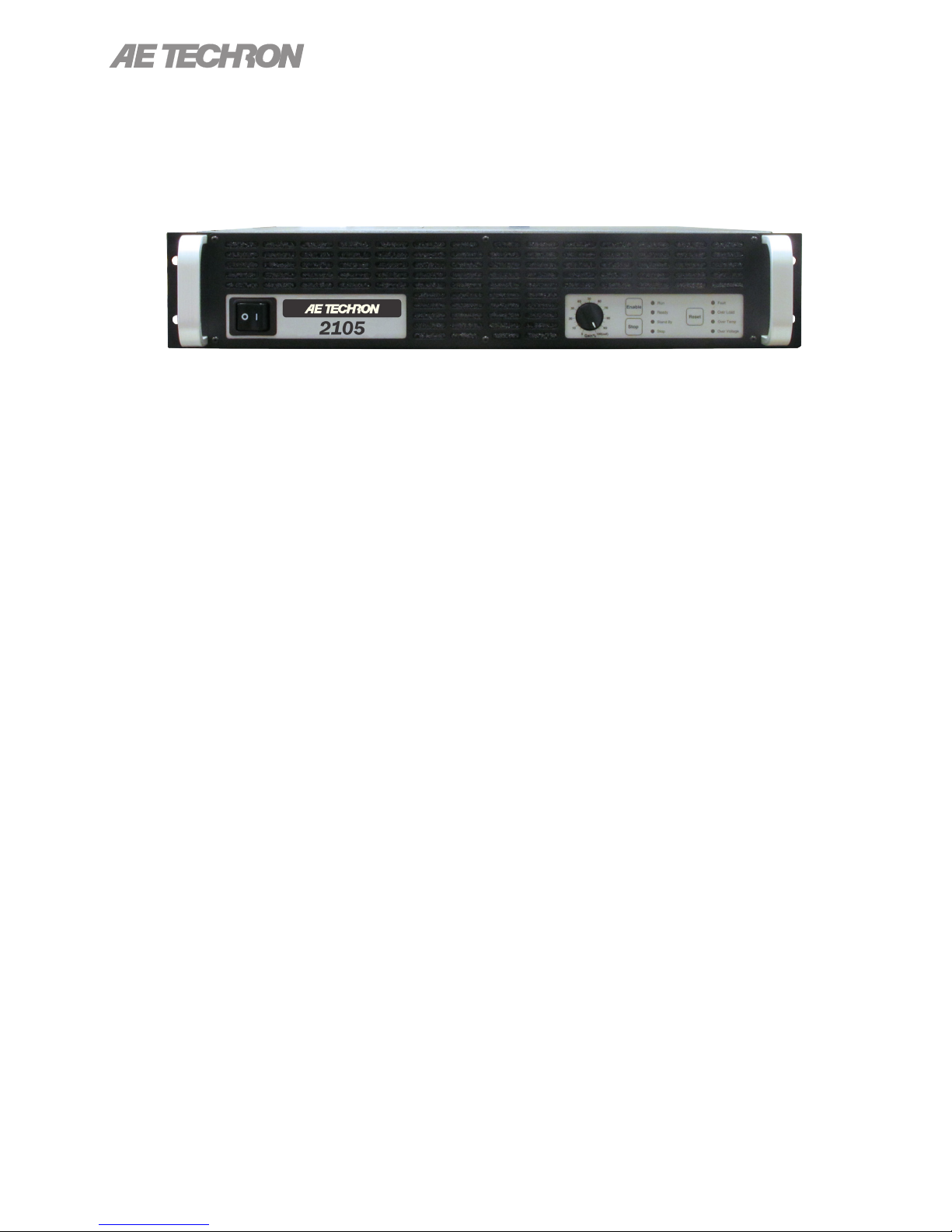
Figure 1.1 – 2105 Front Panel
The AE Techron 2105 is a high-power, DC-enabled
linear amplier and integrated power supply that
offers a wide bandwidth and exceptional control of
drift and distortion. The 2105 functions as a volt-
age or current source and operates using singlephase power, making it ideal for use in the lab or
classroom. Its linear design provides a very-low
noise oor and fast current rise times. Because
the 2105 has no ripple noise, no synching with the
console is required.
The AE Techron brand is known throughout the
world for its robust, low-noise gradient ampliers
as well as its product service and support.
1.1 Features
• Output of 50 amperes peak, 150 volts.
• 4-quadrant linear design.
• Blanking feature lowers the noise floor on the
amplifier by shutting down the output stage.
This action occurs in less than 10 µs.
• Current mode response: DC-5 kHz (compen-
sation dependent); Voltage mode response:
DC-20 kHz at rated power.
• Efficient design and light-weight chassis materials allow amplifier to occupy only 2U height,
and weigh only 41 lbs.
• Robust, linear power supply results in extreme-
ly low noise; bi-level switch design limits heat
dissipation to output devices.
• Provides precision control of output offset, DC
drift and gain linearity.
• Protection circuitry guards against input overloads, improper output connection (including
shorted and improper loads), over-temperature,
over-current, and supply voltages that are too
high or low.
• Shipped ready to operate from 120-volt (±10%)
single-phase AC mains; 220/240-volt model
available on request.
6
Information subject to change
97-2105006_4-2-15
Page 7
2105 OPERATOR’S MANUAL – SECTION 2
2 Amplier Unpacking and
Installation
The 2105 amplier is a precision instrument that
can be dangerous if not handled properly. Lethal
voltages are present in both the AC input supply
and the output of this amplier. For this reason,
safety should be your primary concern when you
setup and operate this amplier.
2.1 Safety First
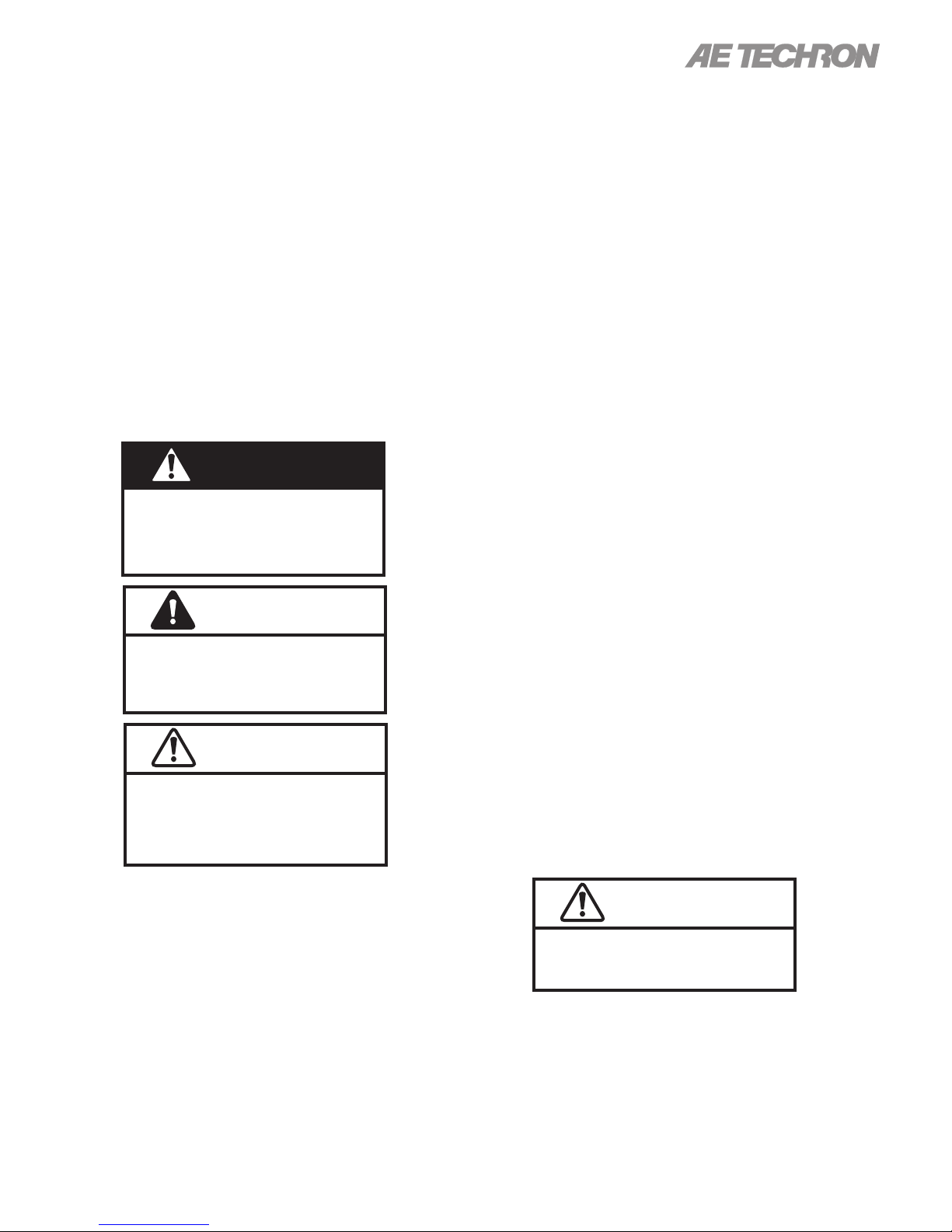
Throughout this manual special emphasis is
placed on good safety practices. The following
graphics are used to highlight certain topics that
require extra precaution.
DANGER
DANGER represents the most severe
hazard alert. Extreme bodily harm or
death will occur if these guidelines are
not followed. Note the explanation of the
hazard and instruction for avoiding it.
WARNING
WARNING alerts you to hazards that
could result in severe injury or death.
Note the explanation of the hazard and
the instructions for avoiding it.
CAUTION
CAUTION indicates hazards that could
result in potential injury or equipment
or property damage. Once again, note
the explanation of the hazard and the
instructions for avoiding it.
Along with any additional accessories purchased
by the customer, all 2105 ampliers ship with the
following:
• 2105 Amplifier
• Toolkit (contains one #2 Phillips screwdriver
and four rubber feet)
• Power Cord
• 2105 Operator’s Manual and Quick Start sheet
2.3 Installation
The 2105 ampliers are packaged in a rugged
powder-coated aluminum chassis. This chassis is
2U (rack units) tall, and has rack “ears” on each
side of the front panel for mounting to a standard
EIA (Electronic Industries Association) rack. Use
standard rack mounting hardware to mount the
amplier. Use nylon washers if you wish to protect
the powder-coat nish on the front of the amplier.
Optionally, the amplier can be placed on a
bench top; please keep in mind that the protective
powder-coating can be scratched when placed
on other equipment or on a bench top, especially
when there is dirt present. To protect the nish, a
set of rubber feet is included in the toolkit that can
be installed on the bottom of the amplier.
Allow ample space on the sides and especially
the back of the amplier for heated air to escape.
The amplier should be mounted in a rack that is
adequately ventilated and not sealed. Likewise,
the front of the amplier should be unobstructed to
allow cool air to enter the amplier.
2.2 Unpacking
All ampliers are tested and inspected for damage before leaving the factory. Carefully unpack
and inspect the amplier for damage. Please note
any damage for future reference and notify the
shipping company immediately if damage is
found. Also, please save the shipping carton and
materials as evidence of damage and/or for returning the amplier for repair.
97-2105006_4-2-15
Do not operate the amplier in a small
sealed chamber of any kind. Improper
operations and overheating will result.
Information subject to change
CAUTION
7
Page 8
2105 OPERATOR’S MANUAL – SECTION 3
3 Connections and Startup
This section details the wiring and startup procedures for a single 2105 amplier operating in
Controlled-Voltage mode (factory default). Before
connecting the amplier, make sure the AC power
cord is unplugged.
WARNING
ELECTRIC SHOCK HAZARD.
Output potentials can be lethal. Make
connections only with AC Power OFF
and input signals removed.
3.1 Other Operation Modes and
Congurations
The 2105 amplier can be eld-congured for
operation in a number of different ways. These
would include Controlled-Voltage or ControlledCurrent mode, and it also can be congured for
operation as a part of a multi-amplier system.
These alternate congurations may require special
output wiring and/or additional components.
3.1.1 Controlled-Current Operation of a
Stand-Alone Amplier
If your application requires Controlled-Current
operation, the 2105 amplier rst should be wired
and tested in Controlled-Voltage mode to verify
that the amplier and input signal are operating
correctly. Once proper operation is conrmed,
refer to the “Applications” section of this manual
for instructions on conguring and operating your
amplier in Controlled-Current mode.
3.1.2 Multi-Amp Operation
If your application requires multi-amp operation for
increased voltage or current, each amplier should
rst be wired and tested individually in ControlledVoltage mode to ensure proper operation.
For Series operation in Controlled-Voltage
mode, refer to the Multi-Amp Conguration
Guide (available for download from aetechron.
com) for information on Series system congura-
tion.
For Series operation in Controlled-Current
mode, you should select one amplier to be operated as the “Master” amplier of the system, and
then refer to the “Applications” section of this
manual for instructions on conguring this amplier for operation in Controlled-Current mode. After
the Master amplier is congured and tested for
Controlled-Current operation, refer to the Multi-
Amp Conguration Guide (available for download from aetechron.com) for information on Series
system conguration.
For Parallel operation in Controlled-Voltage
mode, refer to the Multi-Amp Conguration
Guide (available for download from aetechron.com)
for information on Parallel system conguration.
For Parallel operation in Controlled-Current
mode, please contact AE Techron Technical
Support for assistance.
3.2 Connecting the Load
3.2.1 Preparation and Cautions
Before connecting the amplier, make sure the
AC power is disconnected.
Always use the appropriate wire size and insulation for the maximum current and voltage expected
at the output. Never connect the output of the
amplier to any other model amplier, power supply, signal source, or other inappropriate load; re
can result.
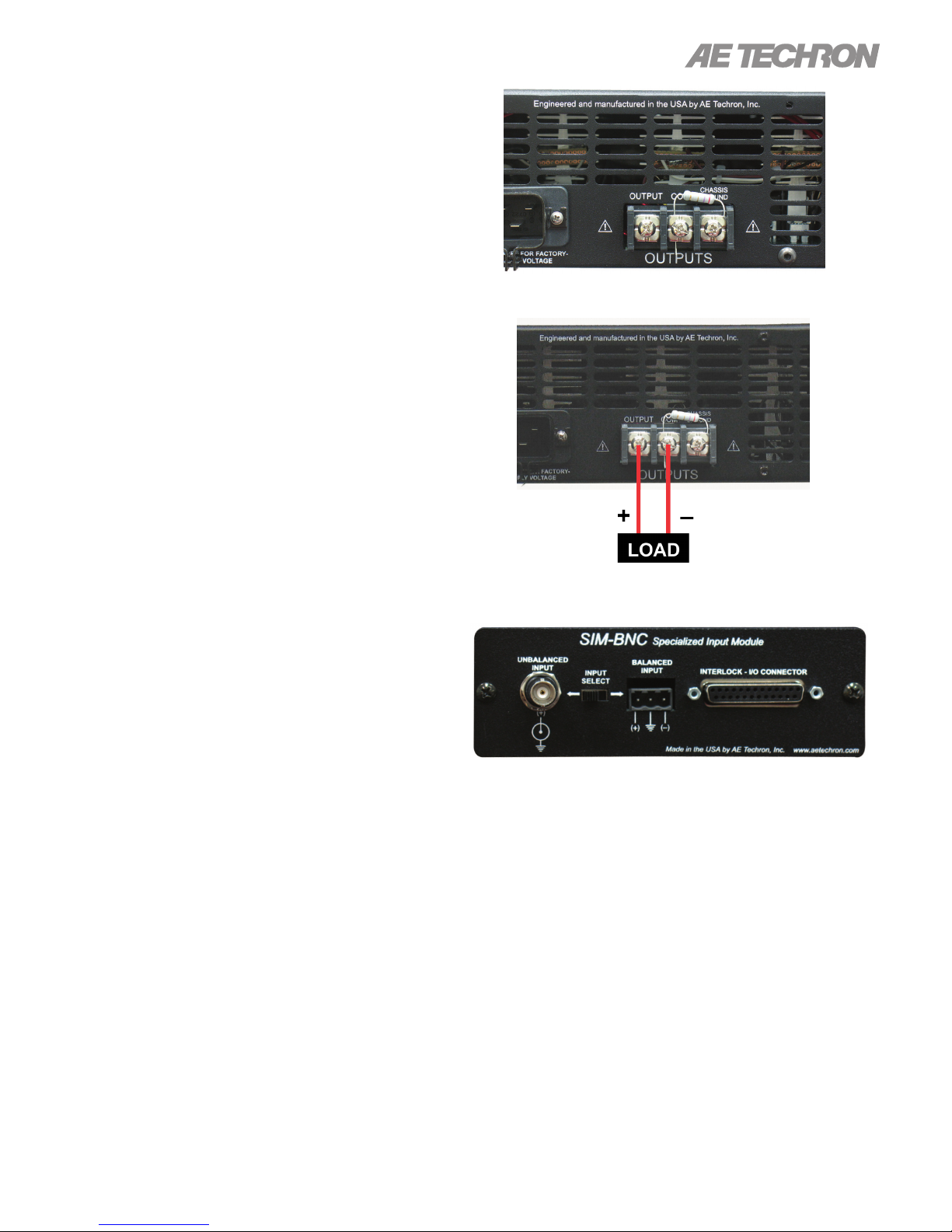
NOTE: The 2105 amplier comes with a factoryinstalled 2.7-ohm, 2W, 5%, metal-oxide resistor connecting the terminals marked “COM and
“CHASSIS GROUND” (see Figure 3.1). This
resistor should NOT be removed except when the
amplier is being used as a Slave amplier in a
Series multi-amp system. WARNING: Removing
this resistor can cause dangerous output and/
or damage to the load.
3.2.2 Connecting the Outputs
Connection to the output of the amplier is to a
3-position terminal strip with #8 screws. Wires
8
Information subject to change
97-2105006_4-2-15
Page 9
2105 OPERATOR’S MANUAL – SECTION 3
terminated with #8 to ¼ in. ring terminals, tinned
wires up to 10GA in size, or bus bars with 0.20 in.
(5 mm) OD holes (minimum) up to 0.50 in. (12.7
mm) OD holes (maximum) are recommended
when connecting to the output terminals.
Connect the load across the terminals marked
“OUTPUT” (positive) and “COM” (negative/
ground). The third terminal, “CHASSIS GROUND”
is connected to the amplier chassis/power cord
ground and can be connected to an external
ground point such as the rack chassis. See Figure
3.2.
3.3 Connecting the Input Signal
The signal is connected to the amplier through a
“SIM” (Specialized Input Module) located on the
amplier back panel (see Figure 3.3). The SIM
card offers the choice of BNC or terminal block
input connectors.
Figure 3.1 – Close-up of the Output Terminal Resistor
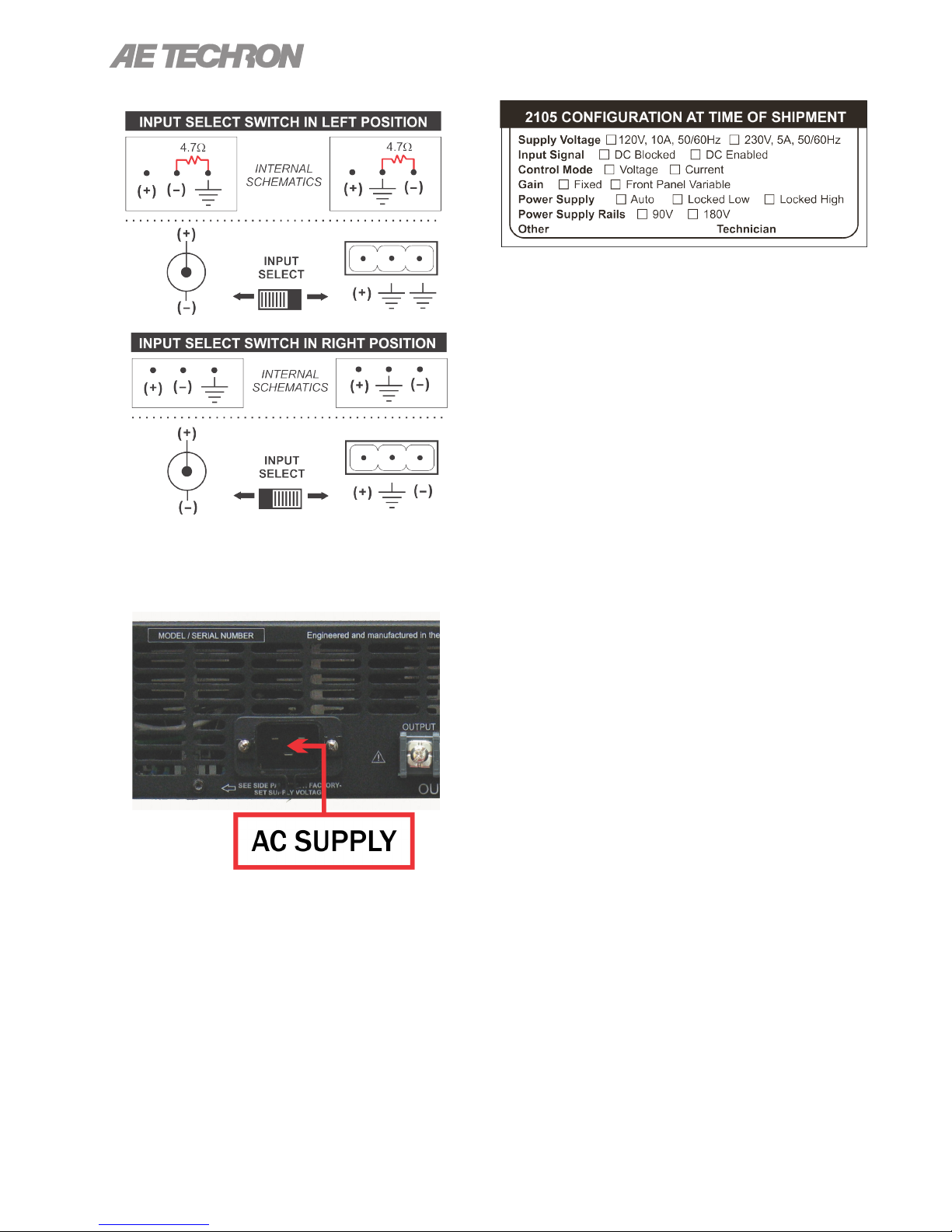
The Input Select switch, located on the SIM module between the input connectors, allows convenient selection of balanced or unbalanced input
wiring and also can function as a ground-lift switch
for the BNC input connector. The Input Select
switch functions by connecting/ disconnecting the
inverting (–) pin on each input connector to the
amplier ground through a 4.7-ohm resistor (see
Figure 3.4). When the Input Select switch is in the
LEFT position, the shield on the BNC connector
and the inverting (–) pin on the terminal block connector are tied to the amplier ground, allowing the
connectors to be used for Unbalanced input wiring.
When the Input Select switch is in the RIGHT
position, the inverting (–) pin on the terminal block
connector is oating, allowing the connector to be
used for Balanced input wiring.
IMPORTANT: The Input Select switch can also
function as a Ground Lift switch for the BNC
Input connector. If circulating currents/ground
loops/60-Hz Hum occur when using the BNC
Input, move the Input Select switch to the right
to lift the ground on the connector.
Figure 3.2 – Controlled Voltage Hookup
Figure 3.3 – Close-up of SIM card
We recommend that you use cables that are high
quality and shielded to minimize noise and to
guard against possible feedback.
Note: See the “Applications” section for informa-
tion on using the Interlock – I/O Connector located
on the SIM card.
3.4 Connecting the AC Supply
The power cord connects to a standard 20 amp
3-pin IEC-type male connector on the back panel
(see Figure 3.5). Make sure the Breaker/Switch on
97-2105006_4-2-15
Information subject to change
9
Page 10
2105 OPERATOR’S MANUAL – SECTION 3
Figure 3.6 – Sample of Congurations Setting Label
Review the factory-set supply voltage and amplier conguration detailed on the label placed on
the side of the amplier (see Figure 3.6). This
conguration can be changed by the user. See
the “Advanced Conguration” section for more
information.
3.5 Start-up Procedure
3.5.1 Voltage-Mode Operation
Figure 3.4 – Input Select switch functions on the
Input Terminals
Figure 3.5 – Close-up of AC Mains Outlet
the front panel is switched to the OFF (O) position.
Make sure the power cord is inserted and seated
fully into the IEC connector by moving it slightly
back and forth and up and down while pushing
in. The power cord is relatively stiff and should be
routed so that there is no excessive force pulling to
the sides or up or down that would stress the pins
or internal connections. Tighten the cord strain
relief screw to lock the power cord in place.
Perform the following steps to startup and operate
your amplier in Controlled-Voltage.
1. Turn down the level of your signal source.
2. Turn down the gain control of the amplier.
3. Depress the POWER switch to turn the
amplier ON.
4. Wait for the yellow READY and green RUN
LEDs to illuminate.
5. Adjust the level of your input signal source
to achieve the desired output level.
6. Turn up the Gain control on the amplier
until the desired voltage or power level is
achieved.
7. Adjust the input signal level to achieve the
desired output level.
3.5.1 Current-Mode Operation
Before conguring your amplier for Current mode
operation, it is important to verify the amplier is
operating correctly in Voltage mode. Perform the
steps provided in the “Voltage-Mode Opera-
tion” Start-up Procedure to test the amplier in
Controlled-Voltage mode. Use care if your load is
very-low impedance since high currents can be
caused by low input levels. Then refer to the “Applications” section of this manual for instructions
on Controlled-Current conguration and operation.
10
Information subject to change
97-2105006_4-2-15
Page 11
2105 OPERATOR’S MANUAL – SECTION 4
4 Amplier Operation
4.1 Front-Panel Controls
This section provides an overview of Front-Panel
controls and indicators found on the 2105.
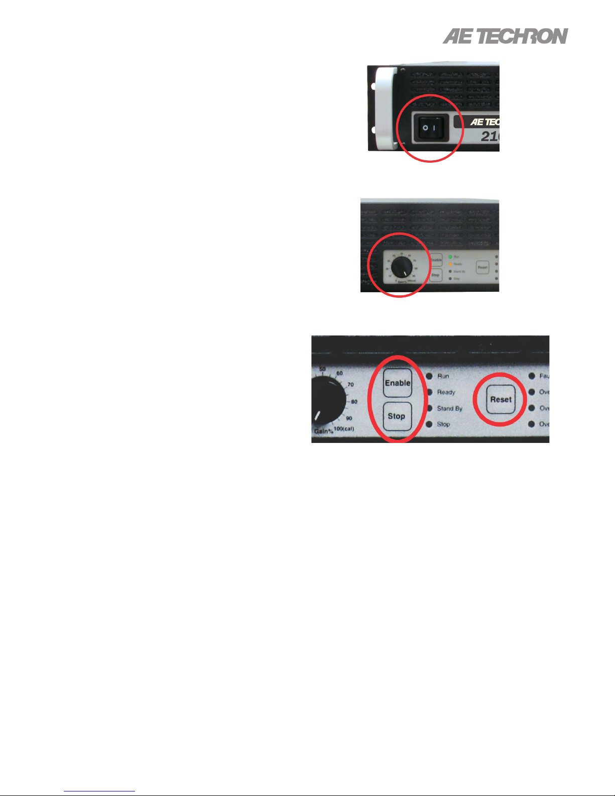
4.1.1 Power Switch
The Power Switch controls the AC mains power to
the amplier. Switch to the ON position (|) to turn
the amplier on. Switch to the OFF position (O) to
turn the amplier off. See Figure 4.1.
The Power Switch also serves as a Breaker. When
the Breaker is tripped, the Power Switch moves to
a neutral position between ON and OFF. To reset
the Breaker, turn the amplier OFF (O) and then
turn it back ON (I).
4.1.2 Gain Control
The Gain Control Knob increases/decreases the
gain from 0 – 100% of the overall Gain (factory
default Gain is 20V/V in voltage mode and 5A/V
in current mode). See Figure 4.2. See the “Ad-
vanced Conguration” section for information on
how to make the amplier xed-gain.
4.1.3 Push Buttons
The 2105 provides three front-panel soft-touch
Push Buttons (see Figure 4.3):
Enable – For stand-alone ampliers, Enable will
release the amplier from Standby mode and
place the amplier in Run mode (both Ready and
Run LEDs will be lit). When the amplier is placed
in Run mode, the amplier will amplify the input
signal. If an amplier is disabled using a Remote
Standby application, the amplier will be placed in
Ready mode (both Ready and Standby LEDs will
be lit). To return the amplier to Run mode, release
the Standby condition using the remote switch.
See the “Applications” section of this manual for
more information on remote amplier operation.
By default, the amplier will automatically be
Enabled and enter Run mode on power-up. To
change the factory-default setting and congure
Figure 4.1 – Power Switch
Figure 4.2 – Gain Control
Figure 4.3 – Push Buttons
the amplier to power-up in Standby mode, please
see the “Advanced Conguration” section.
In multi-amp systems that have been congured
to start up in Run mode (factory default setting),
when an amplier is powered on, the amplier will
be placed in Ready mode (Ready and Standby
LEDs lit) and remain in Ready mode until all ampliers in the system have been powered on. The
system will automatically proceed to Run mode
when all ampliers in the system are powered on
and achieve Ready mode.
In multi-amp systems that have been congured
to start up in Standby mode, when an amplier is
powered on, the amplier will be placed in Standby
mode (Stop and Standby LEDs lit). When the
97-2105006_4-2-15
Information subject to change
11
Page 12
Enable button is pressed on each amplier, that
amplier will be placed in Ready mode (Ready and
Standby LEDs lit) and remain in Ready mode until
all ampliers in the system have been Enabled.
The system will automatically proceed to Run
mode when all ampliers in the system achieve
Ready mode.
Stop – For stand-alone ampliers, Stop will place
the amplier in Standby mode (both Standby and
Stop LEDs will be lit). When the amplier is part of
a multi-amp system, pressing the Stop button on
any amplier in the system will place all ampliers
in Standby mode. When an amplier is in Standby
mode, the low-voltage transformer is energized but
the high-voltage transformers are not.
2105 OPERATOR’S MANUAL – SECTION 4
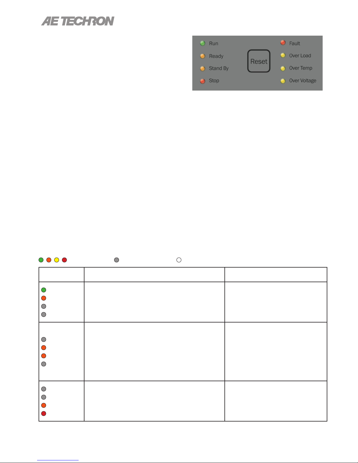
Figure 4.4 – Main and Fault Status Indicators
all of the ampliers to Run mode if the condition
causing the fault condition has been cleared; however, pressing the Reset button on other ampliers
in the system will NOT clear the fault condition.
Refer to the “Fault Status Indicators” section for
information on how to clear fault conditions and
restore amplier operation.
Reset – For stand-alone ampliers, when the amplier has stopped due to a fault condition, pressing the Reset button will return the amplier to Run
mode if the condition causing the fault condition
has been cleared. When the amplier is part of a
multi-amp system, pressing the Reset button on
the amplier reporting the fault condition will return
4.1.4 Main Status Indicators
Four Main Status indicators are located on the
amplier’s front-panel (see Figure 4.4). These
LEDs monitor the internal conditions of the amplier and indicate the current state of operation. The
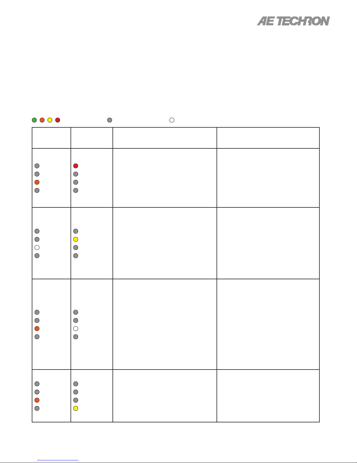
chart in Figure 4.5 details the operational modes
indicated by the Main Status indicators.
Figure 4.5 – Main Status Indicators for Stand-Alone Ampliers
Indicator is lit Indicator is not lit Indicator may be lit
Main Status
Indicators State of Operation
Run
Ready
Standby
Stop
Run
Ready
Standby
Stop
Run
Ready
Standby
Stop
Run mode: The amplier’s high-voltage transformers
are energized and the unit will amplify the input signal.
Run mode is initiated by: (1) the Enable push button, or
(2) when the amplier powers up in Run mode (factory
default). See the “Advanced Conguration” section for
more information.
Standby mode: Standby mode indicates that the am-
plier is functioning properly and all Fault Status modes
are clear, but it is being held in Standby by an external
condition. As congured from the factory (Run mode on
startup), the amplier will enter Standby mode briey
after powering up, and then will move automatically into
Run mode. In Standby mode, the amplier’s low-voltage
transformer is energized but the high-voltage transformers
are not.
Stop mode: When the Stop button on the amplier front
panel is pressed, the amplier will enter Stop mode. The
amplier may also enter Stop mode after powering up if
the amplier is congured to enter Stop mode on startup.
In Stop mode, the amplier’s low-voltage transformer is
energized but the high-voltage transformers are not.
Action Needed to Return to Run
Mode
N/A
If the amplier remains in Standby mode,
it is being held in Standby by remote control through the SIM Interlock I/O connector. Open the Enable/Standby switch to
clear this remote Standby condition and
return the amplier to Run mode. See the
“Applications” section of this manual
for more information on remote amplier
operation.
To release the amplier from Stop mode,
press the Enable button.
12
Information subject to change
97-2105006_4-2-15
Page 13
2105 OPERATOR’S MANUAL – SECTION 4
4.1.5 Fault Status Indicator
Four Fault Status indicators are located on the
amplier front panel (see Figure 4.4). These LEDs
monitor the internal conditions of the amplier
and will illuminate when a fault condition occurs.
Depending on the fault condition and the congu-
ration of the unit, the amplier may be placed in
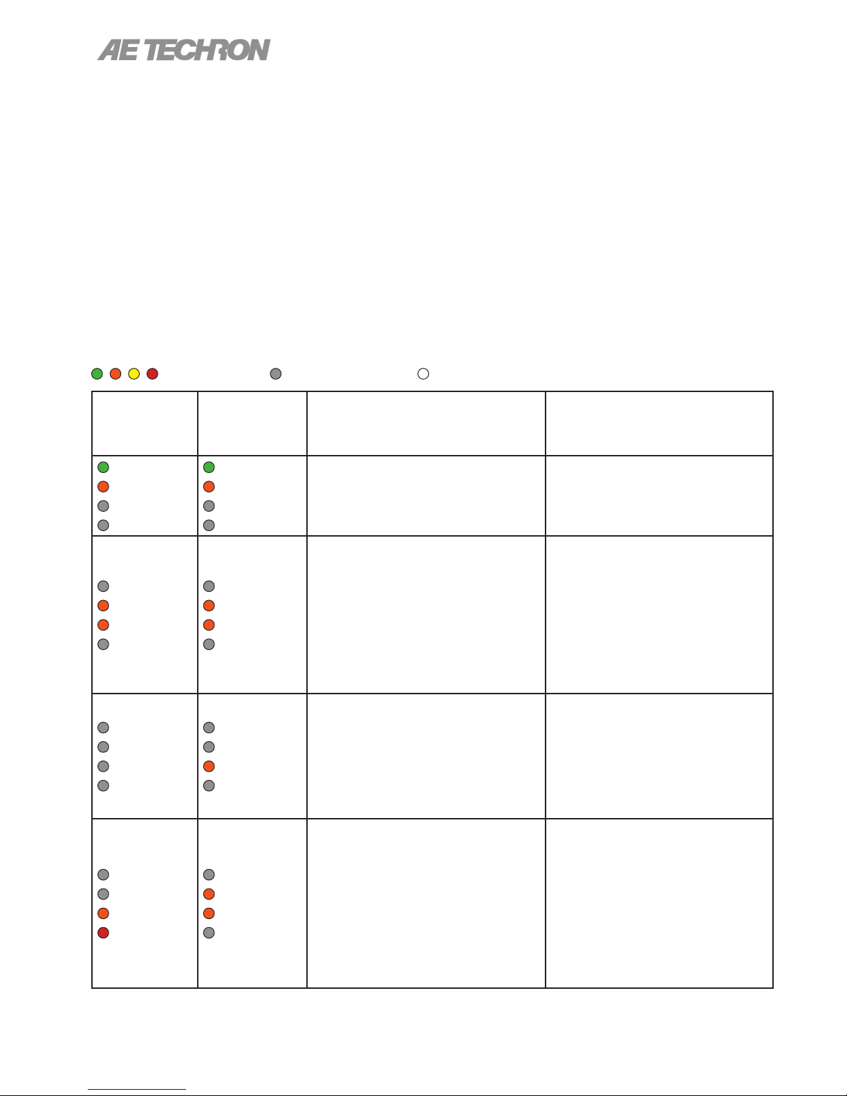
Standby mode when a fault condition occurs. Refer to the chart in Figure 4.6 to determine the fault
condition being indicated and the action required
to clear the fault condition.
Figure 4.6 – Fault Status Indicators for Stand-Alone Ampliers
Indicator is lit Indicator is not lit Indicator may be lit
Main Status
Indicators
Run
Ready
Standby
Stop
Run
Ready
Standby
Stop
Run
Ready
Standby
Stop
Run
Ready
Standby
Stop
Fault Status
Indicators State of Operation
Output Fault status: This indicates
that an Output Fault condition has oc-
Fault
Over Load
Over Temp
Over Voltage
Fault
Over Load
Over Temp
Over Voltage
Fault
Over Load
Over Temp
Over Voltage
Fault
Over Load
Over Temp
Over Voltage
curred and the amplier has been placed
in Standby mode. The Fault indicator
will light under two conditions: 1) Highfrequency oscillation is causing high
shoot-through current; or 2) An output
transistor has shorted, causing the output
fault condition.
Over Load status: This indicates that
the output of the amplier could not follow
the input signal due to voltage or current
limits. Under normal operation with the
factory-default settings, an Over Load
condition will not place the amplier in
Standby mode. If the amplier has been
congured to be forced to Standby on
Over Load, the amplier will be placed in
Standby mode when the Over Load indicator lights.
Over Temp status: The amplier
monitors the temperature inside the highvoltage transformers, low-voltage transformer and in the output stage heat sinks.
The Over Temp indicator will light and the
amplier will be placed in Standby mode
when the temperature sensors detect a
condition that would damage the amplier. If the Over Temp pulse is extremely
short, as in the case of defective wiring or
switches, the Over Temp LED may be lit
too briey to observe.
Over Voltage status: This indicates
that the AC mains voltage is more than
+10% of nominal. The amplier will be
forced to Standby when an Over Voltage
condition occurs. When the Over Voltage
condition is cleared, the amplier will auto-
matically return to Run mode.
Action Needed to Clear Fault
Condition and Return to
Run Mode
This fault condition cannot be cleared
using the front-panel Reset button. See
the “Trouble-
shooting” section for more informa-
tion on diagnosing and clearing this fault
condition.
To remedy the Over Load fault during
operation, turn down the level of the input
signal until the Over Load indicator turns
off. To clear an Over Load fault condition
when the amplier is forced to Standby,
turn down the level of the input signal,
then push the Reset button.
To reset after an Over Temp fault has
occurred, make sure the fans are running,
and then remove the input signal from the
amplier. Allow the fans to run for about
5 minutes until the amplier automatically returns to Run mode. If the amplier
has been congured for Standby mode
on Over Temp, then the amplier will not
automatically return to Run mode. In that
case, push the Reset button to return the
amplier to Run mode. See the “Trouble-
shooting” section for information on cor-
recting the cause of an Over Temp fault
condition.
To clear an Over Voltage fault condition,
the AC mains must be brought down to
the nominal value. If the amplier does
not return to Run mode when the Over
Voltage condition has cleared, the amplier may require servicing. Please see
the “Troubleshooting” section for more
information.
97-2105006_4-2-15
Information subject to change
13
Page 14
2105 OPERATOR’S MANUAL – SECTION 4
4.1.6 Main Status Indicators for
Multi-amplier Systems
The Main Status indicators on each amplier in
a multi-amp system are used to determine the
operational status of the amplier. When evaluated
along with the statuses of other ampliers in the
system, the Main Status indicators can be used
to determine the system status and the action
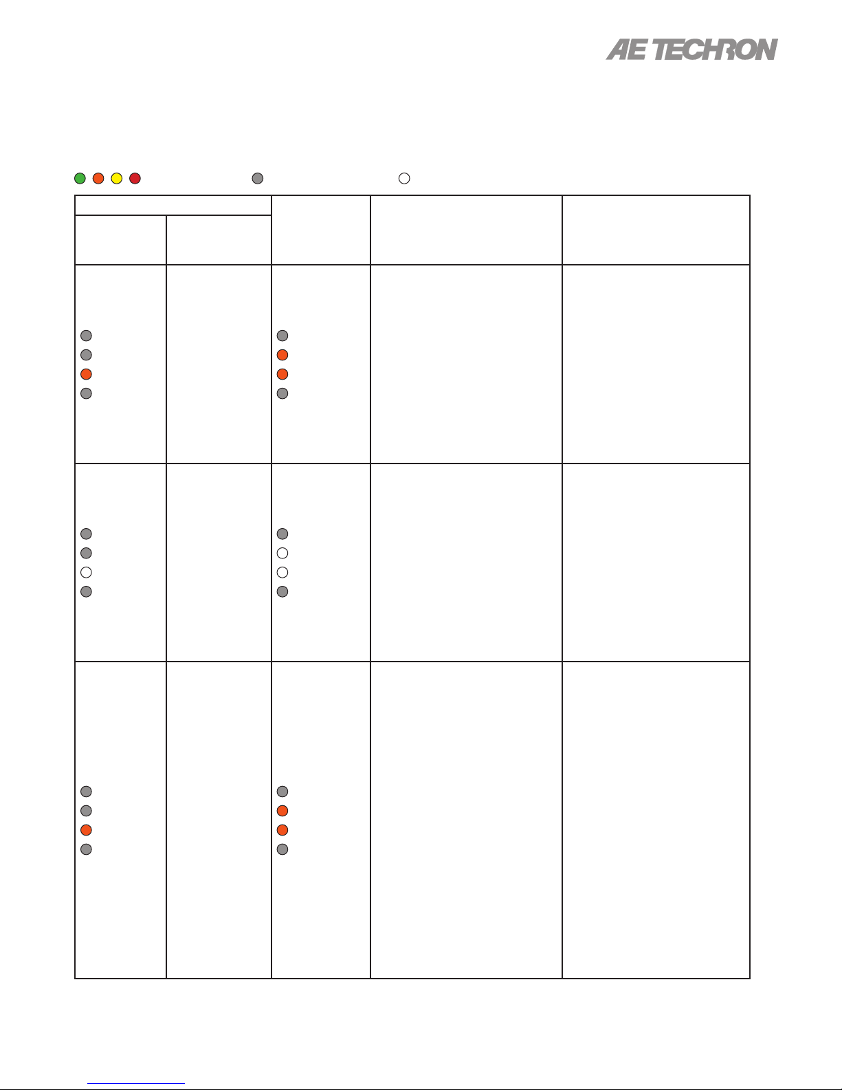
required to return the system to Run mode. See
Figure 4.7.
4.1.7 Fault Status Indicators for
Multi-Amp Systems
The four Fault Status indicators located on each
amplier’s front panel are used to monitor the
internal conditions of the amplier and will illuminate when a fault condition occurs. All ampliers in
the system may be placed in Standby mode when
a fault condition occurs, depending on the fault
condition and the conguration of the system. Typi-
cally, the system can be released from Standby
mode by pressing the Reset button on the ampli-
Figure 4.7 – Main Status Indicators for Multi-Amplier Systems
Indicator is lit Indicator is not lit Indicator may be lit
Main Status
of One or
More Amps in
the System
Run
Ready
Standby
Stop
Run
Ready
Standby
Stop
Main Status of
Other Amps in
the System State of Operation
Run
Ready
Standby
Stop
Run
Ready
Standby
Stop
Run mode: All of the ampliers in the
system are in Run mode. The ampliers’
high-voltage transformers are energized
and the system will amplify the input
signal.
Remote Standby Condition: All of
the ampliers in the system are being
held in Standby mode by an external
condition. In Standby mode, the ampli-
ers’ low-voltage transformers are energized but the high-voltage transformers
are not.
Action Needed to Return to
Run Mode
N/A
If the ampliers remain in Standby
mode, the system is being held in
Standby by remote control through the
SIM Interlock I/O connector. Open the
Enable/Standby switch to clear this
remote Standby condition and return
the system to Run mode. See the
”Applications” section of this manual
for more information on remote ampli-
er operation.
Run
Ready
Standby
Stop
Run
Ready
Standby
Stop
Run
Ready
Standby
Stop
Run
Ready
Standby
Stop
14
System Not Ready: If one or more
of the ampliers has no LEDs lit, the
amplier has no power or has not been
turned on, and the other ampliers in the
system will be held in Standby mode.
In Standby mode, the amplier’s lowvoltage transformer is energized but the
high-voltage transformers are not.
Stop mode: When the Stop button on
any amplier in the system is pressed,
that amplier will enter Stop mode and
all other ampliers will enter Standby
mode. The system may also enter Stop
mode after powering up if one or more
ampliers in the system is congured
to enter Stop mode on startup. In Stop
mode, the amplier’s low-voltage transformer is energized but the high-voltage
transformers are not.
Information subject to change
Make sure all ampliers have AC
power and have been turned on. When
all ampliers attain Standby status, all
ampliers in the system will simultane-
ously be placed in Run mode.
To release the system from Stop mode,
press the Enable button on the ampli-
er displaying the Stop mode status.
97-2105006_4-2-15
Page 15
2105 OPERATOR’S MANUAL – SECTION 4
er displaying the Fault status. Refer to the chart
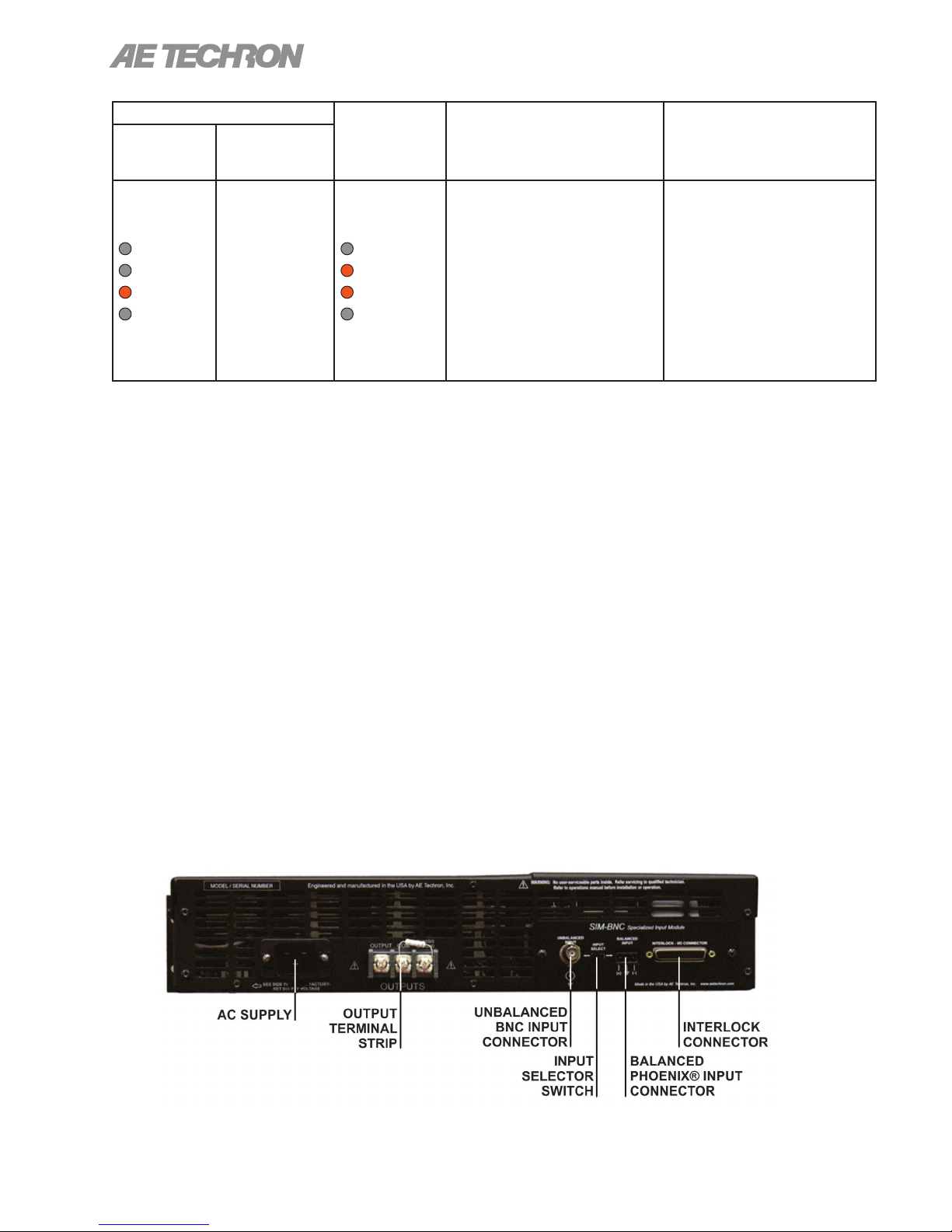
in Figure 4.8 to determine the fault condition being
indicated and the action required to clear the fault
condition and return the system to Run mode.
Figure 4.8 – Fault Status Indicators for Multi-Amplier Systems
Indicator is lit Indicator is not lit Indicator may be lit
One or More Amps in System
Fault Status
Main Status
Indicators
Run
Ready
Standby
Stop
Run
Ready
Standby
Stop
Run
Ready
Standby
Stop
Reported on
LCD Display
WARNING!
OUTPUT DE-
VICE FAULT
WARNING!
OVERLOAD
WARNING!
OVERTEMP
Main Status
Indicators of
Other Amps
in System State of Operation
Output Device Fault status: This indicates that an Out-
put Fault condition has occurred
in the amplier displaying the
Run
Ready
Standby
Stop
Run
Ready
Standby
Stop
Run
Ready
Standby
Stop
Fault status, and the system has
been placed in Standby mode.
The Fault indicator will light
under two conditions: 1) Highfrequency oscillation is causing
high shoot-through current; or 2)
An output transistor has shorted,
causing the output fault condition.
Overload status: This
indicates that the output of the
system could not follow the input
signal due to voltage or current
limits. Under normal operation
with the factory-default settings,
an Overload condition will not
place the system in Standby
mode. If the system has been
congured to be forced to Standby on Overload, the system
will be placed in Standby mode
when the Fault indicator lights.
Overtemp status: Each am-
plier in the system monitors the
temperature inside the high-voltage transformers, low-voltage
transformer and in the output
stage heat sinks. The Overtemp
indicator will light and the system
will be placed in Standby mode
when the temperature sensors
detect a condition that would
damage the amplier system. If
the Overtemp pulse is extremely
short, as in the case of defective
wiring or switches, the Fault LED
may be lit too briey to observe.
Action Needed to Clear
Fault Condition and Return to Run Mode
This fault condition cannot be
cleared using the front-panel
Reset button. See the ”Troubleshooting” section for more
information on diagnosing and
clearing this fault condition.
To remedy the Overload fault
during operation, turn down the
level of the input signal until
the Overload indicator turns
off. To clear an Overload fault
condition when the amplier is
forced to Standby, turn down
the level of the input signal,
then push the Reset button on
the amplier(s) displaying the
Overload status.
To reset after an Overtemp
fault has occurred, make sure
the amplier fans in all ampliers are running, and then
remove the input signal from
the system. Allow the fans to
run for about 5 minutes until the
system automatically returns to
Run mode. If the system has
been congured for Standby
mode on Overtemp, then the
system will not automatically return to Run mode. In that case,
push the Reset button on any
amplier displaying the Overtemp status to return the system
to Run mode. Please see the
”Troubleshooting” section
for information on correcting
the cause of an Overtemp fault
condition.
97-2105006_4-2-15
Information subject to change
15
Page 16
2105 OPERATOR’S MANUAL – SECTION 4
One or More Amps in System
Fault Status
Main Status
Indicators
Run
Ready
Standby
Stop
Reported on
LCD Display
WARNING!
OVERVOLTAGE
Main Status
Indicators of
Other Amps
in System State of Operation
Overvoltage status: This
indicates that the AC mains
voltage is more than +10% of
Run
Ready
Standby
Stop
nominal. All ampliers in the
system will be forced to Standby
when an Overvoltage condition
occurs. When the Overvoltage
condition is cleared, the system
will automatically return to Run
mode.
4.2 Back-Panel Controls
and Connectors
This section provides an overview of Back-Panel
controls and connectors found on the 2105 ampli-
er. Please refer to Figure 4.9 for visual locations.
AC Supply - Standard 20 amp 3-pin IEC-type
male connector.
Output Terminal Strip - Connect output lines from
the load to this 3-position terminal strip with 5 mm
screws. It accepts up to #10 AWG wire.
BNC Input Connector - This input option provides
a standard unbalanced input. It can also be used
as a balanced input.
Input Selector Switch – When the Input Select
switch is in the LEFT position, the shield on the
BNC connector and the inverting (–) pin on the
terminal block connector are tied to the amplier
Action Needed to Clear
Fault Condition and Return to Run Mode
To clear an Overvoltage fault
condition, the AC mains must
be brought down to the nominal value. If the system does
not return to Run mode when
the Overvoltage condition has
cleared, one or more ampliers
may require servicing. Please
see the “Troubleshooting”
section for more information.
ground through a 4.7-ohm resistor, allowing the
connectors to be used for Unbalanced input wiring. When the Input Select switch is in the RIGHT
position, the inverting (–) pin on the terminal block
connector is oating, allowing the connector to be
used for Balanced input wiring. The Input Select
switch also functions as a Ground Lift switch for
the BNC input connector.
Terminal Block Input Connector - This input option provides a balanced input. It can also be used
as an unbalanced input.
Interlock Connector - This 25-pin, D-sub connector is used for interlocking and combining functions
in a multi-amp system. It can also be used for re-
mote control and monitoring applications (see the
”Applications” section for more information).
Figure 4.9 – Back Panel Controls and Connectors
16
Information subject to change
97-2105006_4-2-15
Page 17
2105 OPERATOR’S MANUAL – SECTION 5
5 Advanced Conguration
The 2105 amplier was designed to offer exceptional versatility in operation. You can choose from
a range of eld-congurable options, including:
• Operate as a stand-alone amplifier or as part of
a multiple-amplifier system.
• Operate with variable gain control or at a fixed
gain setting of 20.
• Select Controlled-Current or Controlled-Voltage
modes of operation.
• Trigger Standby mode when specified fault
conditions occur during operation.
• Select the Stop mode state at power-up, or go
immediately to the Run mode state at power-up.
• Configure for use in high voltage applications,
high current applications, or for applications
requiring mid-level amounts of both voltage
and current.
Your 2105 amplier has been pre-congured to
your specications before shipping from the factory. These initial settings are detailed on your
Proof of Performance sheet and on a label located
on the side of the amplier.
WARNING
Do not attempt to access the Main Board
while the amplier is running. Turn the
amplier off and disconnect the AC
Mains before removing the amplier
front panel.
CAUTION
After turning the amplier off, let the unit
sit for 3-5 minutes before removing the
front panel. This will allow the electrical
charge in the Power Supply capacitors
to discharge.
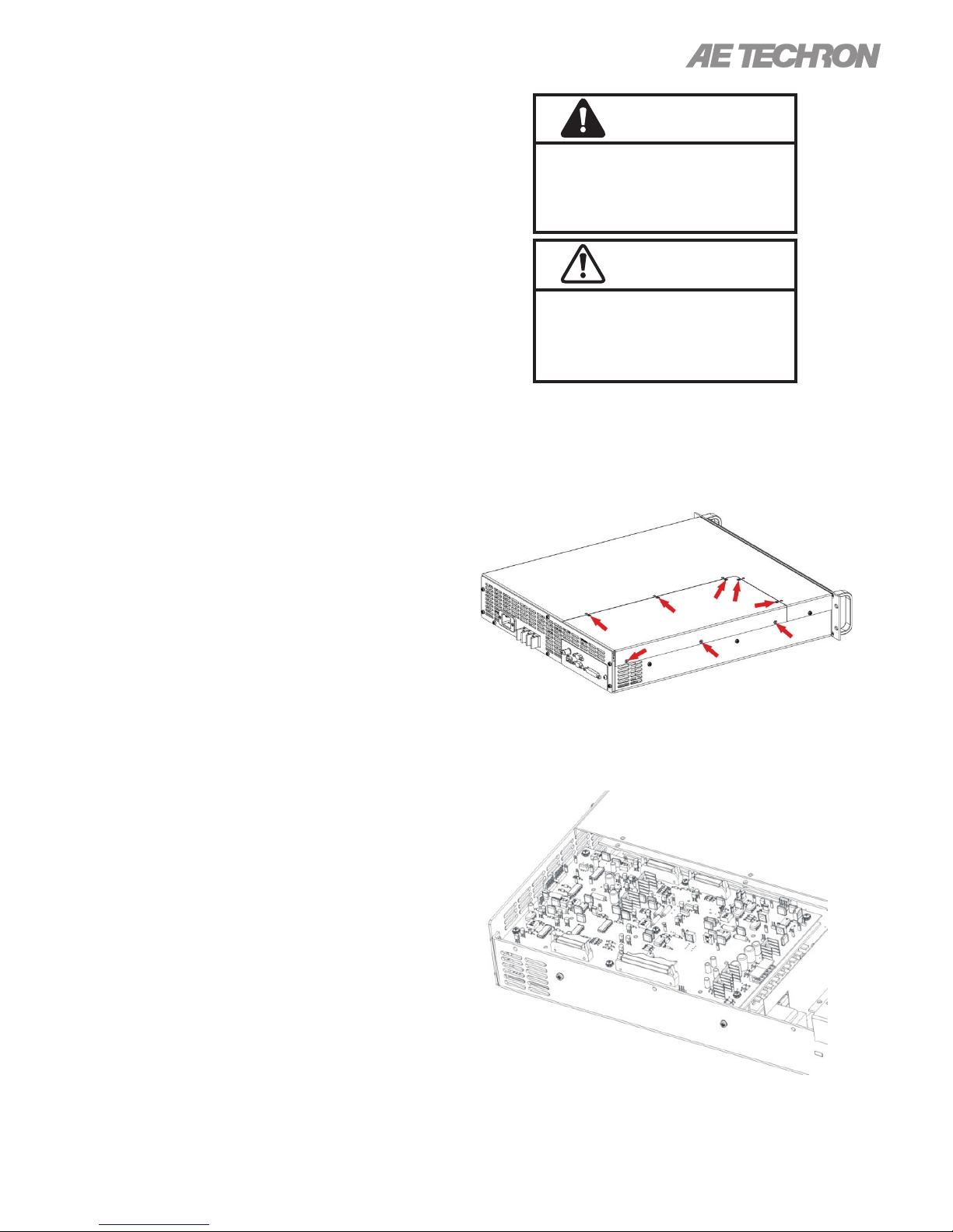
2. Using a #2 Phillips screwdriver (provided), remove the 8 screws located on the top and side
of the amplier.
3. Remove the Access Panel and set it aside.
If you need to make changes to your amplier’s
conguration, please follow the instructions con-
tained in this chapter.
5.1 Conguration Access Panel
The 2105amplier contains an Access Panel built
into the top cover. Most conguration settings
can be made through this Access Panel. For your
convenience, a #2 Phillips screwdriver is provided
in your Toolkit for use in this procedure.
IMPORTANT: Before removing the Access
Panel, make sure the amplier is turned off
for at least 3-5 minutes and the AC mains are
disconnected.
1. Locate the Access Panel as shown in Figure
5.1. Make sure that all 8 screws are acces-
sible. Remove the unit from its rack, if necessary.
Figure 5.1 – Access Panel Screw Locations
Figure 5.2 – Main Board Location Inside
Access Panel
97-2105006_4-2-15
Information subject to change
17
Page 18
5.2 Conguration Settings Located on
the Main Board
The following custom settings can be made via
jumper settings on the Main Board, which is
located inside the Access Panel compartment, as
shown in Figure 5.2.
• Master/Slave setting for stand-alone or multi-
ple-amplifier systems.
• Variable or Fixed Gain setting.
• Controlled Current/Controlled Voltage setting.
5.2.1 Master or Slave Setting
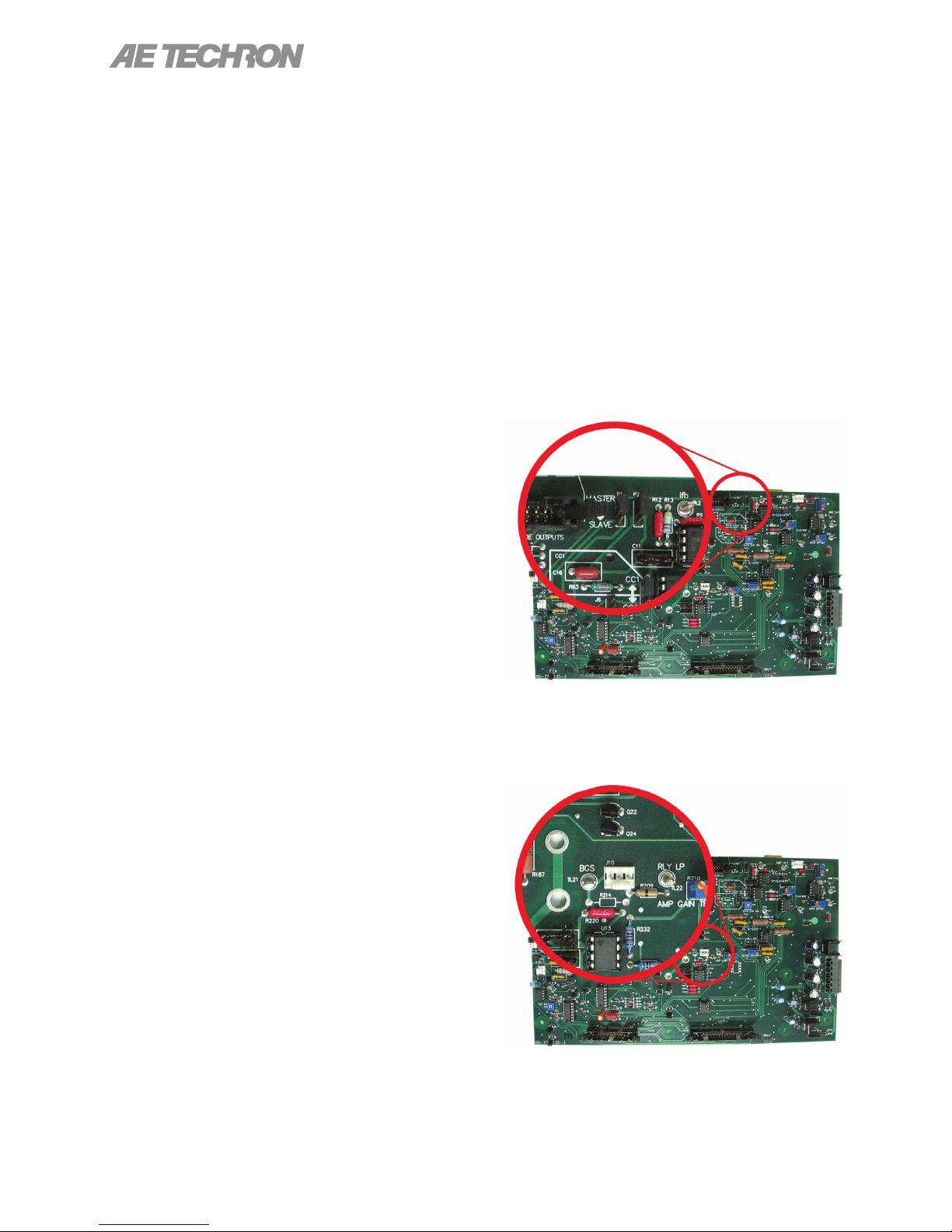
To enable the 2105 amplier for use as a single
amplier or as the Master amplier in a multi-amplier system, set jumpers P1 and P2 in the Master
position (jumpers across top two pins of each set).
To enable the 2105 amplier for use as a Slave
amplier in a multi-amplier system, set jumpers
P1 and P2 in the Slave position (jumpers across
bottom two pins of each set). See Figure 5.3.
2105 OPERATOR’S MANUAL – SECTION 5
• Compensation setting to select RC network
when operating in Controlled Current mode.
• Stop Mode/Run Mode setting for selection of
power-up state.
• Standby mode on Over Temp setting to trigger
Standby mode when amplifier senses an OverTemperature state.
• Standby mode on Over Load setting to trigger
Standby mode when amplifier senses an Over
Load state.
For complete information on multi-amp system
conguration and wiring, please consult the AE
Techron Multi-Amp Conguration Guide available for download from the AE Techron website at
www.aetechron.com.
5.2.2 Fixed Gain/Variable Gain Setting
The 2105 amplier ships with an enabled Gain
Control knob (located on the amplier front panel).
To disable the Variable Gain control and set for a
Fixed Gain of 20, locate and unplug the red con-
nector from jumper J10. Then place a jumper on
the left two pins at that location. See Figure 5.4.
Figure 5.3 – Master/Slave Setting
Figure 5.4 – Gain Trim Control
18
Information subject to change
97-2105006_4-2-15
Page 19
2105 OPERATOR’S MANUAL – SECTION 5
In Controlled-Current Mode, the load is part of the amplier circuit, and the relationship of the
load to the amplier is critical. For proper and safe operation in Controlled-Current mode, you
must obverve the following guidelines:
1. Properly attach a load before operating the amplier. Use only the Output and Sampled
Common terminals. DO NOT use the Common terminal.
2. DO NOT use a blocking capacitor. The load must have a DC path.
3. Never leave the load open. If you feel the load must be fused, which could lead to a poten-
tial open circuit, please contact AE Techron Application Engineering department.
4. Check to make sure the load has some inductive component.
5. Provide appropriate Compensation for the load.
6. Turn of the amplier immediately if oscillation occurs.
Failure to follow these guidelines may result in damage to the amplier
or load.
CAUTION
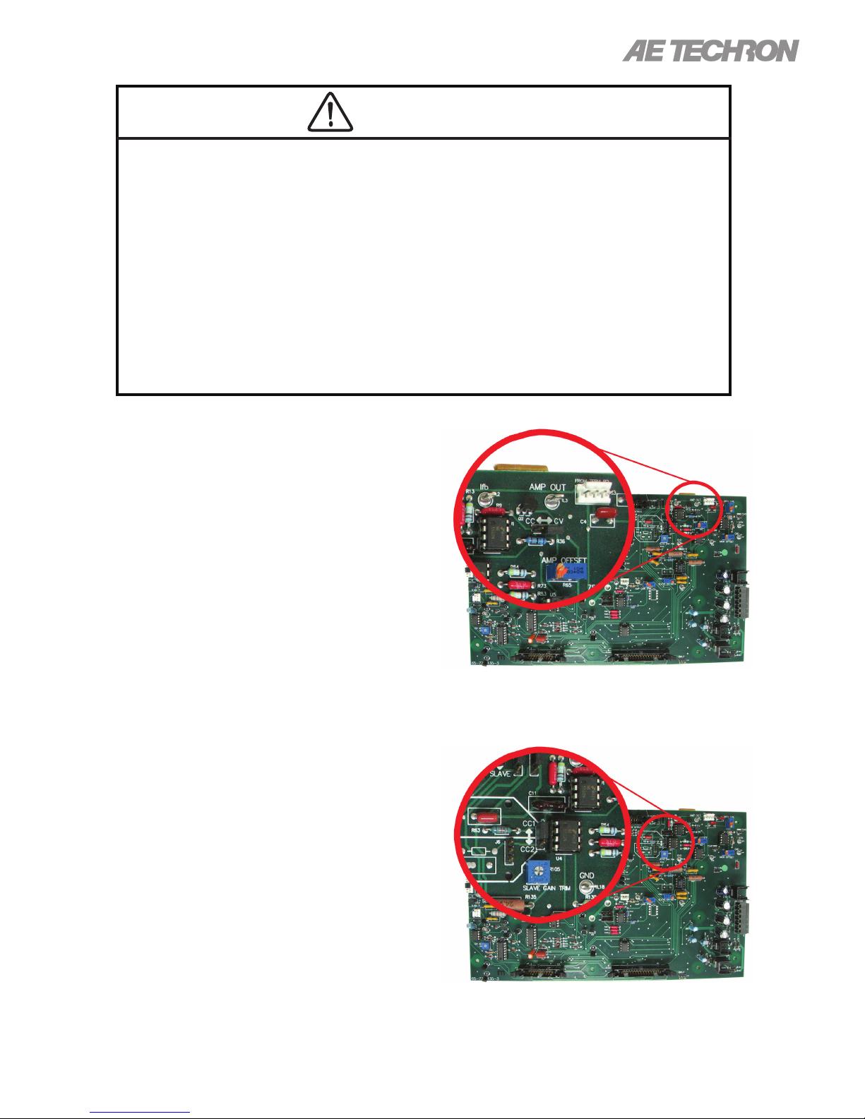
5.2.3 Controlled Voltage or Controlled
Current Setting
To allow the 2105 amplier’s output voltage to be
controlled by its input voltage signal (CV mode),
place Jumper J4 in the RIGHT position (right pair
of pins). To allow the 2105 amplier’s output current to be controlled by its input voltage signal (CC
mode), place Jumper J4 in the LEFT position (left
pair of pins). See Figure 5.5. For more informa-
tion on Controlled-Current operation, see the “Applications” section of this manual.
5.2.4 Compensation Setting (applies
to Controlled Current operation
only)
When the 2105 amplier is used in Controlled Current (CC) mode, the current control loop is tuned
with one of two available RC networks: CC1 (R63
and C16) or CC2 (R82 and C25). Place Jumper
J5 in the UP position to select the CC1 network
(factory default). Place Jumper J5 in the DOWN
position to select the CC2 network. See Figure
5.6. For more information on Controlled-Current
operation, see the “Applications” section of this
manual.
Figure 5.5 – Controlled-Voltage/
Controlled-Current Mode Setting
Figure 5.6 – Compensation Setting
97-2105006_4-2-15
Information subject to change
19
Page 20
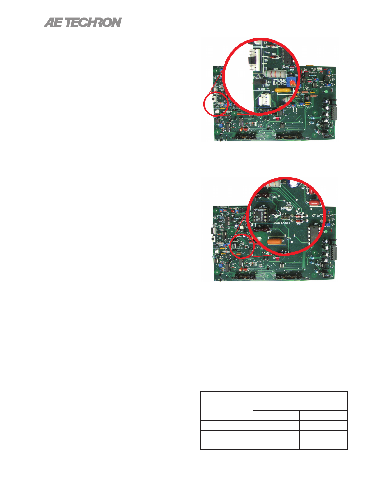
5.2.5 Ready/Run Mode or Standby
Mode Power-up
The 2105 amplier will bypass Standby Mode and
cycle directly to Ready/Run Mode on power-up
when Jumper J11 is in the Left position (factory
default). To set the amplier to power-up to Stand-
by Mode, place Jumper J11 in the Right position.
See Figure 5.7.
5.2.6 Standby Mode on Overload
When enabled, the 2110/2120 amplier will move
into Standby Mode when it senses an activation of
the IOC (Input/Output Comparator) Distortion Alert
circuit. The IOC Distortion Alert circuit continu-
ously compares the input waveform to the output
waveform. When a distortion of more than 0.5%
occurs, the IOC circuit will activate. The ampli-
er will remain in Standby Mode until the Reset
switch on the front panel is pushed or a Reset
signal is received on the Interlock – I/O Connector.
Once reset, the amplier will return to Ready/Run
(operational) Mode. To enable Standby Mode on
Overload, place the jumper across the two pins
labeled J13. See Figure 5.8.
5.3 Conguration Settings Located on
the Power Supply Board
The following custom settings can be made via
plug-in connectors located on the Power Supply
Board:
• Amplifier Voltage Potential setting (high current
or high voltage)
• Bi-Level Power Supply setting
2105 OPERATOR’S MANUAL – SECTION 5
Figure 5.7 – Run Mode/Stop Mode
on Power-Up Setting
Figure 5.8 – Standby Mode on Over Load Setting
5.3.1 Selecting the Best Voltage
Potential and Bi-Level Power
Switch Settings for Your
Application
The output of the amplier will be determined by
the combination of settings used for both Voltage
Potential and Bi-Level Power Switch.
OUTPUT VOLTAGE
Bi-Level
Switch Setting
Auto 45-90 90-180
High 90 180
Low 45 90
Voltage Potential Setting
90 180
20
Information subject to change
97-2105006_4-2-15
Page 21
2105 OPERATOR’S MANUAL – SECTION 5
Use the following general guidelines to select the
best combination of settings to t your requirements:
LOAD
OUTPUT
High
Voltage 16, 8 ohm
Mid-Level 4, 2 ohm 2, 1 ohm
High
Current 1, 0.5 ohm
Also see the “9 Specications” on page
43section for more information.
5.3.2 Accessing the Power Supply
Board
To access the Power Supply Board, follow the in-
structions given at the beginning of this Section to
open the Conguration Access Panel. The Power
Supply Board is located to the right of the Main
Board, as shown in Figure 5.9.
16, 8, 4
ohm
0.75 - 0.25
ohm
SettingsContinuous Pulse
180 V
Auto
90 V
Auto
90 V
Low
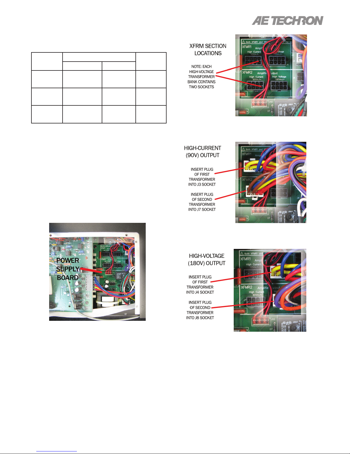
Figure 5.10 – Location of Amplier High-Voltage
Transformer Sockets
Figure 5.9 – Accessing the Power Supply Board
5.3.3 Changing Amplier Voltage
Potential
The 2105 can be congured for High Current (90V)
or High Voltage (180V) operation via userselectable plugs on the Power Supply Board.
Complete the following steps to change the amplier voltage potential.
Figure 5.11 – J3 and J7 Plug Locations for
High-Current Output
Figure 5.12 – J4 and J8 Plug Locations for
High-Voltage Output
1. Locate the two XFMR sections (left of Line
Voltage sections) (see Figure 5.10).
2. For High Current (90V) Output (see Figure
5.11).
3. For High Voltage (180V) Output (see Figure
5.12).
97-2105006_4-2-15
Information subject to change
21
Page 22
5.3.4 Changing Bi-Level Power Supply
Function
The 2105offers three Bi-Level switch settings:
Automatic, High, or Low. The user can select
between settings via a switch on the Power Supply
Board.
To access and change the Bi-Level Power Switch,
follow these steps:
1. Locate the SIM Input Card on the right side of
the rear panel of the amplier.
2. Using a #2 Phillips screwdriver (provided),
remove the 2 screws located at the edges of
the SIM card.
3. Keeping the ribbon cable attached, remove the
SIM card from the amplier until it is completely
clear from the card bay.
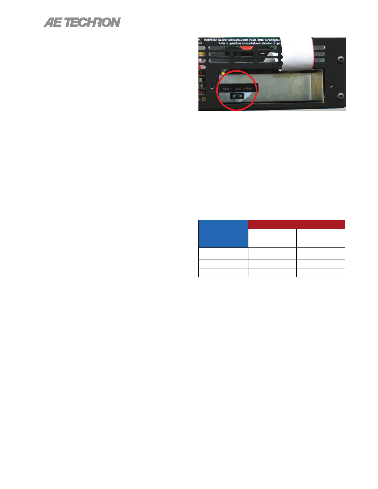
4. Locate Bi-Level Power Switch, S1, a black,
three-position switch at the rear of the card
bay.(See Figure 5.13)
5. Move the Black switch to desired setting. If
necessary, use a pointed, non-metallic object
(such as a pen) to help in moving the switch.
a. Automatic – Left
b. Low – Middle
2105 OPERATOR’S MANUAL – SECTION 5
Figure 5.13 – Bi-Level Power Switch Location
5.3.5 Selecting the Best Voltage Potential and Bi-Level Power Switch
Settings for Your Application
The output of the amplier will be determined by
the combination of settings used for both Voltage
Potential and Bi-Level Power Switch.
OUTPUT VOLTAGE
BI-LEVEL
SWITCH
SETTING
AUTO 45 - 90 90 - 180
HIGH 90 180
LOW 45 90
VOLTAGE POTENTIAL SETTING
High Current
(90V)
High Voltage
(180V)
c. High – Right
22
Also see the “Specications” section for more
information.
Information subject to change
97-2105006_4-2-15
Page 23
2105 OPERATOR’S MANUAL – SECTION 6
6 Applications
6.1 Controlled Current Operation
The procedures outlined in this section assume
competence on the part of the reader in terms of
amplier systems, electronic components, and
good electronic safety and working practices.
6.1.1 Controlled-Voltage vs.
Controlled-Current Modes
of Operation
AE Techron 2105 ampliers can be eldcongured to operate as Voltage Ampliers
(Voltage-Controlled Voltage Source) or as Trans-
conductance Ampliers (Voltage-Controlled
Current Source). The mode selection is made via a
jumper setting located on the amplier main board.
See the ”Advanced Conguration” section for
more information.
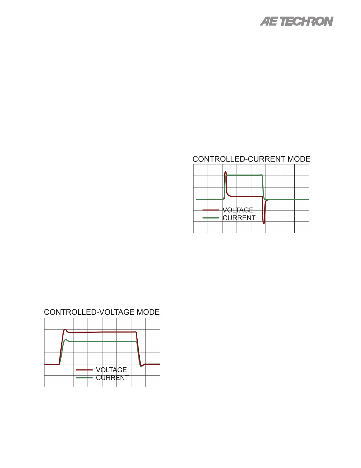
Conversely, when congured as a ControlledCurrent source (transconductance amplier), the
amplier will provide an output current that is constant and proportional to the control (input) voltage. If the load’s impedance changes, the amplier
will seek to maintain this transconductance (ratio
of input voltage to output current) by increasing or
decreasing the voltage it produces, as long as it is
within the amplier’s ability to create the required
voltage. Use this mode if you want the output current waveform to be like the input waveform (see
Figure 6.2).
When congured as a Controlled-Voltage source
(voltage amplier), the amplier will provide an
output voltage that is constant and proportional
to the control (input) voltage. If the load’s impedance changes, the amplier will seek to maintain
this ratio of input to output voltage by increasing or
decreasing the current it produces, as long as it is
within the amplier’s ability to create the required
current. Use this mode if you want the output voltage waveform to be like the input waveform (see
Figure 6.1).
Figure 6.1 – Input to Output Comparison,
Controlled-Voltage Operation
Figure 6.2 – Input to Output Comparison,
Controlled-Current Operation
6.1.2 Safety and Operation Considerations for Controlled Current
Operation
When an AE Techron amplier is congured as
a Controlled Current source, care needs to be
exercised in its operation. Any voltage controlled
current source should never be turned on
without a load, (with some impedance, real or
effective) connected to its output terminals.
When asked to operate in this way, any current
source (including an AE Techron amplier) will increase its output voltage in an attempt to drive the
requested current into the load. In an open-circuit
condition, creating current ow will be impossible.
The current source will increase its output voltage
until it reaches its voltage limit. This is a potentially
dangerous condition for both the AE Techron amplier and for any user who might come in contact
with the amplier output terminals.
97-2105006_4-2-15
Information subject to change
23
Page 24
2105 OPERATOR’S MANUAL – SECTION 6
When operating in Controlled Current (CC) mode,
a compensation circuit is required to ensure ac-
curate output current. Since the load is a critical
circuit component in CC mode, the inductive and
resistive values of the load will determine the
required compensation values. While the factorydefault compensation setting will be sufcient
for some applications, the compensation setting
may also be adjusted in the eld. The following
section describes methods for determining and
setting proper compensation when operating in
Controlled-Current mode.
6.1.3 Controlling Compensation for
CC Operation
AE Techron 2105 ampliers can be congured for
either Controlled Voltage (CV) or Controlled Current (CC) mode of operation. When operating the
amplier in Controlled Voltage (CV) mode, compensation is not required. However, when operating in Controlled Current (CC) mode, the amplier
load becomes an integral part of the system. In
order to ensure system stability and to control
available bandwidth, compensation via an RC
network is required for CC operation. The following
steps will allow you to compensate your amplier
for operation in CC mode safely and effectively.
STEP 1: Check Amplier Operation in
CV mode.
We recommend that you power-up and enable the
amplier in Controlled Voltage mode without attaching a load before conguring your amplier for
Controlled Current operation. This will allow you
to verify that the input signal and the amplier are
operating correctly.
Once this initial check is completed, power down
the amplier and access the amplier main board
to place the amplier in CC mode. (Refer to the
“Advanced Conguration” section for more infor-
mation.)
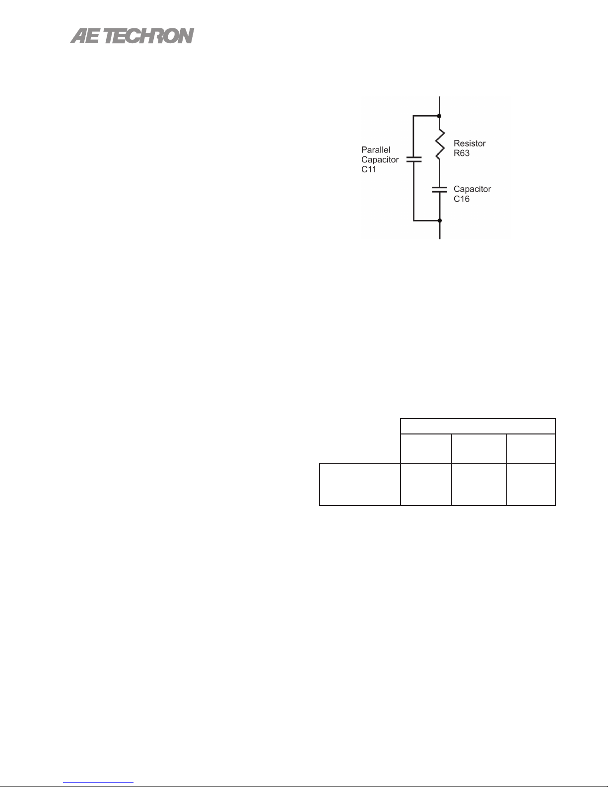
One of two compensation settings can be selected
via jumpers on the main board: CC1 which en-
ables the factory-installed RC network (see Figure
6.3), or CC2 which allows installation of a custom
RC network.
Figure 6.3 – Factory-installed Default RC Network
STEP 2: Determine Required
Compensation.
When operating an amplier in Controlled Current mode, the load becomes an integral part of
the system. In order to determine the required
compensation for your load, begin by consulting
the following table to determine the approximate
compensation capacitance (C) required based on
the inductance of your load:
Load Inductance (L)
<200 µH
Compensation
Capacitance
(CC)
NOTE: Load Resistance (R) is assumed to be
<5 ohms.
STEP 3: Determine if Default or Custom
Compensation is Required.
If your load inductance is between 200 microHenries and 1 milliHenry, and your load resistance
is less than 5 ohms, then you can likely use the
default compensation provided by the amplier’s
factory-installed RC network. To select the factorydefault compensation, please see STEP 4 to
follow.
0.001 µF 0.01 µF 0.1 µF
<>200 µH
to <1 mH
>1 mH
24
Information subject to change
97-2105006_4-2-15
Page 25

2105 OPERATOR’S MANUAL – SECTION 6
If your load inductance falls outside of the mid-
range, or if your load resistance is greater than
5 ohms, then you must calculate your required
compensation. If, after calculating your required
compensation, you determine that the default com-
pensation will be insufcient for your load, then
you will need to enable and install a custom RC
network. See STEP 6 below.
STEP 4: Enabling Your Compensation
Setting.
AE Techron 2100 Series ampliers can be enabled
with one of two compensation settings: default
RC network or custom RC network. The required
network can be selected via jumpers on the main
board. CC1 enables the default (factory-installed)
RC network, while CC2 allows installation of a custom RC network. Figure 6.3 describes the default
RC circuit.
To select CC1, place jumper J5 in the UP position; to select CC2, place jumper J5 in the DOWN
position. (For jumper location, see the ”Advanced
Conguration” section.)
IMPORTANT: If CC2 is selected, you must calculate the compensation requirements for your
custom RC network and install the network on
your amplier main board before operating the
amplier in CC mode.
STEP 6: Installing an RC Network for
Custom Compensation
If the default RC network does not provide suitable compensation for your intended load, you
will need to install a custom RC network that is
matched to your load. This network will require two
components (a resistor (R) and a capacitor (C))
to be installed on the main board. To calculate the
approximate values required for each component,
use the following formulas.
COMPENSATION FORMULAS:
To nd the value for the resistor (Rc) in the RC
network:
Rc = 20,000 x 3.14 x L x BW
where:
Rc is compensation resistance in ohms.
L is load inductance in henries.
BW is bandwidth in hertz.
To nd the value for the capacitor (Cc) in the
RC network:
Cc = L/ (R x Rc)
where:
Cc is compensation capacitance in farads.
L is load inductance in henries.
R is resistance of load in ohms.
STEP 5: (Optional) Verify Suitability of
Default Compensation (CC1)
If desired, the following values of the components
contained in the default RC network can be used
with the formulas provided in STEP 6 below to
verify the suitability of the default compensation for
your uses.
Pins Jumped: 1 and 2 (UP)
Compensation Resistor: R63 (68 Kohms)
Compensation Capacitor: C16 (0.047 µF)
Parallel Capacitor: C11 (47 pF)
97-2105006_4-2-15
Rc is compensation resistance in ohms.
STEP 7: Optimizing the Compensation
Values.
Once an approximate Rc and Cc have been
computed, these values will need to be evaluated.
To do this, install components with the required
values in the main board at locations R82 and C25
as shown in Figure 6.4.
Remember the load you are connecting is a
part of the system and the amplier should not
be turned on without the load being connected.
After installing the components, check to ensure
that jumper J5 is correctly installed (see STEP 4),
then power up the amplier without signal input.
Information subject to change
25
Page 26
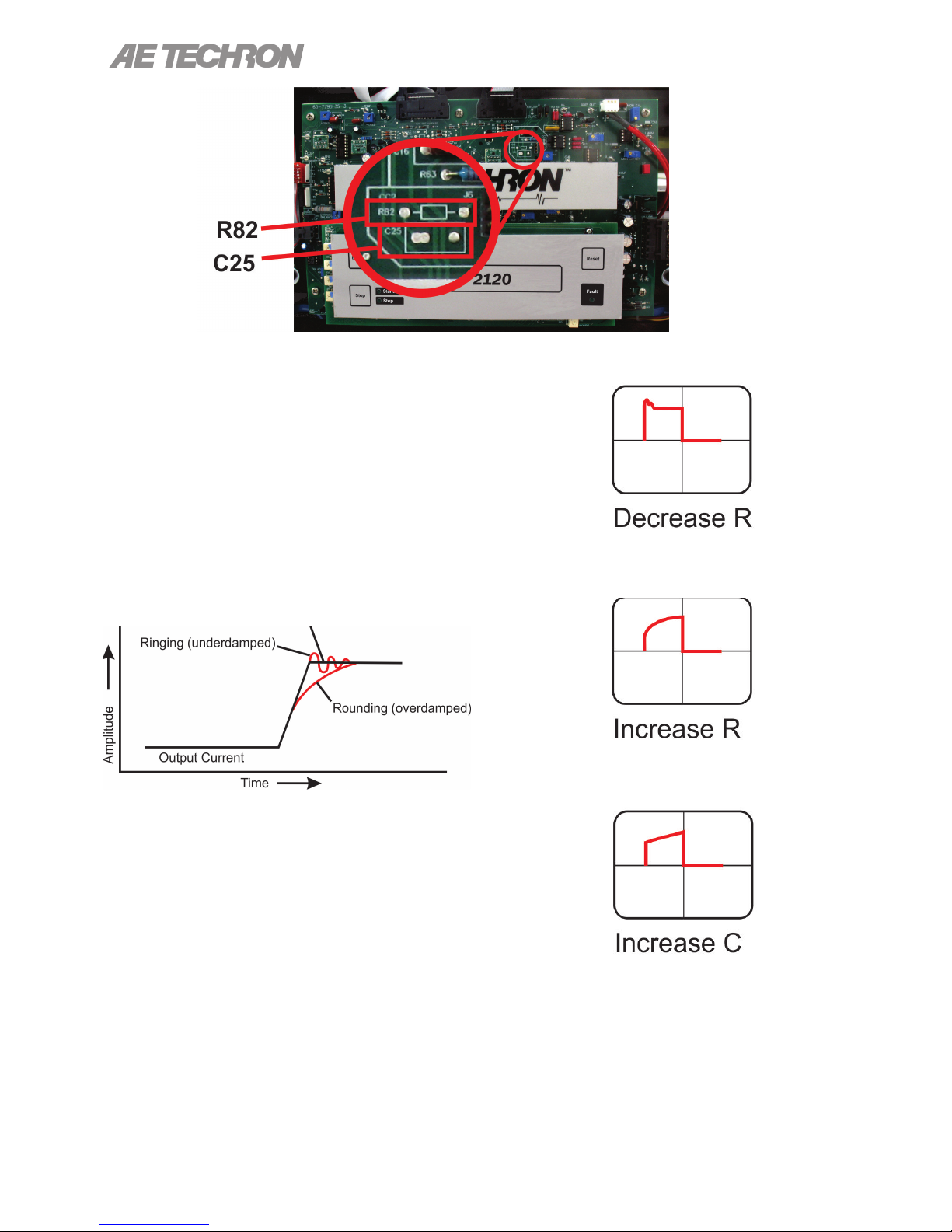
Figure 6.4 – Custom Compensation Location
To begin testing, input a square wave with a frequency of 100 Hz to 1 kHz, or a squared pulse at a
low level (typically 0.25 to 2.0 volts). A limited-rise-
time, repetitive pulse of low duty cycle is preferred.
Observe the output current through a current
monitor or current probe. Look for clean transition
edges. The presence of ringing or rounding on the
transition edges indicates compensation problems.
(See Figure 6.5.)
2105 OPERATOR’S MANUAL – SECTION 6
Figure 6.6 – Square Wave Showing a
Decrease in R is Required
Figure 6.5 – Compensation Effects on Waveform
If a change in compensation is necessary, an ad-
justment to the resistor component of the Compen-
sation circuit is probably required.
If the output current waveform is ringing, the circuit
is underdamped: You have too much gain and
should lower the resistance (see Figure 6.6).
If the output current waveform is rounded, the
circuit is overdamped: You have too little gain and
should increase resistance (see Figure 6.7).
26
Figure 6.7 – Square Wave Showing an
Figure 6.8 – Square Wave Showing an
If the output current waveform is neither underdamped or overdamped, but the top of the squarewave is not level, then you should instead increase
the capacitor value (see Figure 6.8).
Information subject to change
Increase in R is Required
Increase in C is Required
97-2105006_4-2-15
Page 27
2105 OPERATOR’S MANUAL – SECTION 6
When making adjustments:
Resistor: Increase or decrease resistance values
in increments of +/- 10%.
Capacitor: Incrementally increase capacitor values by a factor of 2 or 3.
After nal adjustments have been made to the
circuit, the nal waveform for your planned application should be tested to conrm the amplier’s
compensation setting.
6.2 Remote Status and Control using
the SIM Interlock I/O Connector
The procedures outlined in this section assume
competence on the part of the reader in terms of
amplier systems, electronic components, and
good electronic safety and working practices.
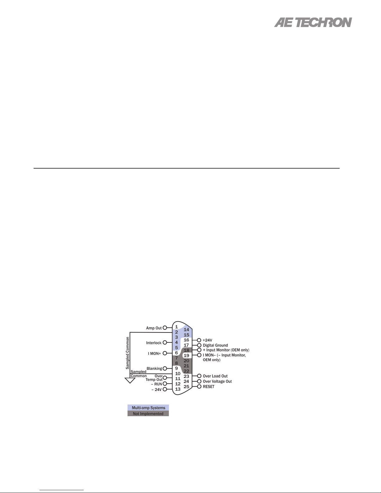
AE Techron 2105 ampliers come with a SIM-BNC
input module that also contains a female, 25-pin
D-Sub connector. This connector can be used
to provide remote control and monitoring of the
amplier.
The information provided here will instruct you in
the wiring of several control and status applications including:
NOTE:
• If possible, use 1% metal film resistors. AE
Techron discourages installation of potentiome-
ters in the resistor location of the compensation
circuit because this can decrease stability and
may increase inductance.
• The parallel capacitor in the RC network serves
to increase stability but can be removed, if it is
not required for system stability. If the parallel
capacitor is used, it will usually decrease the
value of resistance needed.
• In multiple amplifier systems, expect to decrease
the value of R63 in series systems by 1/2.
• Remote Run / Standby
• Over-temperature status
• Run status
• Overload status
• Overvoltage status
• Reset after Over-temperature or Overload error
• Current monitor
Figure 6.9 maps the pins used for these applications.
For a detailed chart of all DB-25 pinouts,
see ”Appendix 1.”
.
Figure 6.9 – Remote Status and Control Pinouts
97-2105006_4-2-15
Information subject to change
27
Page 28
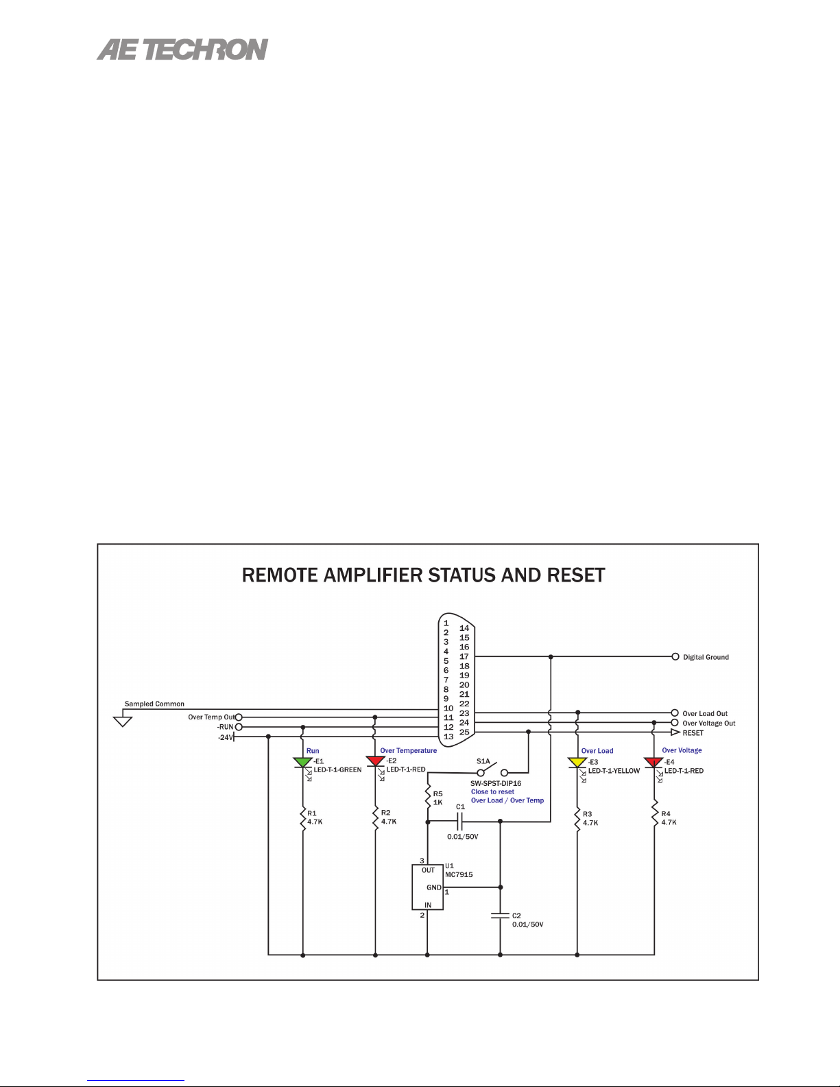
2105 OPERATOR’S MANUAL – SECTION 6
6.2.1 Remote Amplier Status and
Reset
The SIM Interlock I/O Connector can be used to
create a circuit to monitor remotely one or more
amplier conditions, including Run status, Overtemperature, Overload and Overvoltage. The cir-
cuit can also be constructed to allow remote reset
of the amplier when it is forced to Standby due to
Over-temperature or Overload conditions.
Use a male, 25-pin D-Sub connector and highquality wire to build the circuit. Figure 6.10 sche-
matic details the circuit and components required
for all status and reset functions.
Remote Signal of Over Temperature
Condition
Purpose: LED, when lit, signals Over Temperature
condition.
Method: Use a 6mA series resistor of 4.02 Kohm
for LED or OPTO, tie OverTemp Out (PIN 11) to
-24V source (PIN 13).
Signal Type: DC
Level when Asserted: –24V
Level when Deasserted: 0V
Note: When amp is normal, this pin is pulled to
–24V through a 47.5K-ohm resistor; when amp
is in Overtemp state, transistor Q37 turns on and
sources chassis ground as an output. Do not exceed 20 milliamps.
An Overtemp condition will force the amp to
Standby. The amplier will automatically move to
Run when temperature cools to operating levels.
Remote Signal of Run Condition
Purpose: LED, when lit, signals Run state.
Method: Use a 6mA series resistor of 4.02K-ohm
for LED or OPTO, tie Run (PIN 12) to –24V source
(PIN 13).
Signal Type: DC
Level when Asserted: –24V
Level when Deasserted: 0V
Remote Signal of Overload Condition
Purpose:
Method: Use a 6mA series resistor of 4.02K-ohm
for LED or OPTO, tie OverLoad Out (PIN 23) to
–24V source (PIN 13).
Signal Type: DC
Level when Asserted: –24V
LED, when lit, signals Overload condition.
Figure 6.10 – Remote Status and Reset Schematic
28
Information subject to change
97-2105006_4-2-15
Page 29
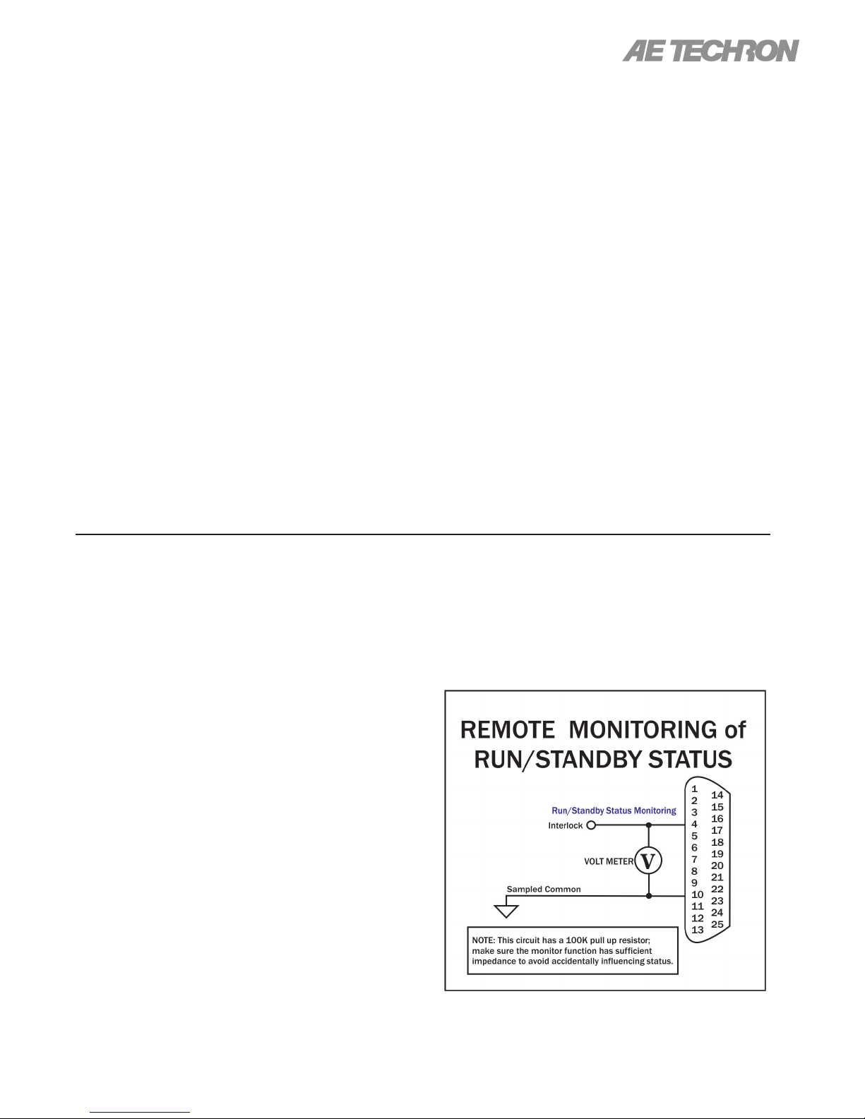
2105 OPERATOR’S MANUAL – SECTION 6
Level when Deasserted: 0V
Note: When amp is normal, this pin is pulled to
–24V through a 47.5K-ohm resistor; when amp
is in Overload state, transistor Q36 turns on and
sources chassis ground as an output. Do not exceed 20 milliamps.
An Overload condition will not place the amplier
in Standby when operating with the factory default settings. In order to clear the fault condition,
reduce the input levels until the Fault LED turns
off. However, if the Standby Mode on Overload
option is set, an Overload condition will force amp
to Standby. To return the amplier to Run mode,
reduce the input signal level, then trigger a Reset
command using the front-panel Reset button or a
remote amplier Reset command.
Remote Signal of OverVoltage Condition
Purpose:
Method: Use a 6mA series resistor of 4.02K-ohm
for LED or OPTO, tie OverVoltage Out (PIN 24) to
–24V source (PIN 13).
Signal Type: DC
Level when Asserted: –24V
LED, when lit, signals Overvoltage condition.
Level when Deasserted: 0V
Note: When amp is normal, this pin is pulled to
–24V through a 47.5K-ohm resistor; when amp
is in Overvoltage state, transistor Q29 turns on
and sources chassis ground as an output. Do not
exceed 20 milliamps.
Reset from Standby
Purpose: Switch, when thrown, returns amp to
Run condition after Over-temperature or Overload
conditions.
Method: Use a dry-contact switch, voltage regulator (MC7915), and two 0.01/50V capacitors; wire
the circuit as shown (above). Assert 15V for at
least 100 ms to clear the error condition.
Signal Type: DC
Level when Asserted: –15V
Level when Deasserted: 0V
Note: Tie to PIN 13 (–24V dc) and create a –15V
dc source; <2mA required for reset. Connect the
–15V dc source to PIN 25 (Reset) through a 1K
buffer resistor to reset.
6.2.2 Remote Run/Standby Status
Monitor
Using the SIM-BNC Interlock connector located on
the back panel of the amplier, you can remotely
monitor the Run/Standby status of the amplier.
Remote Run/Standby Status
Purpose: Use a voltage meter to monitor the status of the amplier to determine if the amplier is in
a “Run” or “Standby” state.
Method: Connect a voltage meter to monitor the
circuit voltage. Connect across PIN 4 (Interlock)
and PIN 10 (Sampled Common).
When the voltage meter reads greater than 10V,
the amplier is in the Run state; when the meter
reads less than 10V, the amplier is in the Standby
state. See Figure 6.11.
Signal Type: DC
Level when Asserted: >10 V
Level when Deasserted: <10 V
IMPORTANT: This circuit has a 100K pull-up resistor. Make sure the monitor function has sufcient
impedance to avoid accidentally inuencing status
97-2105006_4-2-15
Figure 6.11 – Remote Run/Standby Monitor
Information subject to change
29
Page 30
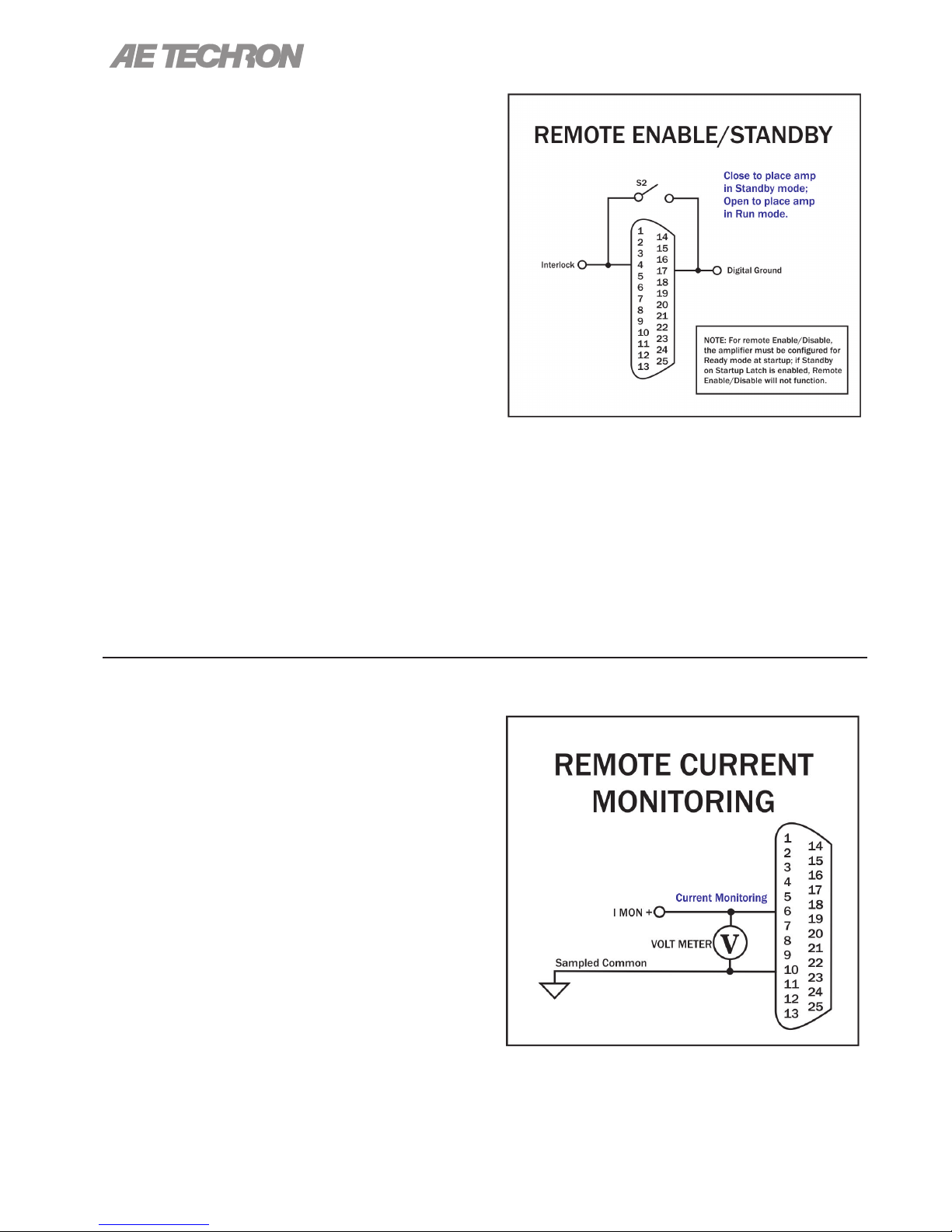
6.2.3 Remote Enable/Standby
Using the SIM-BNC Interlock connector located
on the back panel of the amplier, you can remotely Enable the amplier and/or place the unit in
Standby mode. See Figure 6.12.
Remote Enable/Standby
Purpose: Use a switch or optocoupler to remotely
disable the amplier and place it in Standby mode.
Also, return the amplier from Standby mode to
the Run condition.
Method: Short PIN 4 of amplier to Digital Ground
(PIN 17) using a dry contact switch or optocoupler.
In multi-amp applications, a switch can be used for
Parallel systems, but an optocoupler must be used
for Series systems. Multiple ampliers (sharing the
same Sampled Common power connections) can
be simultaneously forced to Standby by daisy-
chaining Interlock (PIN 4) across amps.
When Interlock (PIN 4) is shorted to Digital Ground
(PIN 17), the amplier is placed in Standby mode.
When switch is open, the amplier is released to
the Run condition.
Signal Type: DC
Level when Asserted: 0 to 8 V
Level when Deasserted: 10 to 15 V
2105 OPERATOR’S MANUAL – SECTION 6
Figure 6.12 – Remote Enable/Standby
IMPORTANT: The amplier must be congured for
Ready mode at startup (factory default) or the Run
button must be pressed at the amplier front panel
at startup. The Remote Enable/Standby circuit will
not function if the Startup to Standby Latch has
been activated on the amplier.
6.2.4 Remote Monitoring of Current
Using the SIM-BNC Interlock connector located on
the back panel of the amplier, you can remotely
monitor both voltage and current output.
Use a male, 25-pin D-Sub connector and highquality wire to build the desired circuits.
Remote Monitoring of Current Output
Purpose: Use a voltage meter to monitor output
current.
Method: Connect a voltage meter to monitor
the output current being produced by the amplier. Connect across PIN 6 (I MON+) and PIN 10
(Sampled Common). See Figure 6.13.
Signal Type: DC
Level when Asserted: 2105: 5A/V; 2110/2120:
20A/V
Level when Deasserted: 0V
Figure 6.13 – Remote Current Monitoring
30
Information subject to change
97-2105006_4-2-15
Page 31
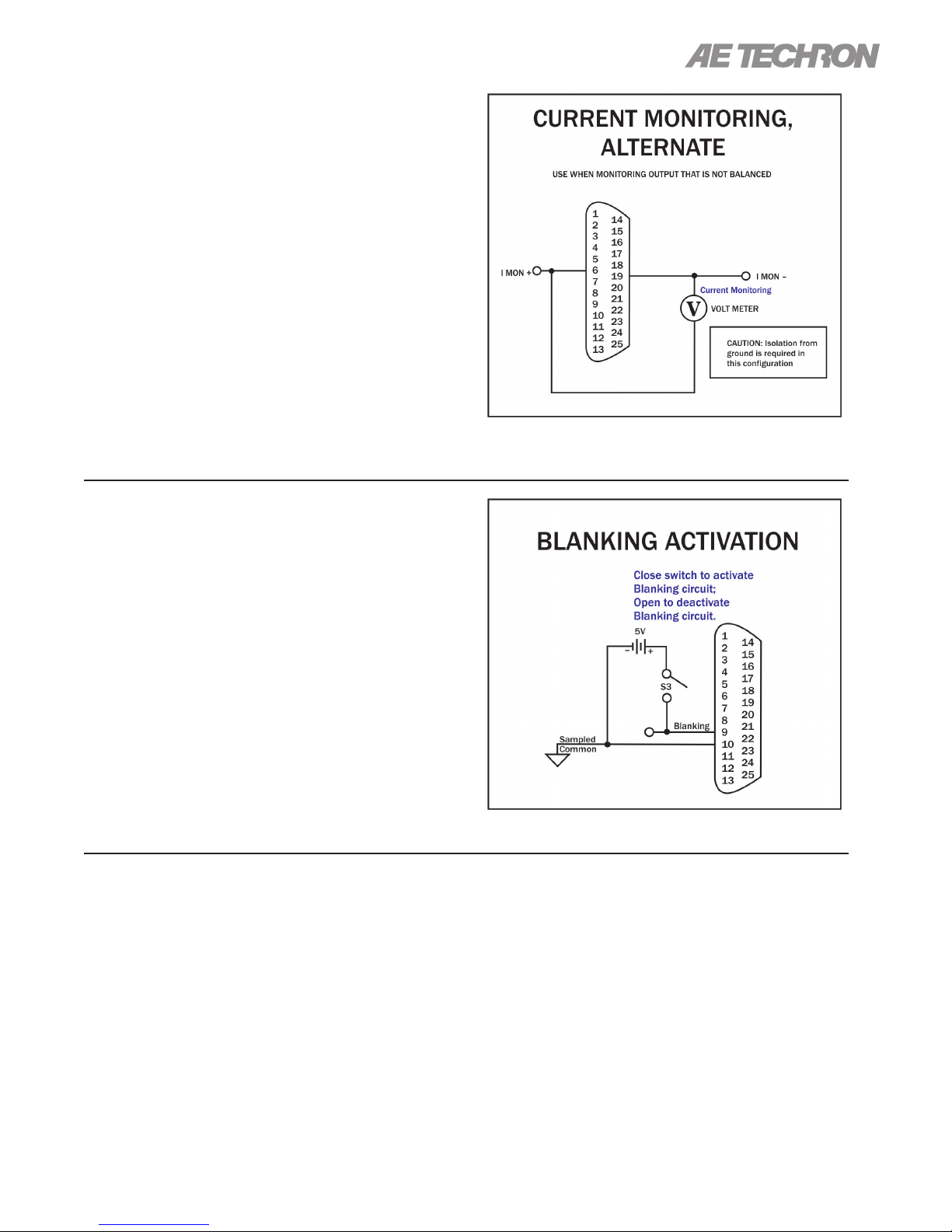
2105 OPERATOR’S MANUAL – SECTION 6
Remote Monitoring of Current Output -
Alternate Method
Purpose: Use a voltage meter to monitor output
current when output is not balanced.
Method: Connect a voltage meter to monitor
the output current being produced by the amplier. Connect across PIN 6 (IMON+) and PIN 19
(IMON-). See Figure 6.14.
Signal Type: AC
Level when Asserted: 2105: 2.5A/V; 2110/2120:
10A/V
Level when Deasserted: 0V
CAUTION: To avoid ground loops, isolation from
ground must be provided. Use of a differential
probe is recommended.
Figure 6.14 – Remote Current Monitoring,
Alternate Method
Blanking Circuit Activation
Purpose: Activate the blanking circuit that shuts
down the amplier output stage in less than 10 µs.
Method: Build a switchable circuit using an external, isolated 5V power supply that can apply a +5V
signal to PIN 9. Connect across PIN 9 (Blanking)
and PIN 10 (Sampled Common). See Figure 6.15.
Signal Type: DC
Level when Asserted: 3-5 Vdc
Level when Deasserted: 0-1 Vdc
6.3 Multi-amplier Systems
The 2105 amplier may be used with other samemodel ampliers to increase voltage or current.
Because the internal circuitry of a 2105 amplier
is not connected to chassis ground, the amplier
is well suited for use in series or parallel with other
ampliers of the same model.
Figure 6.15 – Blanking Activation
contact AE Techron Application Support for infor-
mation on these more complex multi-amp systems.
For routine, controlled-voltage applications ,
Series or Parallel amplier systems can be congured using the following accessories available from
AE Techron:
Up to three 2105 ampliers may be congured in
series, and up to four may be congured in parallel. Congurations with more ampliers may be
possible, depending on the application. Please
97-2105006_4-2-15
SIM-OPTOC – The SIM-BNC-OPTOC Specialized
Input Module allows multiple 2100-Series ampli-
ers to be congured as a series output system to
increase the available output voltage to the load.
Information subject to change
31
Page 32

2105 OPERATOR’S MANUAL – SECTION 6
The SIM-BNC-OPTOC kit also includes a BNC
connector safety cover.
The SIM-BNC-OPTOC module is required for all
Series congurations and should be used in conjunction with the DB9M CABLE (see below).
DB9M CABLE – The DB9M (OPTOC) CABLE is a
high-voltage Interlock cable that provides superior
insulation for multi-amp series systems running
high-voltage applications.
The DB9M CABLE is required for all Series congurations and should be used in conjunction with
the SIM-BNC-OPTOC module (see above)
BAL RES KIT – Three types available: 2105 BAL
RES KIT, 2110 BAL RES KIT and 2120 BAL RES
KIT. Ballast resistors are required for all Parallel
congurations. The ballast resistor kits include one
ballast resistor (two in the 2120 kit) with connection terminals and mounting hardware. The 2105
BAL RES KIT also contains the shunt required to
defeat the amplier’s external level control.
PARALLEL WIRING KITS – Six types available:
2105 2-AMP, 2110/2120 2-AMP, 2105 3-AMP,
2110/2120 3-AMP, 2105 4-AMP, and 2110/2120
4-AMP. Parallel wiring kits include the DB-25
Interlock cable for system communication, BNC
T-connectors and BNC patch cables for wiring
parallel inputs through the BNC input connectors,
and the output wiring for connecting system ampliers to the load. The kits also include the wire(s)
needed for wiring the parallel inputs through the
Removable Barrier Block (WECO) connectors and
the input terminators required during system setup.
Parallel wiring kits are recommended for all Parallel congurations.
To download the AE Techron Multi-Amp Conguration Guide or for additional information, visit the
AE Techron website at www.aetechron.com.
6.3.1 Accessory Recommendations by System Type
Series Systems
2105, Two in Series:
(2) SIM-BNC-OPTOC input cards,
(1) DB9M OPTOC cable
2105, Three in Series:
(3) SIM-BNC-OPTOC input cards,
(2) DB9M OPTOC cables
6.3.2 Multi-Amp System Output
Capabilities (see following
pages)
Note: Performance levels typical up to 20 kHz fre-
Parallel Systems
2105 Two in Parallel:
(2) 2105 BAL RES kits,
(1) 21050 2-AMP Parallel Wiring kit
2105 Three in Parallel:
(3) 2105 BAL RES kits,
(1) 2105 3-AMP Parallel Wiring kit
2105 Four in Parallel:
(4) 2105 BAL RES kits,
(1) 2105 4-AMP Parallel Wiring kit
quency levels. Above 20 kHz, slew rate may affect
performance, reducing maximum voltage, current
and power output.
32
*Indicates no testing performed.
Information subject to change
97-2105006_4-2-15
Page 33
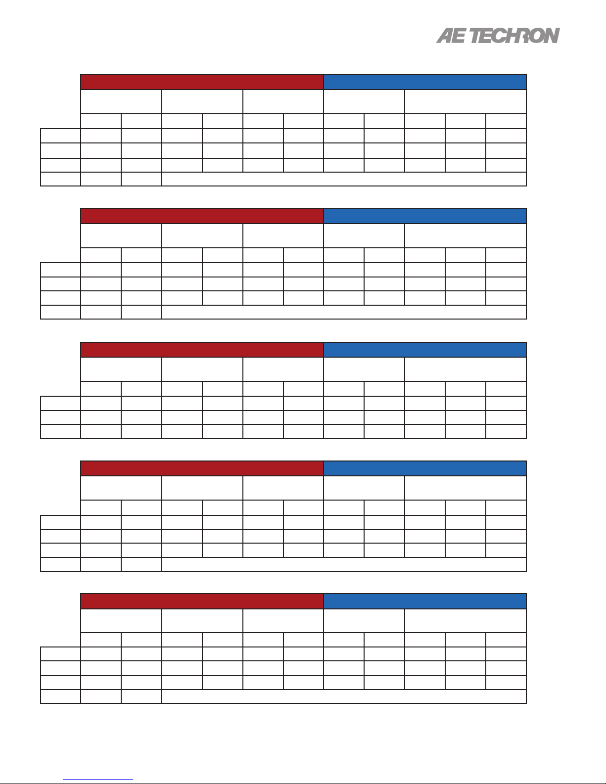
2105 OPERATOR’S MANUAL – SECTION 6
Two 2105s in Series – High-Voltage Mode
PEAK OUTPUT RMS OUTPUT
40 mSec Pulse,
20% Duty Cycle
Ohms Volts Amps Volts Amps Volts Amps Volts Amps Volts Amps Watts
32 316 9.8 316 9.8 316 9.8 223 6.9 223 6.9 1539
16 308 19 272 16.3 272 16.3 192 11.5 192 11.5 2208
8 248 31 216 25.7 122 14.5 153 18.2 86 10.3 886
4 196 49
5 Minutes,
100% Duty Cycle
1 Hour,
100% Duty Cycle
5 Minutes,
100% Duty Cycle
1 Hour,
100% Duty Cycle
Two 2105s in Series – Mid-Level Mode
PEAK OUTPUT RMS OUTPUT
40 mSec Pulse,
20% Duty Cycle
Ohms Volts Amps Volts Amps Volts Amps Volts Amps Volts Amps Watts
8 144 18 138 16.4 138 16.4 98 11.6 98 11.6 1137
4 122 30 114 26.2 114 26.2 81 18.5 81 18.5 1499
2 94 47 86 39.6 42 21 61 28 30 14.8 444
1 52 52
5 Minutes,
100% Duty Cycle
1 Hour,
100% Duty Cycle
5 Minutes,
100% Duty Cycle
1 Hour,
100% Duty Cycle
Two 2105s in Series – High-Current Mode
PEAK OUTPUT RMS OUTPUT
40 mSec Pulse,
20% Duty Cycle
Ohms Volts Amps Volts Amps Volts Amps Volts Amps Volts Amps Watts
2 * * 58 29 58 29 41 20.5 41 20.5 841
1.5 * * 52 34 52 34 37 24 37 24 888
1 * * 46 45 46 45 33 31.8 33 31.8 1049
5 Minutes,
100% Duty Cycle
1 Hour,
100% Duty Cycle
5 Minutes,
100% Duty Cycle
1 Hour,
100% Duty Cycle
Three 2105s in Series – High-Voltage Mode
PEAK OUTPUT RMS OUTPUT
40 mSec Pulse,
20% Duty Cycle
Ohms Volts Amps Volts Amps Volts Amps Volts Amps Volts Amps Watts
48 474 9.8 474 9.8 474 9.8 335 6.9 335 6.9 2312
24 462 16.3 408 16.3 408 16.3 288 11.5 288 11.5 3312
12 372 31 324 25.7 183 14.5 229 18.2 129 10.3 1322
6 294 49
5 Minutes,
100% Duty Cycle
1 Hour,
100% Duty Cycle
5 Minutes,
100% Duty Cycle
1 Hour,
100% Duty Cycle
Three 2105s in Series – Mid-Level Mode
PEAK OUTPUT RMS OUTPUT
40 mSec Pulse,
20% Duty Cycle
Ohms Volts Amps Volts Amps Volts Amps Volts Amps Volts Amps Watts
12 216 18 207 16.4 207 16.4 146 11.6 146 11.6 1693
6 183 30 171 26.2 171 26.2 121 18.5 121 18.5 2241
3 141 47 129 39.6 63 21 91 28 44.5 14.8 661
1.5 78 52
5 Minutes,
100% Duty Cycle
1 Hour,
100% Duty Cycle
5 Minutes,
100% Duty Cycle
1 Hour,
100% Duty Cycle
97-2105006_4-2-15
Information subject to change
33
Page 34
2105 OPERATOR’S MANUAL – SECTION 6
Three 2120s in Series – High-Current Mode
PEAK OUTPUT RMS OUTPUT
40 mSec Pulse,
20% Duty Cycle
Ohms Volts Amps Volts Amps Volts Amps Volts Amps Volts Amps Watts
3 * * 87 29 87 29 61.5 20.5 61.5 20.5 1261
2.25 * * 78 34 78 34 55 24 55 24 1322
1.5 * * 69 45 69 45 49 31.8 49 31.8 1559
5 Minutes,
100% Duty Cycle
1 Hour,
100% Duty Cycle
5 Minutes,
100% Duty Cycle
1 Hour,
100% Duty Cycle
Two Paralleled 2105s – High-Voltage Mode
PEAK OUTPUT RMS OUTPUT
40 mSec Pulse,
20% Duty Cycle
Ohms Volts Amps Volts Amps Volts Amps Volts Amps Volts Amps Watts
8 158 19.6 158 19.6 158 19.6 112 13.9 11 2 13.9 1557
4 154 38 136 32.6 136 32.6 96 23 96 23 2213
2 124 62 108 51.4 61 29 76 36.3 43 20.5 882
1 98 98
5 Minutes,
100% Duty Cycle
1 Hour,
100% Duty Cycle
5 Minutes,
100% Duty Cycle
1 Hour,
100% Duty Cycle
Two Paralleled 2105s – Mid-Level Mode
PEAK OUTPUT RMS OUTPUT
40 mSec Pulse,
20% Duty Cycle
Ohms Volts Amps Volts Amps Volts Amps Volts Amps Volts Amps Watts
2 144 18 69 32.8 69 32.8 49 23.2 49 23.2 1136
1 122 30 57 54.4 57 54.4 40 38.5 40 38.5 1538
0.5 94 47 43 79.2 21 42 30.4 14.9 14.8 29.7 439
0.25 52 52
5 Minutes,
100% Duty Cycle
1 Hour,
100% Duty Cycle
5 Minutes,
100% Duty Cycle
1 Hour,
100% Duty Cycle
Two Paralleled 2105s – High Current Mode
PEAK OUTPUT RMS OUTPUT
40 mSec Pulse,
20% Duty Cycle
Ohms Volts Amps Volts Amps Volts Amps Volts Amps Volts Amps Watts
0.5 * * 29 58 29 58 20.5 41 20.5 41 841
0.375 * * 26 68 26 68 18.4 48.1 18.4 48.1 885
0.25 * * 22.7 90 22.7 90 16 63.6 16 63.6 1018
5 Minutes,
100% Duty Cycle
1 Hour,
100% Duty Cycle
5 Minutes,
100% Duty Cycle
1 Hour,
100% Duty Cycle
Three Paralleled 2105s – High-Voltage Mode
PEAK OUTPUT RMS OUTPUT
40 mSec Pulse,
20% Duty Cycle
Ohms Volts Amps Volts Amps Volts Amps Volts Amps Volts Amps Watts
5.34 158 29.4 158 29.4 158 29.4 112 20.8 11 2 20.8 2328
2.67 1574 57 136 48.9 136 48.9 96 34.6 96 34.6 3319
1.34 124 93 108 77.1 61 43.5 76 54.5 43 30.8 1322
0.67 98 147
5 Minutes,
100% Duty Cycle
1 Hour,
100% Duty Cycle
5 Minutes,
100% Duty Cycle
1 Hour,
100% Duty Cycle
34
Information subject to change
97-2105006_4-2-15
Page 35
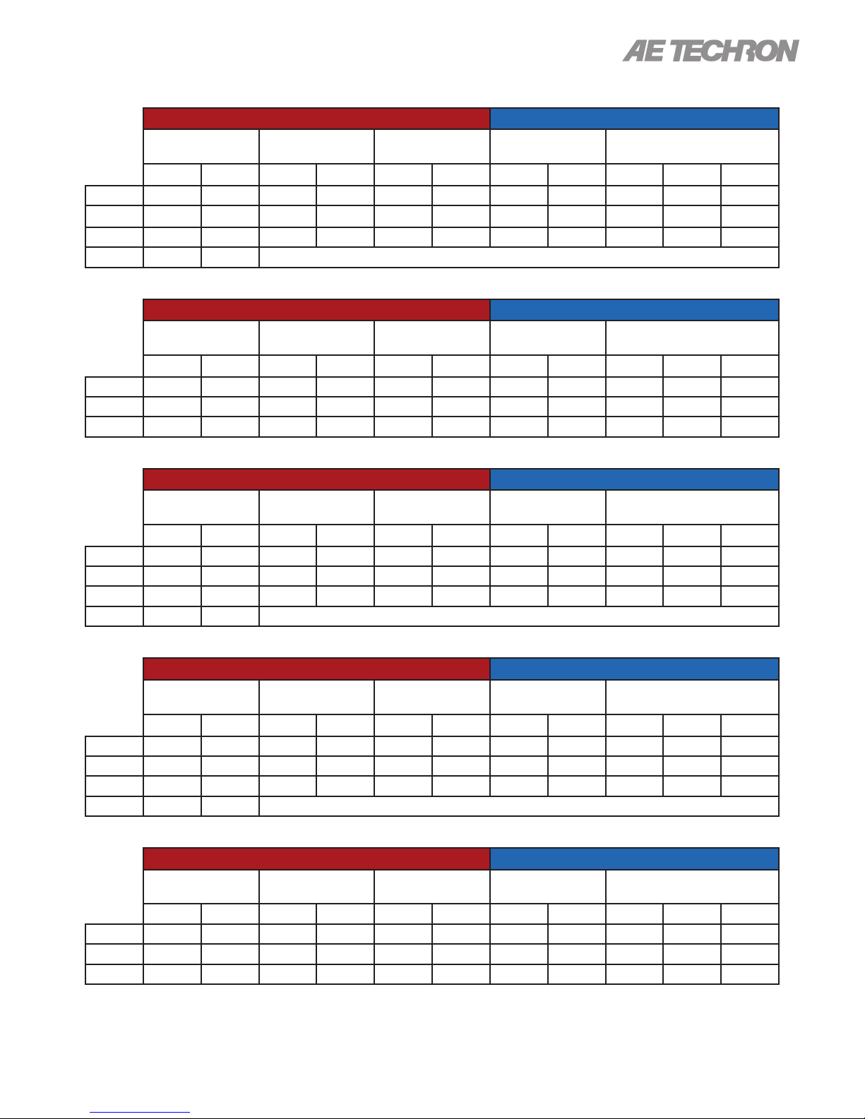
2105 OPERATOR’S MANUAL – SECTION 6
Three Paralleled 2105s – Mid-Level Mode
PEAK OUTPUT RMS OUTPUT
40 mSec Pulse,
20% Duty Cycle
Ohms Volts Amps Volts Amps Volts Amps Volts Amps Volts Amps Watts
1.34 144 54 69 49.2 69 49.2 49 34.8 49 34.8 1704
0.67 122 90 57 78.6 57 78.6 40 55.6 40 55.6 2223
0.34 94 141 43 118.8 21 63 30.4 84 14.8 44.5 659
0.167 52 156
5 Minutes,
100% Duty Cycle
Three Paralleled 2105s – High-Current Mode
PEAK OUTPUT RMS OUTPUT
40 mSec Pulse,
20% Duty Cycle
Ohms Volts Amps Volts Amps Volts Amps Volts Amps Volts Amps Watts
0.34 * * 29 87 29 87 20.5 61.5 20.5 61.5 1261
0.25 * * 26 102 26 102 18.4 72.1 18.4 72.1 1327
0.167 * * 22.7 135 22.7 135 16 95.5 16 95.5 1527
5 Minutes,
100% Duty Cycle
Four Paralleled 2105s – High-Voltage Mode
PEAK OUTPUT RMS OUTPUT
40 mSec Pulse,
20% Duty Cycle
Ohms Volts Amps Volts Amps Volts Amps Volts Amps Volts Amps Watts
4 158 39.2 158 39.2 158 39.2 112 27.7 11 2 27.7 3104
2 154 76 136 65.2 136 65.2 96 46.1 96 46.1 4425
1 124 124 108 102.8 61 58 76 72.7 43 41 1763
0.5 98 196
5 Minutes,
100% Duty Cycle
1 Hour,
100% Duty Cycle
1 Hour,
100% Duty Cycle
1 Hour,
100% Duty Cycle
5 Minutes,
100% Duty Cycle
5 Minutes,
100% Duty Cycle
5 Minutes,
100% Duty Cycle
1 Hour,
100% Duty Cycle
1 Hour,
100% Duty Cycle
1 Hour,
100% Duty Cycle
Four Paralleled 2105s – Mid-Level Mode
PEAK OUTPUT RMS OUTPUT
40 mSec Pulse,
20% Duty Cycle
Ohms Volts Amps Volts Amps Volts Amps Volts Amps Volts Amps Watts
1 144 72 69 65.6 69 65.6 49 46.4 49 46.4 2273
0.5 122 120 57 104.8 57 104.8 40.3 74.1 40.3 74.1 2986
0.25 94 188 43 158.4 21 84 30.4 112 14.8 59.4 879
0.125 52 208
5 Minutes,
100% Duty Cycle
1 Hour,
100% Duty Cycle
5 Minutes,
100% Duty Cycle
1 Hour,
100% Duty Cycle
Four Paralleled 2105s – High-Current Mode
PEAK OUTPUT RMS OUTPUT
40 mSec Pulse,
20% Duty Cycle
Ohms Volts Amps Volts Amps Volts Amps Volts Amps Volts Amps Watts
0.25 * * 29 116 29 11 6 20.5 82 20.5 82 1681
0.1875 * * 26 136 26 136 18.4 96.2 18.4 96.2 1769
0.125 * * 22.7 180 22.7 180 16 127.3 16 127.3 2036
5 Minutes,
100% Duty Cycle
1 Hour,
100% Duty Cycle
5 Minutes,
100% Duty Cycle
1 Hour,
100% Duty Cycle
97-2105006_4-2-15
Information subject to change
35
Page 36
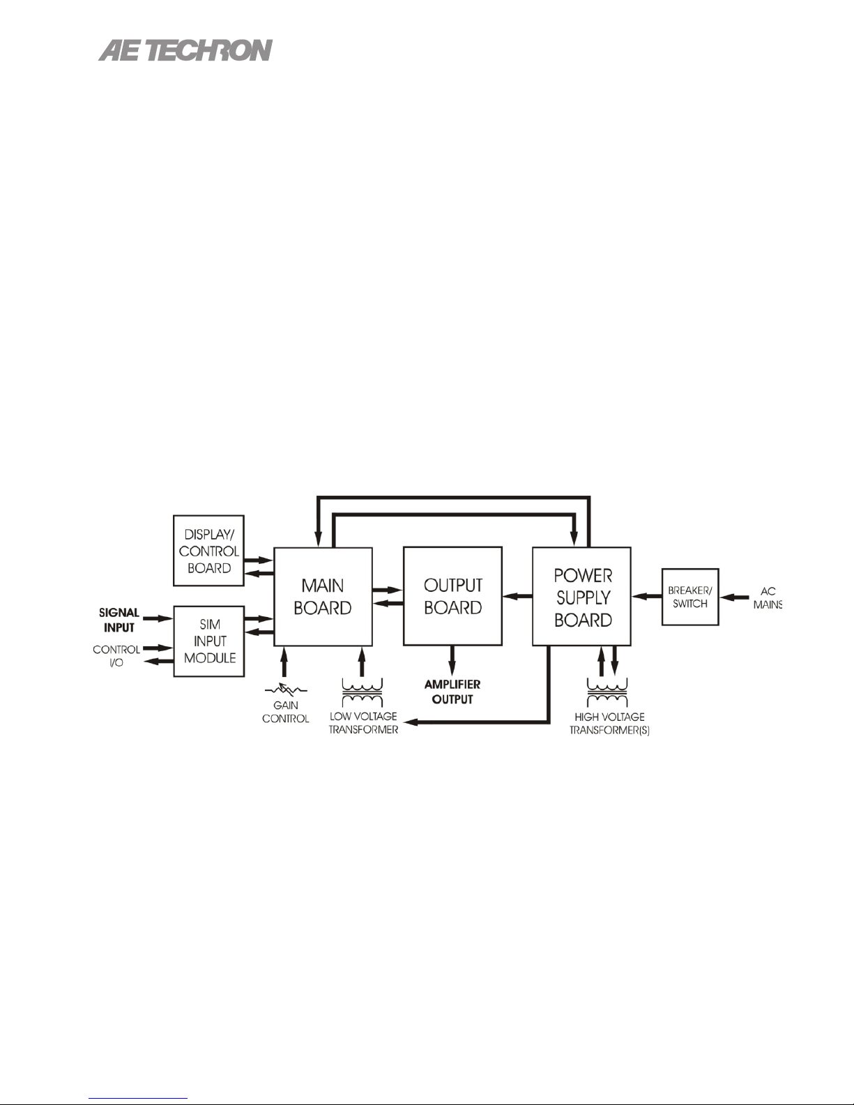
2105 OPERATOR’S MANUAL – SECTION 7
7 Amplier Signal Flow
7.1 Input Signals
The input signal is routed from the SIM (Specialized
Input Module) on the back panel to the Main board.
From there, the signal is amplied through low-noise
operational amplier gain stages, compensation
networks, and current limiting/ODEP and then nal
gain stage to the Output board. At the Output board,
the signal is sent through pre-drivers, output stage
drivers, then to the Output stage whose topology is
a full-complimentary, full-bridge, AB+B mode transis-
tor design. Amplier control and status is handled by
logic circuits tied to the Display/Control board on the
front panel. Protection is provided by current limiting
circuits and special junction temperature simulation
circuits using thermal feedback from the main heat
sinks on the Output board.
7.2 AC Mains Power
Power to the amplier is connected through a 20-
amp IEC-type inlet connector with an integral EMI
lter network on the back panel. AC mains power is
rst routed through the front panel switch/breaker,
then to the Power Supply board. From there, the AC
mains are distributed to the main power transform-
ers, and then from the transformers back through the
Power Supply board to the Main board.
The Power Supply board allows for easy congura-
tion of primary and secondary voltages. The Power
Supply board also performs the “bi-level” function.
This allows the power supply rails to the Output sec-
tion to increase or decrease depending on demand
and keeps the voltage dropped across the outputs to
a minimum, thereby decreasing heat dissipation.
Figure 7.1 – Board-Level Functional Block Diagram
36
Information subject to change
97-2105006_4-2-15
Page 37
2105 OPERATOR’S MANUAL – SECTION 8
8 Maintenance
Simple maintenance can be performed by the user
to help keep the equipment operational. The following routine maintenance is designed to prevent
problems before they occur. See Section 8, Trou-
bleshooting, for recommendations for restoring the
equipment to operation after an error condition has
occurred.
Preventative maintenance is recommended after
the rst 250 hours of operation, and every three
months or 250 hours thereafter. If the equipment
environment is dirty or dusty, preventative mainte-
nance should be performed more frequently.
CAUTION
Before you begin, make sure your amplier is disconnected from the power
source, with power switch in the OFF
position and the level control turned
completely down (counter-clockwise).
8.1 Clean Amplier Filter and Grills
8.1.1 Tools Required
The recommended equipment and supplies
needed to perform the functions required for this
task are described below.
• Vacuum cleaner
• Damp cloth (use water only or a mild soap
diluted in water)
To ensure adequate cooling and maximum efciency of the internal cooling fans, the amplier’s
front and rear grills should be cleaned periodically.
To clean the amplier grills and lter, complete the
following steps:
1. Turn completely down (counter-clockwise) all
level controls and turn the amplier OFF. Disconnect the amplier from its power source.
2. Using a vacuum cleaner, vacuum the front ventilation grill, including the lter behind the grill,
and the back ventilation exit grill.
3. Using a damp cloth, clean the front and rear
ventilation grills. Dry with a clean cloth or allow
to air dry. IMPORTANT: Grills should be com-
pletely dry before plugging in or restarting
amplier.
97-2105006_4-2-15
Information subject to change
37
Page 38
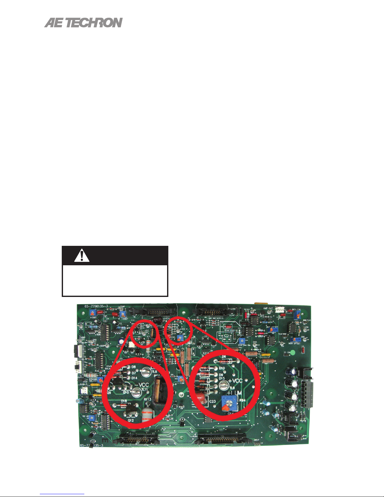
2105 OPERATOR’S MANUAL – SECTION 9
9 Troubleshooting
9.1 Introduction & Precautions
This section provides a set of procedures for
identifying and correcting problems with the 2105
amplier. Rather than providing an exhaustive and
detailed list of troubleshooting specications, this
section aims to provide a set of shortcuts intended
to get an inoperative amplier back in service as
quickly as possible.
The procedures outlined in this section are direct-
ed toward an experienced electronic technician;
it assumes that the technician has knowledge of
typical electronic repair and test procedures.
Please be aware that the 2105 will undergo frequent engineering updates. As a result, modules
and electronic assemblies may not be interchange-
able between units. Particularly, the Main board
undergoes periodic engineering modications that
may make interchangeability between units impos-
sible.
DANGER
Uninsulated terminals with AC Mains
potential are exposed when the panel is
removed. Do not proceed until AC Mains
have been disconnected.
9.2 Visual Inspection
Before attempting to troubleshoot the amplier
while it is operating, please take time to complete
a visual inspection of the internal components of
the amplier.
1. To perform a Visual Inspection, rst turn the
Breaker/Switch to the Off (O) position.
2. Disconnect the AC mains plug from the amplier.
3. Wait three to ve minutes for the Power Supply capacitors to discharge. You can verify the
capacitor discharge by connecting a voltmeter
across +Vcc and –Vcc test points on the main
board (see Figure 9.1). Verify a reading of less
than 50 volts before proceeding.
4. Inspect the amplier’s internal components.
Check the following:
5. Inspect modules for charring, breaks, deformation or other signs of physical damage.
6. Look for any foreign objects lodged inside the
unit.
7. Inspect the entire lengths of wires and ribbon
cables for breaks or other physical damage.
8. If there is any physical damage to the amplier,
please return it to AE Techron for repair.
38
Figure 9.1 – +Vcc and –Vcc Point Locations
Information subject to change
97-2105006_4-2-15
Page 39
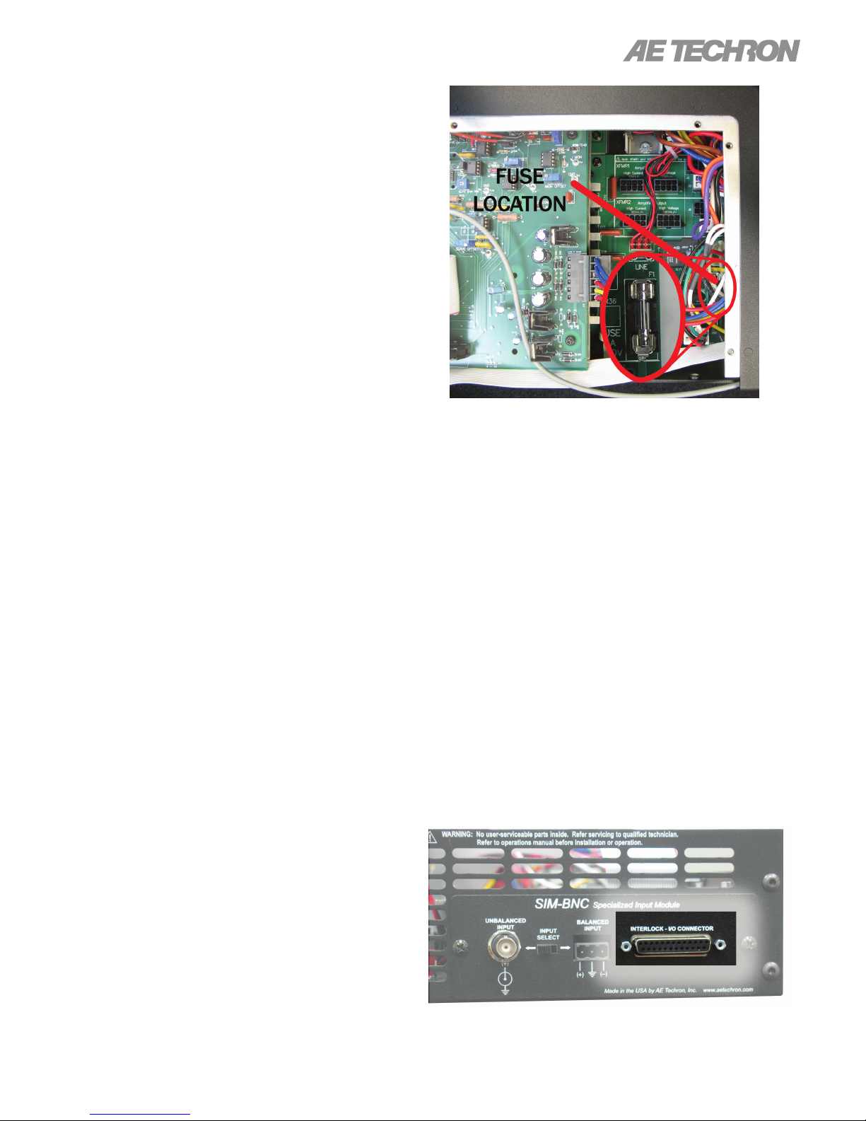
2105 OPERATOR’S MANUAL – SECTION 9
9.3 No Signal
Missing Output signal may be caused by one of
the following:
1. Master/Slave Jumpers are set to the Slave
(down) position. The amplier should only be
congured for Slave mode if it is in a multi-amplier system; otherwise it should be set for Master
mode. See the “Advanced Conguration” section in this manual for more information.
2. Signal is not connected to any inputs on the
SIM card. See the “Amplier Setup” section
in this manual for more information.
9.4 No LEDs Illuminated or No Fans
If none of the LEDs on the Display Panel are illuminated and/or the fans are inoperative, check
the following:
1. The AC mains are not connected or not on
(see the “Amplier Setup” section for more
information).
2. Front Panel Breaker/Switch has been tripped.
Reset by turning the unit Off (O) and then On.
3. Fuse F1 is open.
To Inspect Fuse F1 follow these steps:
1. Turn Off (O) the amplier and disconnect the
AC mains.
2. Remove Access Panel (see “Advanced Con-
guration”).
3. Locate Fuse F1 (see Figure 9.2). Remove fuse
and inspect. Replace, if necessary, with same
type fuse (T1.6A L 250V).
9.5 OverVoltage LED Lit
Figure 9.2 – Fuse F1 Location
9.6 Standby LED Remains Illuminated
The Standby indicator may remain illuminated
under three conditions:
1. If the output wells or power transformer have
overheated. If overheating is the problem, see
the following topic (“Amplier Overheats”).
2. If both the Standby and Ready LEDs remain
illuminated and the Interlock I/O Cable is being
used, the amplier is being held in Remote
Standby mode by another device (see Figure
9.3). For more information on 2105 Remote
Operation, see the “Applications” section in
this manual.
3. If the connection to the Interlock – I/O Connec-
tor or other input/output connection isn’t fully
secure. Check all wiring and connections.
The amplier will protect itself from AC mains voltage that is 10% above the voltage indicated on
the back panel. If the AC mains voltage is more
than 10% above the operating voltage, reduce the
AC mains voltage to the proper level. When the
line voltage condition is corrected, the amplier
will automatically reset. If the amplier does not
automatically reset, the amplier’s three internal
transformers may need to be rewired. Please see
the Factory Service information at the end of this
section.
97-2105006_4-2-15
Figure 9.3 – Interlock I/O Connector
Information subject to change
39
Page 40
2105 OPERATOR’S MANUAL – SECTION 9
9.7 Amplier Overheats (Over Temp
Fault Condition)
There are two possible reasons why the 2105 am-
plier is overheating:
1. Excessive Power Requirements
2. Inadequate Airow
9.7.1 Excessive Power Requirements
An amplier will overheat if the required power exceeds the amplier’s capabilities. High duty cycles
and low-impedance loads are especially prone to
cause overheating. To see if excess power requirements are causing overheating, check the following:
1. The application’s power requirements fall
within the specications of the amplier. See
the “Specications” section.
2. Faulty output connections and load.
3. Undesired DC offset at the Output and Input
signal.
the input signal from the amplier. Allow the fans to
run for ve minutes, and then push the Reset button to reset the amplier.
9.8 Fault LED is Illuminated
The 2105 contains protection circuitry that disables
the amplier if an output stage is behaving abnormally. This usually indicates an output transistor
has shorted.
To clear the Fault condition, follow these steps:
1. Turn off the signal source.
2. Turn off the AC mains.
3. Turn AC mains power back on. If the Fault LED
doesn’t illuminate again, turn the signal source
on.
4. If the Fault LED is still illuminated and the Fault
condition doesn’t clear, return the amplier for
Factory Service. Please see the Factory Service information at the end of this section.
If the amplier chronically overheats with suitable
power/load conditions, then the amplier may not
be receiving adequate airow. To check for adequate airow, proceed with the following step:
9.7.2 Check for Inadequate Airow
1. Check air lters. Over time they can become
dirty and worn out. It is a good idea to clean
the air lters periodically with a mild detergent
and water.
2. Visually inspect fans to assure correct opera-
tion while amplier is On (I).
Any inoperative, visibly slow, or reverse-spinning
fan should be replaced. Please see Section 8.9
for Factory Service information.
An OverTemp condition places the amplier in
Standby mode. If the OverTemp pulse is ex-
tremely short, as in the case of defective wiring or
switches, the OverTemp pulse may be too brief to
observe.
9.7.3 Resetting After OverTemp
To reset the amplier after an OverTemp has occurred, make sure fans are running, then remove
CAUTION
Shut off the signal source before reset-
ting the amplier. Try resetting the Fault
condition only once. If the Fault condi-
tion does not clear after one reset, STOP.
Contact AE Techron Support for further
assistance. repeated resetting can dam-
age the amplier.
9.9 Factory Service
If the troubleshooting procedures are unsuccessful, the amplier may need to be returned for
Factory Service. All units under warranty will be
serviced free of charge (customer is responsible
for one-way shipping charges as well as any custom fees, duties, and/or taxes). Please review the
Warranty at the beginning of this manual for more
information.
All service units must be given Return Authorization by AE Techron, Inc. before being returned.
Return Authorizations can be requested on our
website or by contacting our Customer Service
Department.
40
Information subject to change
97-2105006_4-2-15
Page 41

2105 OPERATOR’S MANUAL – SECTION 9
Please take extra care when packaging your amplier for repair. It should be returned in its original
packaging or a suitable alternative. Replacement
packaging materials can be purchased for a nomi-
nal fee.
Please send all service units to the following address and be sure to include your Return Authori-
zation Number on the box.
AE Techron, Inc.
Attn: Service Department / RMA#
2507 Warren Street
Elkhart, IN 46516
97-2105006_4-2-15
Information subject to change
41
Page 42

2105 OPERATOR’S MANUAL – SECTION 10
10 Specications
2105 Pulsed Output - Current Mode
PULSE DURATION / OFF TIME (mS)
DC* 500 / 500 100 / 100 10 / 20 170 / 1000 25 / 1000 4 / 100
Output (±A Peak) 16 8.75 9 11.7 25 49 55
*DC 1Ω
10.1 Performance
Specication typical at 25°C ambient. Unless otherwise noted; testing was done in Current mode with a load = 500 µH +100 mΩ.
Peak Current Limit 55 A
Gain (adjustable) Voltage Mode: 20 to 0.2 V/V
Current Mode: 5 to 0.2 A/V
Gain Linearity DC: 0.02%
(over input signal, from 0.2V to 5V) AC: 0.05%
Output Offset (adjustable to zero) Voltage Mode: Less than ±400 µV
Current Mode: ±5 mA
Input Characteristics Three-Terminal Barrier Block Connector:
Balanced with ground; 20 kΩ differential
BNC Connector: Unbalanced; 10 kΩ single ended
Max Input Voltage: ± 10 V balanced or unbalanced
Common Mode Rejection: –58 dB with 5 V input
Output Impedance Current Mode (effective): 2000 Ω
Voltage Mode (typical): 28 mOhm in series with 1 µH
Load Current Mode:
500 µH + 100 mΩ
Adaptable Range: 5 µH to 2.5 H, 0.01 Ω to 20 Ω
Current Mode Response –3 dB at 10 kHz (compensation dependent)
Current Settling Time Ramp 0 A to ±50 A or ±50 to 0 A:
20 µs to within 1.0 A or 1%
35 µs to within 200 mA, 0.2%
Total Harmonic Distortion Current Mode: Less than 0.1%
Load: 500 µH + 100 mΩ
Noise Floor (when Blanking circuit is enabled) 5 µA or less
DC Drift Self Heating Drift, 0 to ±60 A:
5 mA/10 minutes maximum
Noise Output 10 Hz to 1 kHz: 0.2 mA
1 kHz to 60 kHz: 0.05 mA
Ripple Noise Output None
Slew Rate, Voltage Mode: 23 V/µs
Remote Control and Monitoring Current Monitor: ± 1 V / 5 A ± 1%
(back-panel D connector) Reporting: System Fault, Over Temp, Over Voltage, Over
Control: Force to Standby, Remove from Standby,
42
Load
Reset after a Fault
Information subject to change
97-2105006_4-2-15
Page 43

2105 OPERATOR’S MANUAL – SECTION 10
Amplier Protection Over Load/Distortion (IOC): Shutdown or clipped
output
Current vs Time (ODEP): Clipped output
Each heat sink temperature: Shutdown 105°C
Overvoltage Shutdown: 132 VAC / 253 VAC
Undervoltage Shutdown: 108 VAC / 207 VAC
Status Indicators (front panel) LEDs indicate a status of Run, Ready or Standby,
and Fault, Over Temp, Over Voltage, and Over Load
conditions
Controls (front panel) Soft Touch Switches: Run (Enable), Stop and Re-
set functions
Gain Control, when-enabled: Voltage gain adjustable from 20 to 0; Current gain adjustable from 5 to 0
On/Off and Breaker: Two-position power switch also
functions as a breaker; turn off and then on to reset
Connectors (back panel) Power Connection: 25-amp IEC (with retention
latch)
Signal Output: Three terminal barrier strip (OUTPUT/COM/CHASSIS GROUND); resistor installed
between COM and CHASSIS GROUND terminals is
a 2.7-ohm, 2W, 5%, metal-oxide resistor
Signal Input: User-selectable unbalanced BNC or
balanced Barrier Strip
Interlock I/O Connection: 25-pin D connector pro-
vides for remote monitoring and control functions
Power Requirements Single phase, 120 VAC, 60 Hz, 20 Amp service;
(220-240 VAC, 50-60 Hz, 10 Amp service model
available)
Thermal Requirements Operating Temperature: +10°C to +30°C (+50°F to
+86°F).
Storage: –30°C to +85°C (–22°F to +185°F)
Humidity: 70% or less, non-condensing
Physical Characteristics Dimensions: 19” L x 3.5” H x 22.75” D (48.3 cm L x
8.9 cm H x 57.8 cm D)
Cooling: Forced air cooling from front to back
through removable lters.
Airow: 180CFM
Weight: 41 lbs (18.6 kg)
Shipping Weight: 51 lbs (23.2 kg)
97-2105006_4-2-15
Information subject to change
43
Page 44
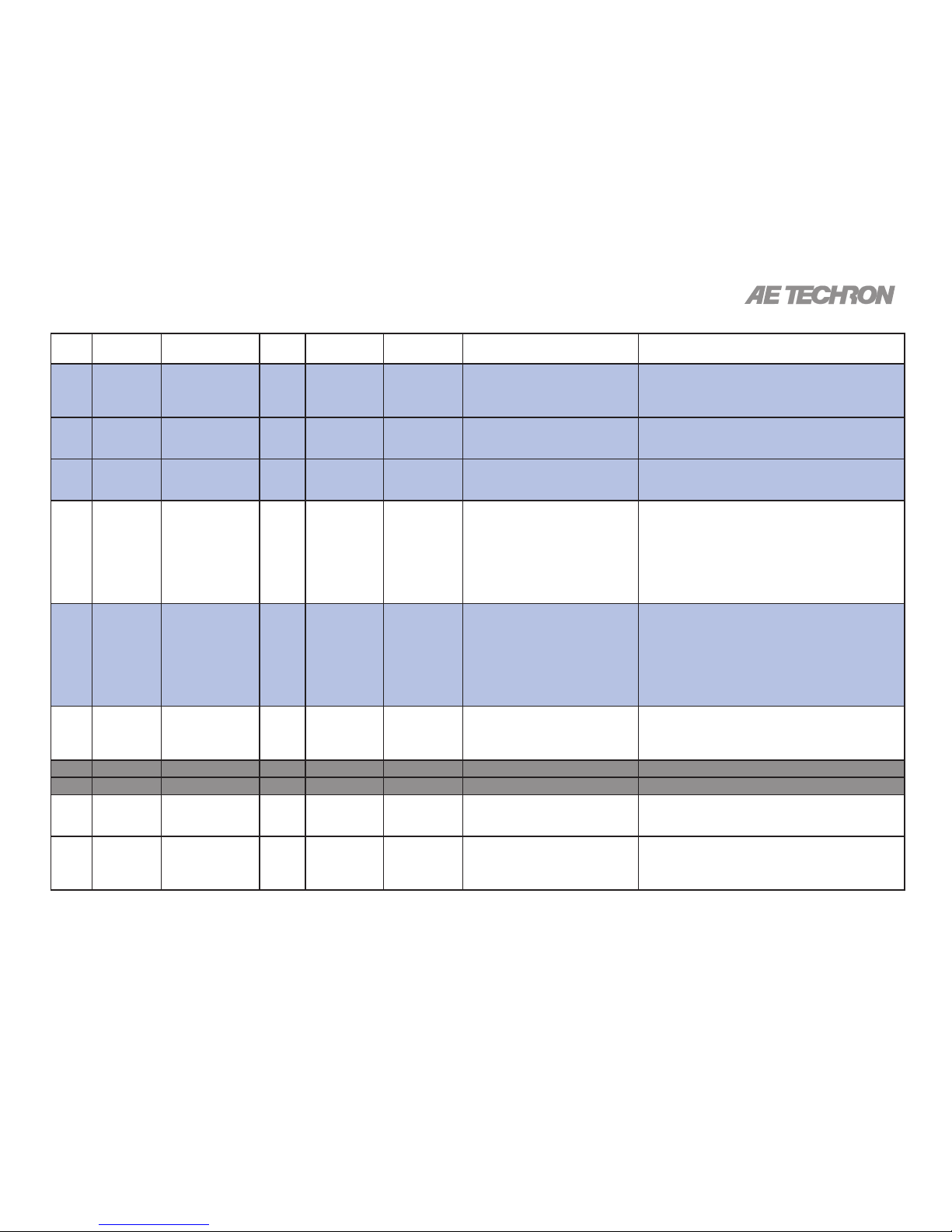
A1
Pin # Function Description Signal
Type
Level when
Asserted
Level when
Deasserted
Notes Applications
1
Amplier
Output
Used for driving
slave ampliers;
monitoring amplier output voltage
AC or DCCan be greater
than ±200V
peak
0V Used for driving slave ampliers in
multi-amp systems. Wired to ampli-
er output. Do not connect to any
impedance of less than 10K ohm.
Used in multi-amplier systems.
2
Sampled
Common
Load connected
here for Current
sense
AC or DCUp to ±2V
peak relative
to Common
0V Used for driving slave ampliers in
multi-amp systems, controlled volt-
age or controlled current mode.
Driving Slave Ampliers: Amplier External Reference,
2V peak maximum from PIN 14 (Common).
3
+1 IN Differential Slave
input
AC or DCCan be greater
than ±200V
peak
0V Only used in multiple amplier con-
gurations - Series mode.
Can accept output of PIN 1 (Amplier Output) OR PIN 2
(Sampled Common) from Master device when in Slave
mode.
4
Interlock Amplier Interlock
input
DC 0V to 8V 10V to 15V When “low”, forces to Standby;
when allowed to oat, allows Run (if
amplier is “Ready”). IMPORTANT:
ampliers must be congured for
Run mode at startup (factory default)
or the Run button must be pressed
at the amplier front panel at startup.
Remote to Standby: Short PIN 4 of amplier to Digital
Ground (PIN 17) using dry contact switch or optocoupler.
When closed, places amplier in Standby.
Multi-amplier Systems, Simultaneous Enable or
Disable of ampliers: Daisy-chain Interlock (PIN4)
across amps (if sharing the same Sampled Common
power connections). Optocoupler must be used for multi-
amps in series.
5
Amp Ready Ready output of
amplier
DC 0V –14V Normally reserved for OPTOC
use; not recommended for normal
customer use. Line has series
resistor and unloaded will go from
0V (not ready) to -15V (ready), with
an OPTOC BNC card the signal will
go from 0V (not ready) to -1.2Vdc
(ready)
Not recommended for normal customer use.
6
I MON + Differential Current
Monitor +
AC or DC2105: 5A/V
2110/2120:
20A/V
Output current produced per voltage
detect.
Current Monitoring: Connect a voltage meter to monitor the output current being produced by the amplier.
For unbalanced, for each 1V detected, current output is
5A (2105) or 20A (2110/2120).
7
None No connection Not currently used.
8
None No connection Not currently used.
9
Blanking
input
Blanking control DC 0 - 1Vdc
allows normal
operation
3.5 - 5Vdc output is muted
Used in ampliers with blanking
feature for blanking control.
Blanking Control: Use an external isolated 5V power
supply to mute the output of the amplier.
10
Sampled
Common
Amp Analog
Ground; Blanking
Ground
Amplier ground. Can be used as Blanking return or as a reference of the
amplier for status reporting applications. See OverTemp (PIN 11), Run (PIN 12), Overload (PIN 23), and
OverVoltage (PIN 24).
Appendix A: SIM - Interlock I/O Connector Pinouts and Functions
Page 45
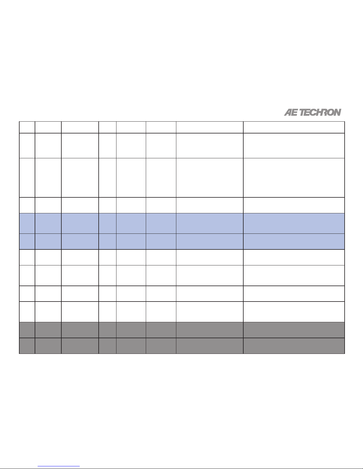
A2
Pin # Function Description Signal
Type
Level when
Asserted
Level when
Deasserted
Notes Applications
11
OverTemp
Out
Over-temperature
output
DC –24V 0V When amp is normal, this pin is
pulled to –24V through a 47.5K-ohm
resistor; when amp is in OverTemp
state, this pin is grounded. Do not
exceed 7 milliamps.
Remote Signal of Over-Temperature Condition: LED,
when lit, signals Over Temperature condition. Use a 6
mA series resistor of 4.7K-ohm for LED or OPTO, tie to
–24V source (PIN 13).
12
Run Amplier Run
output
DC –24V 0V When amp is in Standby mode, this
pin is pulled to –24V; when amp is in
Run mode, this pin is grounded, energizing Mains Relays and allowing
drive for an external LED.
DO NOT exceed 7mA; DO NOT
ground this pin as this will enable
Main Power Relays.
Remote Signal of Run Condition: LED, when lit, signals Run state. Use a 6mA series resistor of 4.7K-ohm
for LED or OPTO, tie to –24V source (PIN 13).
13
–24V –24V Power
Output
DC –24V dc, 30 mA max Internally tied for use in status reporting applications.
See OverTemp (PIN 11), Run (PIN 12), Overload (PIN
23), and OverVoltage (PIN 24).
14
Common Ground before
Sense Resistors
Current monitor reference. Voltage
between Common and Sampled
Common is voltage on the Current
Sense resistor.
Possibly series ampliers will not need current reporting
on the High side amp, since its current will be same as
Master.
15
–1 IN Differential Slave
Input
AC or DCUp to 200V
peak
0V Only used in multiple amplier con-
gurations, Series mode.
Can accept output of PIN 1 (Amplier Output) OR PIN 2
(Sampled Common) from Master device when in Slave
mode.
16
+24V +24V Power
Output
DC +24V dc, 30 mA max. Used in status reporting applications. See OverTemp
(PIN 11), Run (PIN 12), Overload (PIN 23), and OverVoltage (PIN 24).
17
Digital
Ground
Digital circuitry
ground - Interlock
Common
DC 0V 0V Used with PIN 25 (Reset) for Remote Reset from
Standby or Stop after Error. Used with PIN 4 (Interlock)
for simultaneous remote to Standby of all amps in a
multi-amplier system.
18
OEM App Input Monitor
(OEM only)
Used to monitor the input signal
from an OEM DAC card; this is the
actual input signal.
OEM modication only; normally no connection.
19
I MON –
(alt.: OEM
App)
Differential Current
Monitor – ;
(- Input Monitor,
OEM only)
AC or DC2105: 5A/V
2110/2120:
20A/V
Inverted I MON+ (PIN 6). Output
current produced per voltage detect.
Current Monitoring: Connect a voltage meter to monitor the output current being produced by the amplier.
For each 1V detected, current output is 5A (2105) or 20A
(2110/2120).
20
I SUM1– Multiple Amplier
Summing, Amplier
1
DC Planned for use in multiple amplier
congurations - paralleled and running Controlled Current Mode
Currently not used.
21
I SUM2– Multiple Amplier
Summing, Amplier
2
DC Planned for use in multiple amplier
congurations - paralleled and running Controlled Current Mode
Currently not used.
Page 46
A3
Pin # Function Description Signal
Type
Level when
Asserted
Level when
Deasserted
Notes Applications
22
I SUM3– Multiple Amplier
Summing, Amplier
3
DC Planned for use in multiple amplier
congurations - paralleled and running Controlled Current Mode
Currently not used.
23
OverLoad
Out
Overload output
(amplier output is
clipping).
DC –24V 0V When amp is normal, this pin is
pulled to –24V through a 47.5K-ohm
resistor; when amp is in Overload
state, this pin is grounded. Do not
exceed 6 milliamps.
Remote Signal of Overload Condition: LED, when lit,
signals Overload condition. Use a 6mA series resistor
of 4.7K-ohm for LED or OPTO, tie to –24V source (PIN
13).
24
OverVoltage
Out
Overvoltage output
(High AC line
voltage).
DC –24V 0V When amp is normal, this pin is
pulled to –24V through a 47.5K-ohm
resistor; when amp is in Overvoltage
state, this pin is grounded. Do not
exceed 6 milliamps.
Remote Signal of Overvoltage Condition: LED, when
lit, signals Overvoltage condition. Use a 6mA series resistor of 4.7K-ohm for LED or OPTO, tie to –24V source
(PIN 13).
25
Reset Reset DC –15V 0V Tie to PIN 13 (–24V dc) and create a
–15V dc source; <2mA required for
reset. Connect the –15V dc source
to PIN 25 (Reset) through a 1K
buffer resistor to reset.
Reset from Standby: Use a dry contact switch and voltage regulator to return amp to Ready/Run condition after
Over-temperature or Overload conditions. Assert –15V
for at least 100 ms to clear error condition.
Gray shaded areas indicate pin not used / feature not implemented. Blue shaded areas indicate used only in multi-amplier systems.
 Loading...