

Aesthetix Atlas User Manual

A
S
TLA
Hybrid Power Amplifier
Owner’s Manual
For both Stereo and Mono Amplifiers
PLEASE READ THIS DOCUMENT IN ITS ENTIRETY BEFORE
USING THE ATLAS.
Aesthetix Audio Corporation
5220 Gabbert Rd., Suite A ♦ Moorpark, CA. 93021
Phone: (805) 529-9901
The lightning flash with arrowhead symbol, within an equilateral triangle,
is intended to alert the user to the presence of uninsulated “dangerous
voltage” within the product’s enclosure that may be of significant
magnitude to constitute a risk of electric shock to persons.
The exclamation point within an equilateral triangle is intended to alert
the user to the presence of important operating and maintenance
(servicing) instructions in the literature accompanying the product.
WARNING
TO REDUCE THE RISK OF FIRE OR ELECTRIC SHOCK,
DO NOT EXPOSE THIS PRODUCT TO RAIN OR MOISTURE
CAUTION: TO PREVENT ELECTRIC SHOCK, DO NOT USE THE AC (POLARIZED) PLUG WITH AN
EXTENSION CORD, RECEPTACLE OR OTHER OUTLET UNLESS THE BLADES CAN BE FULLY INSERTED
TO PREVENT BLADE EXPOSURE.
Extension cords are not recommended for use with this product.
2
PREFACE
INTRODUCTION
Thank you for purchasing the Atlas power amplifier. It has been engineered to deliver the highest
attainable sound quality from your music sources. This is its sole purpose. Only the highest grade electronic
components are used in the Atlas, including: non-inductive Roederstein metal film resistors in the signal path;
polystyrene, polypropylene, and electrolytic power supply, bypass, and signal capacitors; low noise matched
vacuum tubes; glass epoxy dual mono circuit boards; 16 gauge aluminum chassis; custom wound low flux
power transformers.
PLACEMENT
The Atlas main unit should be located away from possible sources of hum such as power cords, power
transformers and the like. It should not be located near any other heat source such as another power amplifier
or power supply. It must be kept well ventilated any time it is on. If it is positioned within an enclosed space
then fans may be warranted. All air vents must remain unobstructed.
BURN IN TIME
This unit has a break in period of about 1 month during which continuous improvement in sound quality will
be observed.
IMPORTANT
Save all packaging in a dry place away from fire hazards. Your Atlas is a precision electronic instrument and
should be properly packaged any time shipment is made. In the unlikely event that you have to return your
Atlas to the factory for service, or if you send it to us for updating, the original packaging will best protect the unit
from shipping damage.
In order to achieve the fullest flexibility and enjoyment from your Atlas, we at Aesthetix recommend that you
read this manual in full before connecting the unit to your audio system.
Note: It is imperative that the Atlas be operated in a well ventilated environment and the immediate external
temperature be maintained as specified. External cooling fans may be required in some cases. Do not
stack any equipment directly above or below the Atlas to protect it from overheating, as well as the
Warning: Each channel is a balanced bridge amplifier, thus the negative speaker terminal is NOT a ground,
United States law prohibits disposition of these commodities to Libya, Laos, North Korea, Cambodia or Cuba
unless otherwise authorized by the United States.
AFTER MARKET and THIRD PARTY MODIFICATIONS
Please note that any after market and/or third party modifications will void the warranty. In the case of changing
the feet on a unit, in order to prevent any damage (which will also not be covered under warranty), please verify
that the screws being used to secure non-Aesthetix feet do not screw any deeper into the chassis than the
original ones. The original screw is 10-32 by 3/8” and extends into the chassis 1/8 inch.
Manual Conventions
All information contained in this document applies for both the Stereo and Mono Atlas models, unless otherwise
specified.
For clarity purposes, references to buttons, LEDs and menu data will be shown in bold capital letters.
© 2007 Aesthetix Audio Corporation. All rights reserved. Written and Illustrated by Glenn Buckley
No part of this publication may be reproduced or transmitted in any form or by any means, electronic or
mechanical, for any purpose, without the express written permission of Aesthetix Audio Corporation.
continued functionality of any equipment near and around it.
and cannot be connected to a system ground or a loudspeaker system with a common ground.
Consult your speaker manufacturer to ensure that any speaker in your system that will be
connected to the Atlas does NOT have internal circuitry with a common ground.
WARNING
3

SAFETY PRECAUTIONS
Please carefully read each item of the operating instructions and safety precautions before installing and using
this product. Use extra care to follow the warnings written on the product itself and/or in the operating
instructions. Keep the operating instructions and safety precautions for future reference.
CAUTION: TO REDUCE THE RISK OF ELECTRICAL SHOCK, DO NOT REMOVE ANY OF THE COVER
PANELS.
NO USER-SERVICEABLE PARTS INSIDE. REFER ALL SERVICING TO QUALIFIED SERVICE
PERSONNEL ONLY.
TO PREVENT FIRE OR SHOCK HAZARD, DO NOT ALLOW LIQUIDS TO SPILL OR OBJECTS TO FALL
INTO ANY OPENINGS OF THE PRODUCT.
THIS UNIT IS SUPPLIED WITH A 3 PIN GROUNDED AC PLUG. ALWAYS INSERT THE AC PLUG INTO A
GROUNDED OUTLET. DO NOT REMOVE THE GROUND PIN OR DISABLE THE GROUND FOR ANY
PURPOSE.
BEFORE MAKING ANY CONNECTIONS TO THE ATLAS, FIRST TURN OFF THE POWER AND THEN
DISCONNECT THE AC POWER CORD.
WHEN INSTALLING THE ATLAS IN YOUR SYSTEM, MAKE CERTAIN TO ALLOW A MINIMUM OF 4
INCHES OF VENTILATION ON EACH SIDE OF THE UNIT. ALSO ALLOW AT LEAST 6 INCHES OF
VENTILATION SPACE ABOVE THE UNIT. IMPROPER VENTILATION OF THE UNIT MAY CAUSE
OVERHEATING, WHICH MAY DAMAGE THE UNIT AND CAUSE A FIRE. PLACE THE UNIT ON A SOLID
SURFACE ONLY. I.E. NOT ON CARPET, ETC.
DO NOT PLACE THE ATLAS NEAR HEAT SOURCES SUCH AS DIRECT SUNLIGHT, STOVES, HEAT
REGISTERS, RADIATORS OR OTHER HEAT PRODUCING EQUIPMENT.
TO PREVENT DAMAGE TO THE ANALOG OUTPUT CIRCUITRY, BE CERTAIN NOT TO SHORT THE
OUTPUT SIGNAL TO GROUND. ENSURE THAT YOUR AUDIO OUTPUT CABLES DO NOT HAVE ANY
INTERNAL SHORTS BEFORE CONNECTING THEM TO THE ATLAS.
IF REPLACEMENT OF THE AC LINE FUSE AND/OR ANY INTERNAL FUSE BECOMES NECESSARY,
REPLACE ONLY WITH SAME VALUE AND TYPE OF FUSE. NEVER BYPASS THE FUSE.
IF THE AC CORD BECOMES DAMAGED, DO NOT USE IT. IMMEDIATELY REPLACE IT WITH A NEW
ONE OF THE SAME OR BETTER RATING.
IT IS IMPERATIVE THAT THE ATLAS BE OPERATED IN A WELL VENTILATED ENVIRONMENT AND THE
IMMEDIATE EXTERNAL TEMPERATURE BE MAINTAINED AS SPECIFIED. EXTERNAL COOLING FANS
MAY BE REQUIRED IN SOME CASES. DO NOT STACK ANY EQUIPMENT DIRECTLY ABOVE OR
BELOW THE ATLAS AS TO PROTECT IT FROM OVERHEATING, AS WELL AS THE CONTINUED
FUNCTIONALITY OF ANY EQUIPMENT NEAR AND AROUND IT.
EACH CHANNEL IS A BALANCED BRIDGE AMPLIFIER, THUS THE NEGATIVE SPEAKER TERMINAL IS
A GROUND, AND CANNOT BE CONNECTED TO A SYSTEM GROUND OR LOUDSPEAKER SYSTEM
NOT
WITH A COMMON GROUND. CONSULT YOUR SPEAKER MANUFACTURER TO ENSURE THAT ANY
SPEAKER IN YOUR SYSTEM THAT WILL BE CONNECTED TO THE ATLAS DOES NOT HAVE INTERNAL
CIRCUITRY WITH A COMMON GROUND.
IF THE TOP COVER HAS TO BE REMOVED, FIRST TURN OFF THE REAR PANEL POWER SWITCH AND
WAIT 15 MINUTES. THEN REMOVE THE TWO 6-32 PANHEAD SCREWS AT THE TOP OF THE REAR
PANEL AND LIFT THE BACK OF THE TOP COVER UPWARDS.
4

Table Of Contents
PREFACE............................................................................................................................3
INTRODUCTION..............................................................................................................3
PLACEMENT....................................................................................................................3
BURN IN TIME.................................................................................................................3
IMPORTANT....................................................................................................................3
WARNING........................................................................................................................3
SAFETY PRECAUTIONS ...................................................................................................4
Table Of Contents ...............................................................................................................5
Front Panel Layout..............................................................................................................6
Rear Panel Layout...............................................................................................................7
CONNECTIONS...............................................................................................................9
OPERATION .......................................................................................................................9
STANDBY.........................................................................................................................9
SELECTING INPUTS.....................................................................................................10
CROSSOVER.................................................................................................................10
MUTE .............................................................................................................................10
REMOTE TRIGGER.......................................................................................................10
RS232.............................................................................................................................11
Appendix A Troubleshooting Guide .................................................................................12
Display Codes ................................................................................................................12
Appendix B Wiring Diagrams...........................................................................................13
Appendix C Block Diagram..............................................................................................15
Appendix D RS232 Protocol.............................................................................................16
Appendix E Specifications ..............................................................................................17
5
Front Panel Layout
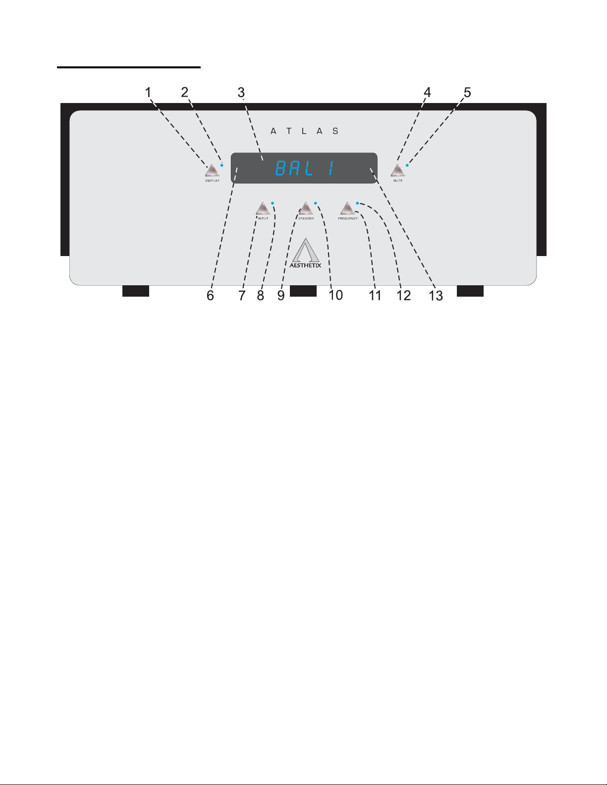
Figure 1 - Front Panel Layout – Stereo and Mono versions
1. DISPLAY button. Press to extinguish or turn on the display, set display brightness.
2. Display LED. Not used.
3. LED DISPLAY
4. MUTE button. Toggle to mute or unmute the Altas.
5. Mute LED. Illuminates when the Mute function is active.
6. Pressing the left side of the DISPLAY will decrement the value when in a submenu.
7. INPUT button. Used to select the appropriate rear panel input connector. Ensure that this is set correctly.
8. INPUT LED. Illuminates when the INPUT menu is active.
9. STANDBY button. After the rear panel MAIN POWER switch is turned on press the front panel STANDBY
button to exit the standby mode. Pressing this button again will put the Atlas into
STANDBY and illuminate the Standby LED.
10. Standby LED. Illuminates Red when the Atlas is in Standby, Blue when the Atlas is active (out of standby).
11. FREQUENCY button. Press to enter the crossover frequency selection menu.
12. Frequency LED. Illuminates when the Frequency menu is active.
13. Pressing the right side of the DISPLAY will increment the value when in a submenu.
6
 Loading...