

Aesculap PV440 Camera System User manual

Aesculap®
Aesculap Endoscopic Technology
Instructions for use/Technical description
Full HD 3CCD Camera system PV440
Gebrauchsanweisung/Technische Beschreibung
Full HD 3CCD Kamerasystem PV440
Mode d’emploi/Description technique
Full HD 3CCD Système de caméra PV440
Instrucciones de manejo/Descripción técnica
Full HD 3CCD Sistema de cámara PV440
Istruzioni per l’uso/Descrizione tecnica
Full HD 3CCD Sistema videocamera PV440
Instruções de utilização/Descrição técnica
Full HD 3CCD Sistema da câmara PV440
Gebruiksaanwijzing/Technische beschrijving
Full HD 3CCD Camerasysteem PV440
Bruksanvisning/Teknisk beskrivning
Full HD 3CCD Kamerasystem PV440
Инструкция по примению/Техническое описание
Full HD 3CCD Камера PV440
Návod k použití/Technický popis
Full HD 3CCD Kamerový systém PV440
Instrukcja użytkowania/Opis techniczny
Full HD 3CCD Układ kamery PV440
Návod na použivanie/Technický opis
Full HD 3CCD Kamerový systém PV440
Kullanım Kılavuzu/Teknik açiklama
Full HD 3CCD Kamera sistemi PV440
사용 설명서 / 기술 설명
의료용카메라헤드 ( 형명개별기재 )

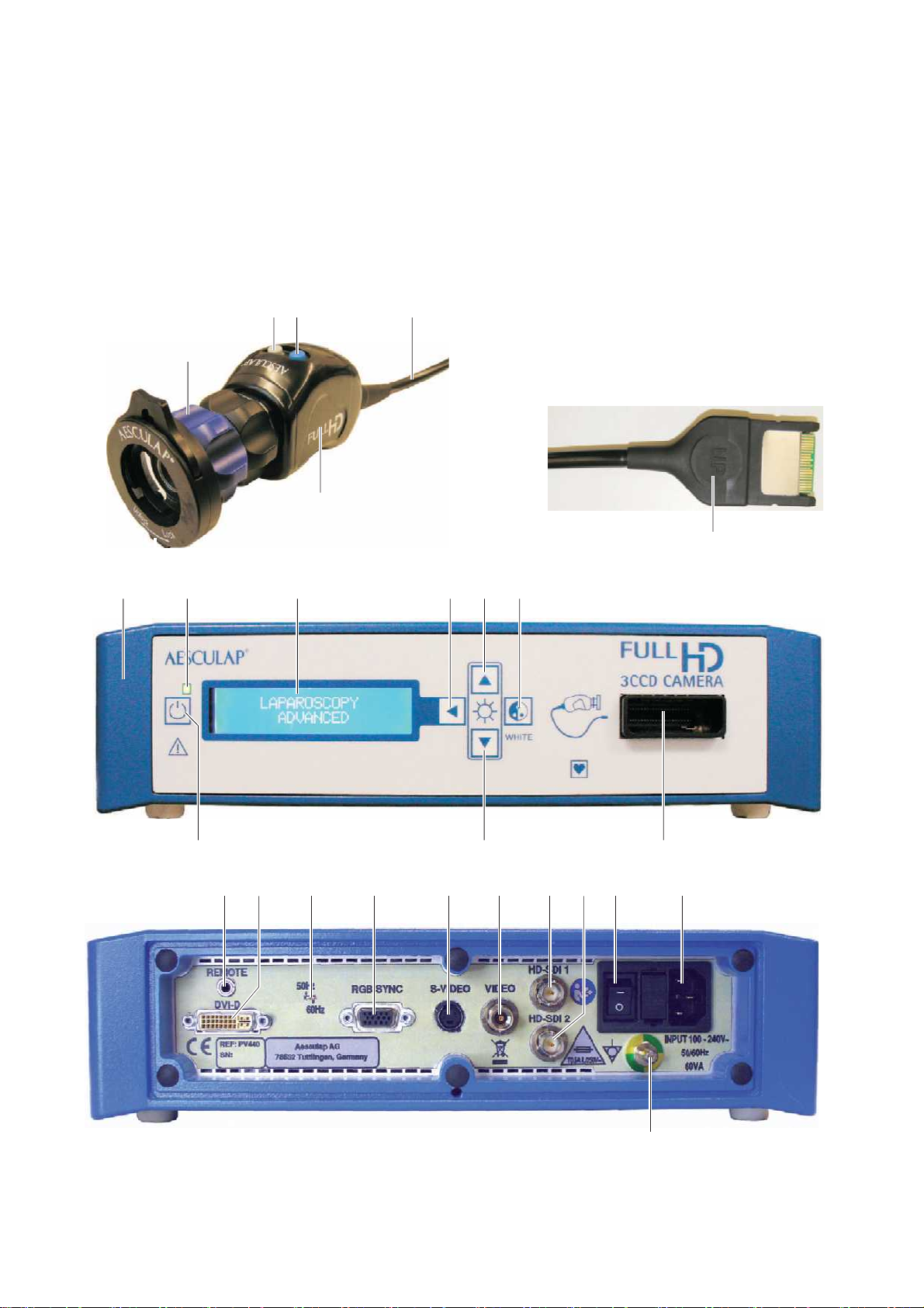
32 4
1
5
87 9 10 11 12
6
131415
16 17 2318 20 21 22 24 25
19
26
Aesculap®
Full HD 3CCD Camera system PV440
Full HD 3CCD Camera system P V440
Legend
®
Aesculap
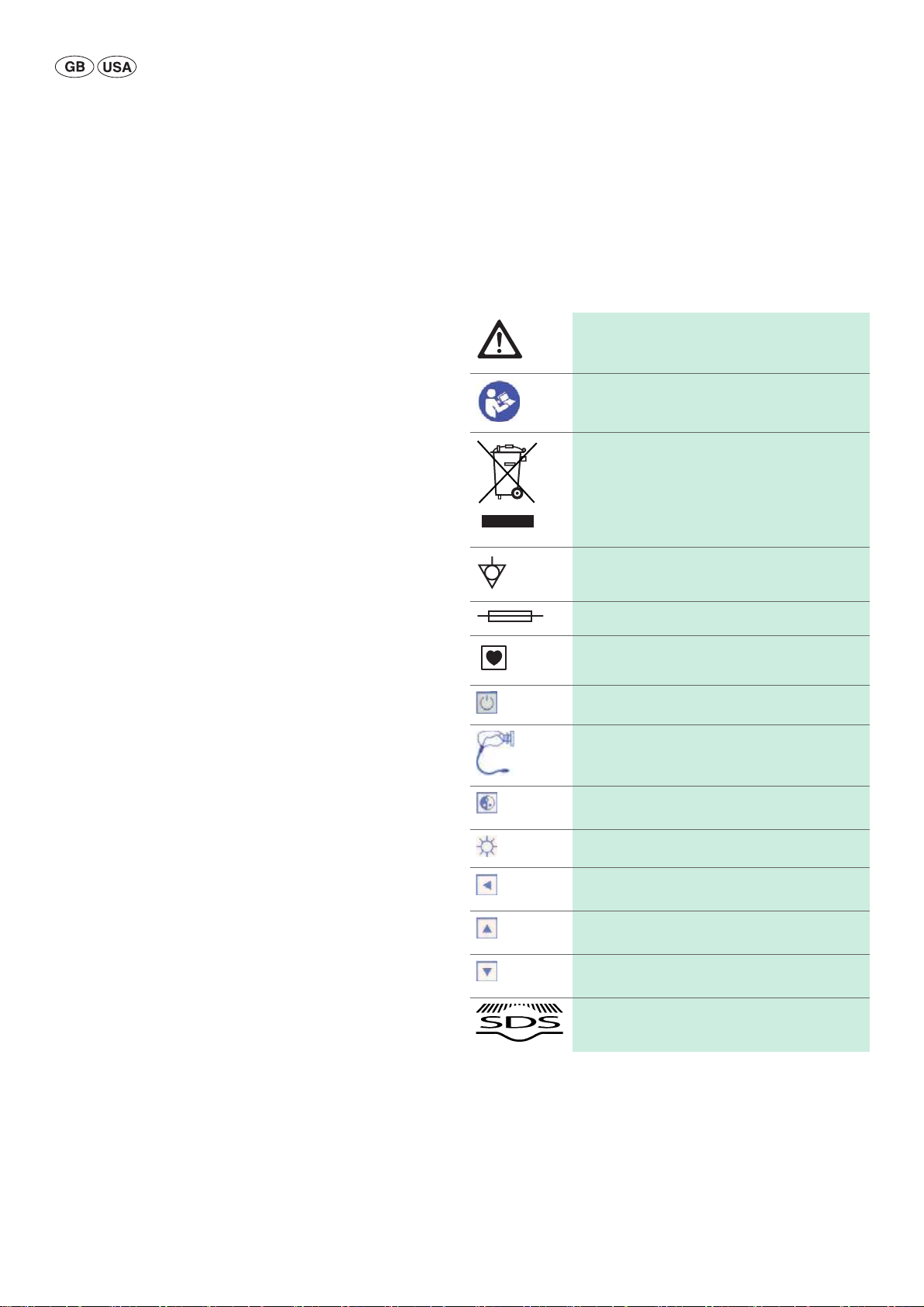
Symbols on product and packages
1 Endo-lens (example image)
2 Gray Push button
3 Blue Push button
4 Camera cable
5 Camera head
6 Camera plug
7 Camera control unit
8 ON/OFF LED
9 Camera display
10 Push button (for mode setting)
11 Push button (for increasing brightness)
12 Push button (for automatic white balance)
13 Camera socket
14 Push button (for decreasing brightness)
15 Push button (ON/STANDBY)
16 Mono jack for remote control (3.5 mm)
17 DVI-D video output (High Definition)
18 50/60 Hz switch (serial number 2000 or higher)
19 RGB video output (High Definition)
20 S-VIDEO output (Standard Definition)
21 VIDEO output (Standard Definition)
22 HD-SDI video output 1 (High Definition)
23 HD-SDI video output 2 (High Definition)
24 ON/OFF switch
25 Mains power
26 Equipotentialization connection
Caution, general warning symbol
Caution, see documentation supplied with the product
Follow the instructions for use
Marking of electric and electronic devices according
to directive 2002/96/EC (WEEE). see Disposal
Equipotentialization connection
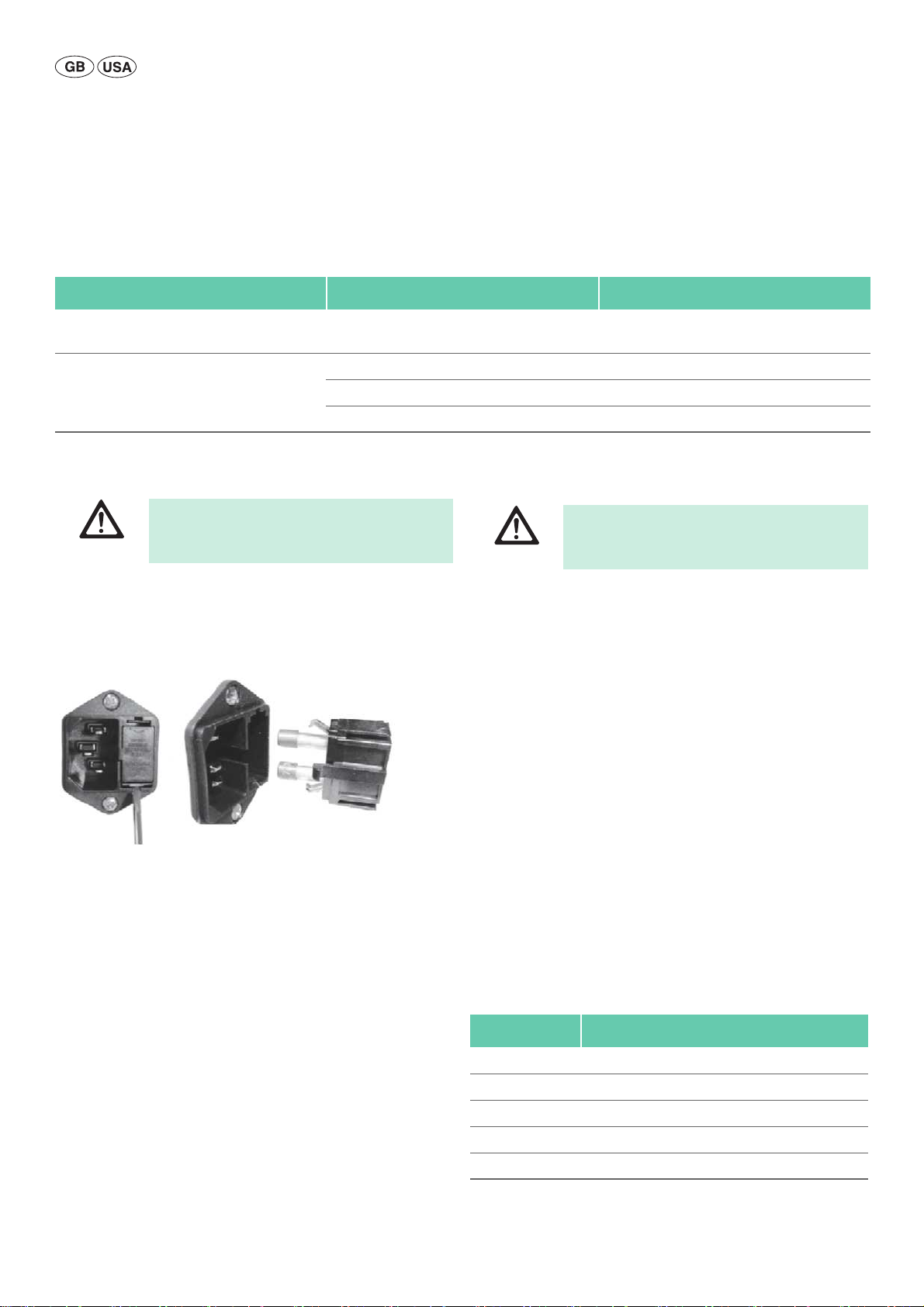
Fuse
Type CF applied part
Power on/standby
Camera socket
Push button for automatic white balance or to set in
the camera menu
Brightness
Push button for mode selection or to close the camera menu
Push button for increasing brightness or to move
"up" in the camera menu
Push button for decreasing brightness or to move
"down" in the camera menu
Low temperature and plasma sterilization
2
Contents
1. Applicable to 3
2. Safe handling 3
3. Product description 4
3.1 Scope of supply 4
3.2 Components required for operation 4
3.3 Intended use 4
3.4 Operating principle 4
4. Preparation and setup 4
4.1 First use 4
Connecting the accessories 5
Presetting the correct voltage 5
Mains power 5
Connecting the video cable 5
Screwing on the endo-lens 6
4.2 Settings 6
Access to main menu 6
Changing video formats 6
Changing the display language 6
Exit main menu 6
5. Working with the Full HD Camera 7
5.1 System set-up 7
5.2 Function checks 7
5.3 Safe operation 7
Connecting the endoscope and sterile cover 7
Performing white balance 7
Selecting the mode 7
Adjusting light, focus and optical zoom 8
Adjusting the digital zoom 8
Adjusting the brightness 8
Adjusting the user mode settings 8
Available parameters for user modes 9
Remote control of an external documentation system 9
6. Validated reprocessing procedure 9
6.1 General safety instructions 9
6.2 General information 9
6.3 Preparations at the place of use 10
6.4 Preparation before cleaning 10
6.5 Cleaning/disinfection 10
Product-specific safety instructions for the reprocessing
procedure 10
Validated cleaning and disinfection procedure 10
6.6 Wipe disinfection for electrical devices without sterilization 11
6.7 Manual cleaning/disinfecting 11
Manual cleaning with immersion disinfection 11
6.8 Inspection, maintenance and checks 12
6.9 Packaging 12
6.10 Sterilization 12
6.11 Storage 12
7. Maintenance 13
8. Troubleshooting list 13
8.1 Fuse replacement 14
9. Technical Service 14
10. Accessories/Spare parts 14
11. Technical data 15
11.1 Ambient conditions 15
12. Disposal 15
13. Distributor in the US/Contact in Canada for product
information and complaints 15
1. Applicable to
► For item-specific instructions for use and information on material
compatibility, see also the Aesculap Extranet at
www.extranet.bbraun.com
2. Safe handling
CAUTION
Federal law restricts this device to sale by or on order of a physician!
Risk of fatal injury from electric shock!
► Do not open the product.
DANGER
WARNING
CAUTION
► Remove the transport packaging and clean the new product, either
manually or mechanically, prior to its initial sterilization.
► Prior to use, check that the product is in good working order.
► Observe “Notes on Electromagnetic Compatibility (EMC)“, see
TA022130.
► Connect the product only to a grounded power
supply.
Risk of injury caused by incorrect operation of the
product!
► Attend appropriate product training before
using the product.
► For information about product training, please
contact your national B. Braun/ Aesculap
agency.
No camera image produced, due to combination of
incompatible components!
► Use the camera head PV442 with serial number
≥ SN3000 only with the camera control unit
PV440 with serial number ≥ SN2000.
3

Aesculap®
Full HD 3CCD Camera system PV440
► To prevent damage caused by improper setup or operation, and in order
not to compromise warranty and manufacturer liability:
– Only use the product according to these instructions for use.
– Follow the safety and maintenance instructions.
– Only combine Aesculap products with each other.
► Ensure that the product and its accessories are operated and used only
by persons with the requisite training, knowledge, or experience.
► Keep the instructions for use accessible for the user.
► Always adhere to applicable standards.
► Do not operate the product in the vicinity of flammable anesthetics.
► Check the power cord for leakage currents and correct grounding at
regular intervals.
3. Product description
3.1 Scope of supply
Full HD 3CCD Camera system PV440, consisting of:
■ Full HD camera control unit
■ Full HD 3CCD Camera head
■ DVI-D cable
■ Instructions for use
3.2 Components required for operation
In addition to the camera system, the following components are required
for an endoscopic intervention:
■ Endo-lens
■ Power cord
■ insert the endoscope
■ Light source
■ Light cable
■ Monitor
3.4 Operating principle
An endoscope visualizes the operation site and an objective lens focuses
this image onto the three CCD sensors, where it is converted into digital
signals. The image brightness is automatically adjusted according to the
light intensity (autoshutter).
Through camera cable 4, the digital image signals are transferred to camera control unit 7, where the digital data are processed to be displayed on
the monitor.
The video signal processed in this way is then picked up at the video output monitor, and digital documentation devices.
The camera system offers automatic, electronic brightness enhancement
for areas that are particularly difficult to illuminate, as well as five different fixed mode settings and three user adjustable mode settings for various situations during operation.
The video camera system is also equipped with a white adjustment system
for optimal color representation.
The lens and an additional electronic zoom feature ensures that the image
on the monitor is displayed at the optimum size.
4. Preparation and setup
Non-compliance with the following instructions will preclude all responsibility and liability in this respect on the part of Aesculap.
► When setting up and operating the product, adhere to
– national regulations for installation and operation,
– national regulations on fire and explosion protection.
Note
For the safety of patients and users it is essential that the mains power cord
and, especially, the protective earth connection are intact. In many cases
defective or missing protective earth connections are not registered immediately.
► Connect the device via the potential equalization terminal at the rear
panel of the device to the potential equalization system of the room
used for medical purposes.
3.3 Intended use
The Aesculap Full HD (=High Definition) camera is an endoscopic video
camera to transmit real-time video images of a rigid or flexible endoscope,
via the use of a lens with endocoupler, to a video monitor or other related
documentation devices.
The Aesculap Full HD camera is suitable for all endoscopic applications.
The current use of the camera involves connecting a lens with endocou-
pler to the camera. An endoscope with standard eyepiece is then connected to the endocoupler and held in place by the grasping mechanism
of the endocoupler.
The Full HD camera is the preferred camera for endoscopic procedures due
to its superior image quality of 1920 x 1080 pixel and progressive scan
mode.
4
Note
The potential equalization lead can be ordered from the manufacturer as
art. no. GK535 (4 m length) or TA008205 (0.8 m length).
4.1 First use
Risk of injury and/or product malfunction due to
incorrect operation of the electromedical system!
WARNING
► Adhere to the instructions for use of any medi-
cal device.

4.1.1 Connecting the accessories
Risk of injury due to unapproved configuration
using additional components!
DANGER
Combinations of accessories that are not mentioned in the present
instructions for use may only be employed if they are specifically intended
for the respective application, and if they do not compromise the performance and safety characteristics of the products.
Also note that any equipment connected at the interfaces must demonstrably meet the respective IEC standards (e.g. IEC 60950 for data processing equipment, IEC/DIN EN 60601-1 for electromedical devices).
All configurations must comply with basic standard IEC/DIN EN 60601-1.
Any individual connecting devices with one another is responsible for such
configuration and must ensure compliance with basic standard IEC/DIN
EN 60601-1 or applicable national standards.
► Please address your B. Braun/Aesculap partner or Aesculap Technical
Service with any inquiries in this respect; for a contact address, see
Technical Service.
4.1.2 Presetting the correct voltage
The mains voltage must correspond to the voltage indicated on the type
plate at the back of the unit.
4.1.3 Mains power
WARNING
► Plug in the power cord at mains connection 25 of camera control
unit 7.
► Connect the mains plug of the power cord to the building mains.
► Plug in the equipotentialization cable at equipotentialization connec-
tor 26 of camera control unit.
► Connect the plug of the equipotentialization cable to the building
mains equipotentialization connector.
► To disconnect the camera from the mains pull out the power cord from
the mains connection 25.
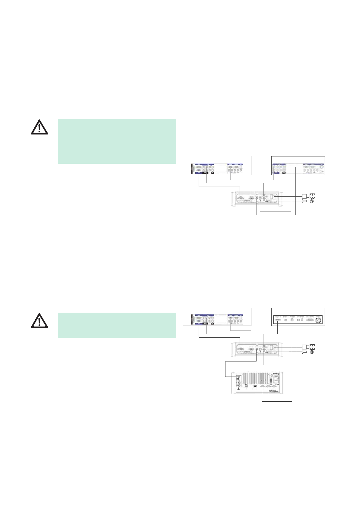
4.1.4 Connecting the video cable
► Connect the video cable to the camera rear panel and to the monitor,
documentation systems etc. Depending on the monitor and documentation system use the following connections:
► For all applied components, ensure that their
classification matches that of the application
component (e.g. Type BF or Type CF) of the
respective device.
Risk of electric shock!
► Only connect the equipment to a supply mains
with protective earth.
HD Monitor (High Definition):
■ DVI-D for digital HD 1080p quality
- or -
■ HD-SDI for digital HD 1080i/720p quality
- or -
■ RGB-Sync for analog HD 1080i/720p quality
12
4
3
5
Fig. 1
Legend
1 HD Monitor
2 SD Monitor
3 Full HD camera system
4 Mains
5 Equipotentialization
SD Monitor/SD documentation system (Standard Definition):
■ S-Video for analog SD quality
- or -
■ Video for analog SD quality
12
4
5
3
6
Fig. 2
Legend
1 HD Monitor
2 SD Monitor
3 Full HD camera system
4 Mains
5 Equipotentialization
6 e.g. Aesculap Eddy DVD
5
Aesculap®
Full HD 3CCD Camera system PV440
4.1.5 Screwing on the endo-lens
Note
Different endo-lenses are available for the camera system.
► Follow instructions for use of the endo-lens.
► Screw endo-lens 1 onto camera head 5.
4.2 Settings
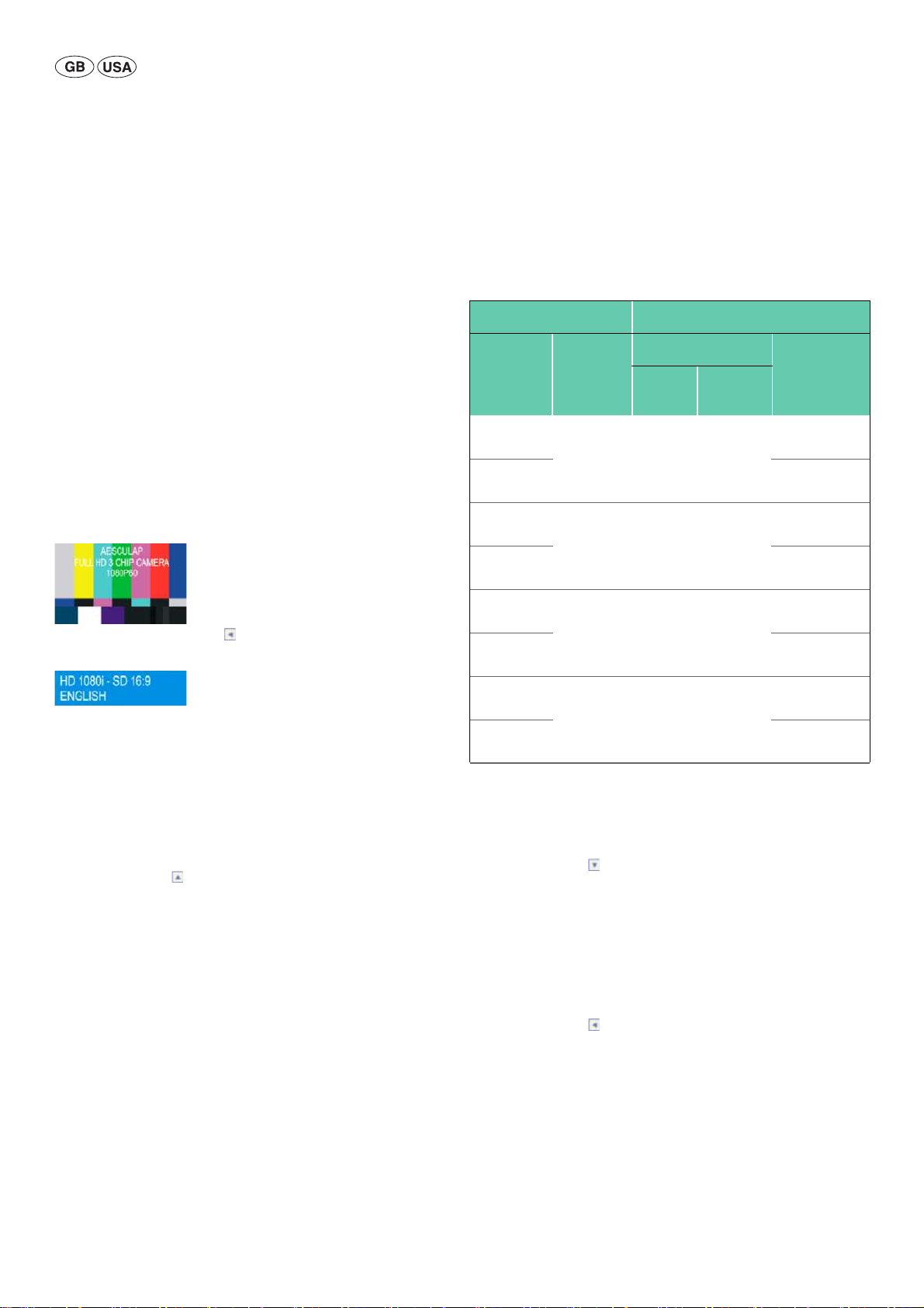
4.2.1 Access to main menu
► Unplug the camera plug 6 from the camera socket 13.
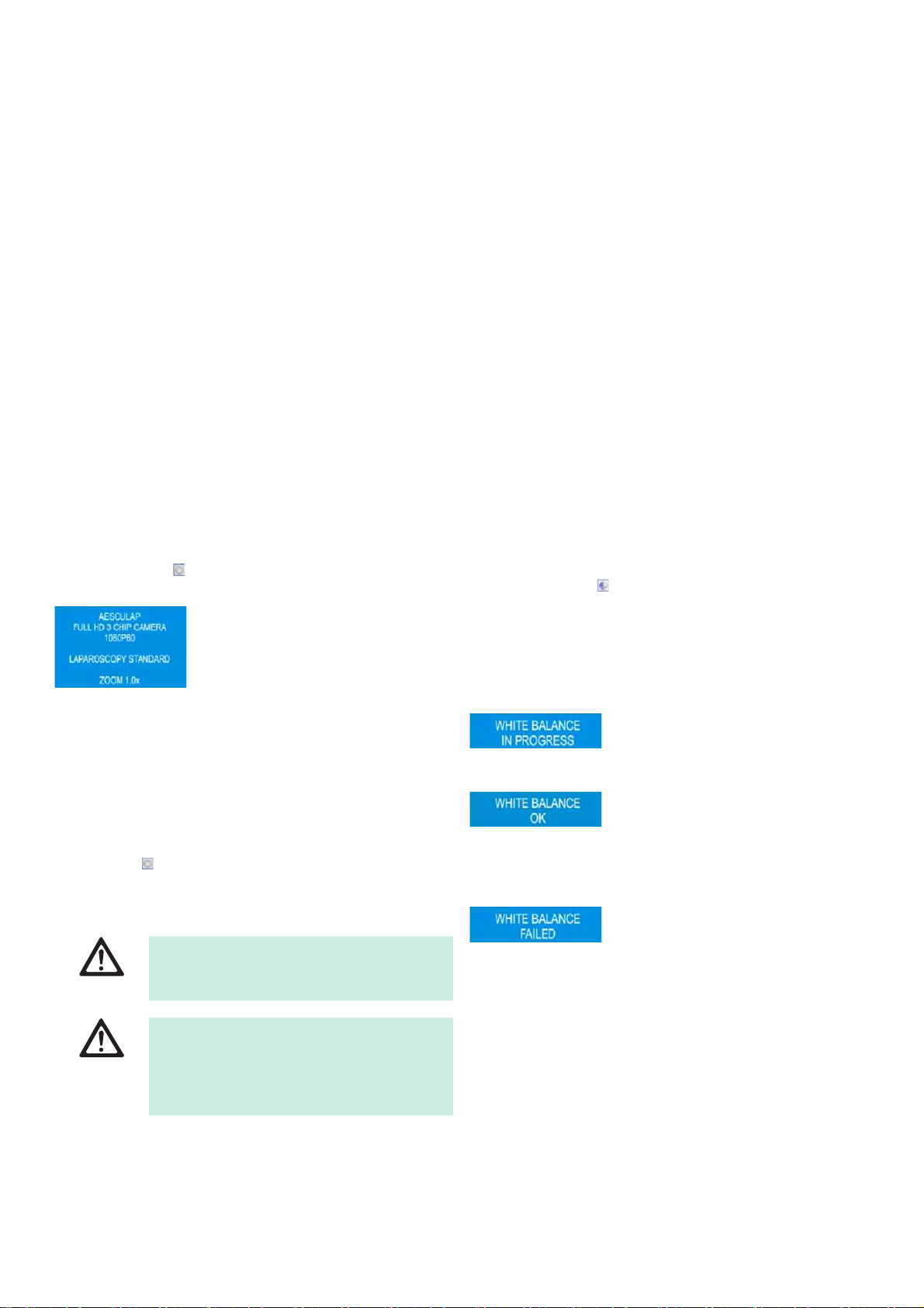
► Switch on camera control unit 7.
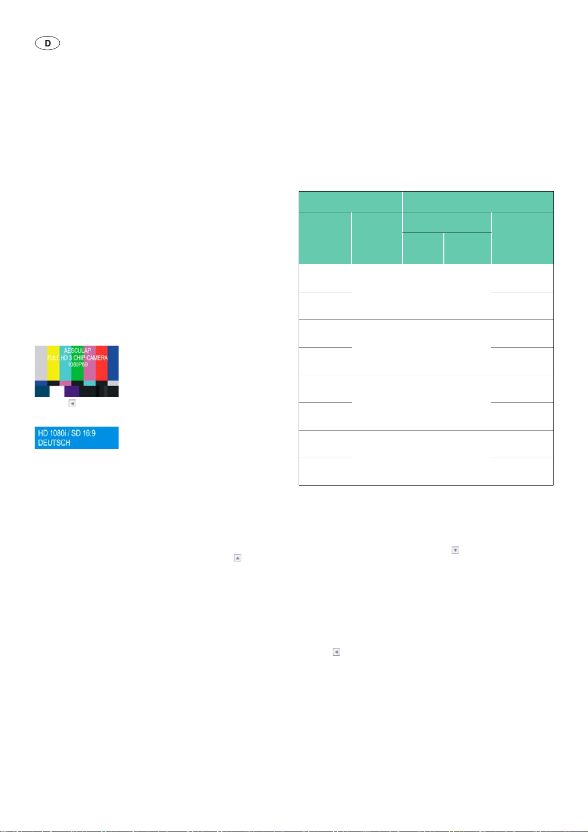
The following test chart appears on the monitor:
► Press and hold Push button 10 for 3 seconds.
The following message appears on the camera display:
4.2.2 Changing video formats
Note
If the aspect ratio is set to 4:3, the image is cut off on the left and right margins with SD video signals.
► Select the camera frequency 50 Hz or 60 Hz (serial number 2000 and
higher): Put 50/60 Hz switch 18 in the corresponding position, according to your requirements.
► Press Push button 11 in the main menu to change the video format.
The following formats can be set:
Camera setting Video outputs
Main menu 50/60 Hz
switch
HD 1080i–
SD 16:9
HD 1080i–
SD 4:3
HD 720p–
SD 16:9
HD 720p–
SD 4:3
HD 1080i–
SD 16:9
HD 1080i–
SD 4:3
HD 720p–
SD 16:9
HD 720p–
SD 4:3
* There is always a progressive scan signal on the DVI-D output.
4.2.3 Changing the display language
► Press Push button 14 to change the display language.
– English
–Deutsch
–Français
–Español
–Italiano
50 Hz 1080p 50 1080i 50 576i PAL 16:9
50 Hz 720p 50 720p 50 576i PAL 16:9
60 Hz 1080p 60 1080i 60 480i NTSC 16:9
60 Hz 720p 60 720p 60 480i NTSC 16:9
Aspect ratio 16:9 S-Video/Video
DVI-D* HD-SDI/
RGB
576i PAL 4:3
576i PAL 4:3
480i NTSC 4:3
480i NTSC 4:3
4.2.4 Exit main menu
► Press Push button 10 or plug in camera plug 6.
6
5. Working with the Full HD Camera
5.1 System set-up
► Position the camera tower as close as possible to the patient so that
the camera cable length of 3 m can be fully utilized.
► Connect the camera plug 6 to camera socket 13 at the front panel of
camera control unit 7. Take care that the marking UP on the camera
plug 6 is pointing upwards.
5.2 Function checks
► Check camera control unit 7 and the camera head 5 for external dam-
age and signs of knocks or other violent impacts.
► Check that the camera cable 4 is not broken, kinked or twisted.
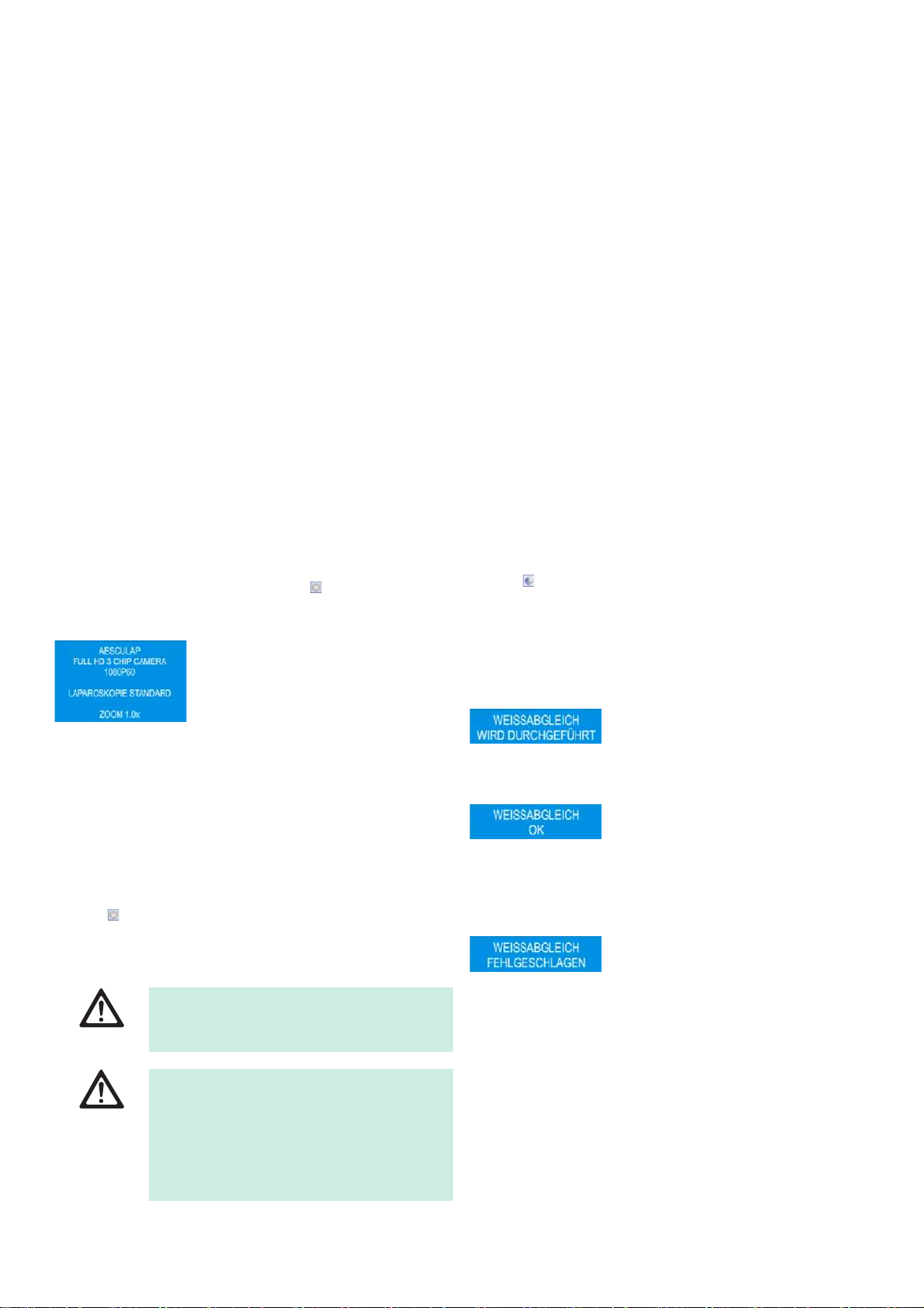
► Press Push button 15 to power on the camera system.
The current settings of the camera appear on the monitor:
► Check to make certain that the front window of endo-lens 1 is com-
pletely clean. If necessary, clean the window with isopropyl alcohol
(70 %).
► If necessary, ensure that the zoom adjustment ring turns freely without
resistance.
► Make certain that the focusing ring turns freely without resistance.
► Align camera head 5 to an object in the room, focus the image and
check for good image quality.
► To terminate the operation of the Full HD camera system press the
Push button 15.
5.3 Safe operation
5.3.1 Connecting the endoscope and sterile cover
► Make certain that the locking slide is opened ("Unlock" position).
► Press and hold down lock.
► Insert sterile endoscope with sterile cover and release lock.
► To lock the endoscope against rotation, close the locking slide ("lock"
position).
► Cover the camera head and cable with the sterile cover fixed to the
sterile endoscope.
Note
The endocoupler can be positioned as required. To do this, swivel endocoupler to the required position!
5.3.2 Performing white balance
► Point endoscope to a white object (for example a sterile swab) at a dis-
tance of 2 cm.
► Press Push button 12 on the control unit and keep endoscope
pointed at the white object.
- or -
► Press gray Push button 2 on the camera head for longer than 2.5 sec-
onds and keep endoscope pointed at the white object.
The following message appears on the camera display and on the mon-
itor:
► If the white balance is performed properly, the following message
appears on the camera display and on the monitor:
The image will be displayed in pure white. This procedure ensures the
accurate representation of all colors.
► If the white balance did not perform properly, the following message
appears on the camera display and on the monitor:
WARNING
DANGER
Risk of injury and/or malfunction!
► Always carry out a function check prior to using
the product.
Risk of injury due to unapproved configuration!
► Make certain that application parts of other
electrical medical devices or accessories used in
this configuration for the endoscopic application are of type BF or CF.
► In this case please repeat the white balance procedure.
5.3.3 Selecting the mode
To achieve the optimum image quality with endoscopes for different surgical applications, the following modes can be selected:
■ Laparoscopy Standard
■ Laparoscopy Advanced
■ Arthroscopy
■ Hysteroscopy
■ Neuroendoscopy
■ User 1
■ User 2
■ User 3
7
Aesculap®
Full HD 3CCD Camera system PV440
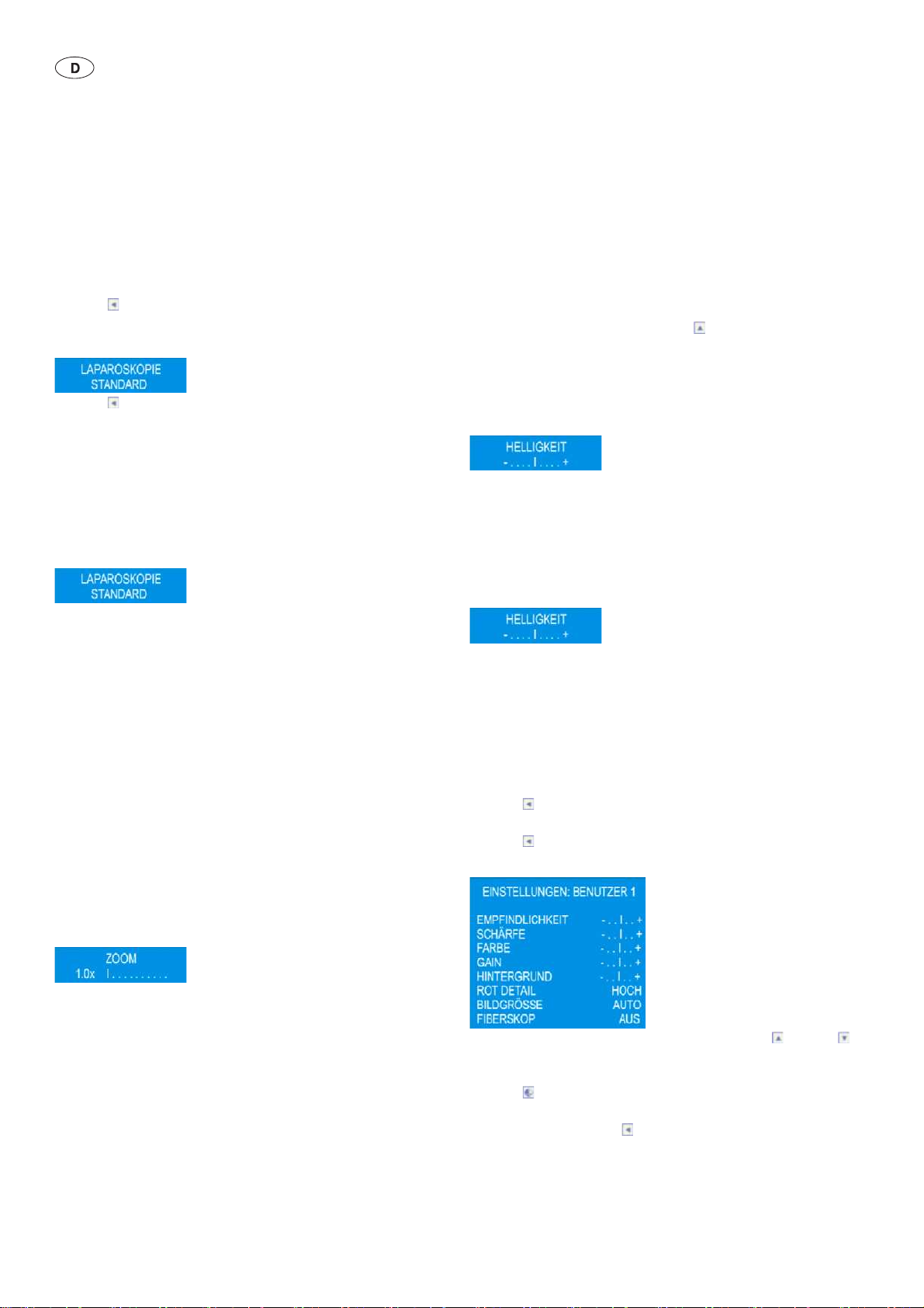
To change the mode on the camera control unit:
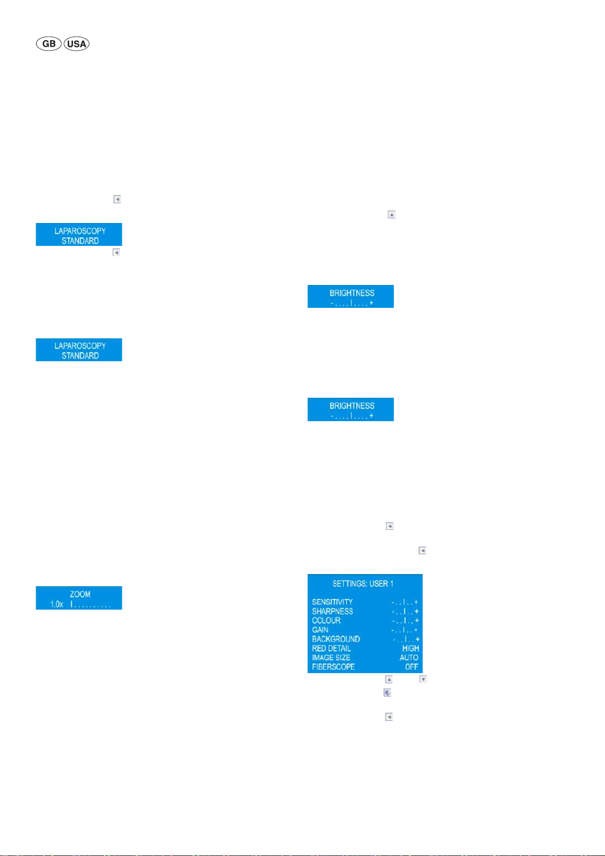
► Press Push button 10 on camera control unit once.
The current mode appears on the camera display and on the monitor:
► Press Push button 10 on camera control unit until the desired mode
is displayed.
After 3 seconds the setting displayed will disappear and the selected
mode is saved.
To change the mode on the camera head:
► Press both Push buttons on the camera head for longer than 3 seconds.
The current mode appears on the camera display and on the monitor:
► Press the blue Push button on the camera head to switch to previous
mode or press the gray Push button on the camera head to switch to
next mode.
After 3 seconds the setting displayed will disappear and the selected
mode is saved.
5.3.4 Adjusting light, focus and optical zoom
► Adjust the brightness of the light source until sufficient illumination is
achieved.
► To adjust the focus for a sharp image, turn focusing ring.
► To adjust the size of the image (zoom factor), turn the zoom adjust-
ment ring.
5.3.5 Adjusting the digital zoom
► Press both Push buttons on the camera head and release both after a
short time (2.5 seconds).
The following message appears on the camera display and on the mon-
itor:
5.3.6 Adjusting the brightness
To adjust the brightness on the camera control unit:
► Press Push button 11 on the camera control unit to increase the
brightness.
► Press Push button 14 on the camera control unit to decrease the
brightness.
The following message appears on the camera display and on the mon-
itor:
After 3 seconds the setting displayed will disappear and the selected
brightness setting is saved.
To adjust the brightness on camera head:
► Press gray Push button 2 on the camera head and release after a short
time (2.5 seconds).
The following message appears on the camera display and on the mon-
itor:
► To change the brightness, press one of the Push buttons on the camera
head as follows:
– press the blue Push button 3 to decrease the brightness.
– press the gray Push button 2 to increase the brightness. After 3 sec-
onds the setting displayed will disappear and the selected brightness setting is saved.
5.3.7 Adjusting the user mode settings
► Press Push button 10 on camera control unit 7 and select USER 1,
USER 2 or USER 3 mode.
► Press and hold Push button 10 for 3 seconds.
The following message appears on the monitor:
The following digital zoom settings can be selected:
■ Zoom switched off = ZOOM 1.0
■ Zoom activated = ZOOM 1.1x /1.2x /1.3x /1.4x /1.5x/1.6x /1.7x /1.8x/
1.9x/2.0x
► To change the digital zoom setting, press one of the Push buttons on
the camera head as follows:
– press the blue Push button to decrease the digital zoom.
– press the gray Push button to increase the digital zoom. After 3 sec-
onds the setting displayed will disappear and the selected zoom
setting is saved.
8
► Press Push button 11 or 14 to select the desired parameter.
► Press Push button 12 to change the setting of the respective param-
eter.
► Press Push button 10 to save and exit user settings.
- or After 40 seconds the setting options displayed will disappear and the
selected settings are saved.

5.3.8 Available parameters for user modes
■ Sensitivity: This parameter changes the brightness control. A low value
(-) causes the camera to reduce the brightness if there is a small bright
object. A high value (+) causes the camera to reduce the brightness if
the average of the complete image is too bright
■ Focus: This parameter decreases (-) or increases (+) the digital detail
enhancement.
■ Color: This parameter decreases (-) or increases (+) the color satura-
tion.
■ Gain: This parameter decreases (-) or increases (+) the maximum value
of the dynamic gain. The camera reduces the dynamic gain automatically if there is enough light in the image.
■ Background: This parameter decreases (-) or increases (+) the bright-
ness of dark backgrounds.
■ Red detail: This parameter decreases (OFF) or increases (LOW, HIGH)
the digital enhancement especially for fine red details.
■ Image size: This parameter defines the image size for the brightness
measurement area. Settings are AUTO, LARGE, MEDIUM, SMALL.
■ Fiberscope: The setting ON will deactivate the digital detail enhance-
ment to minimize the moiré effect for fiberoptical endoscopes.
5.3.9 Remote control of an external documentation system
To connect an external documentation system (e.g. Aesculap Eddy DVD or
any other suitable documentation system) to the mono jack for remote
control 16 labeled REMOTE:
► Connect remote control cable PV968 between the camera and the doc-
umentation system.
► For remote-controlling the external documentation system, press blue
Push button 3 on camera head 5.
6. Validated reprocessing procedure
6.1 General safety instructions
Note
Adhere to national statutory regulations, national and international standards and directives, and local, clinical hygiene instructions for sterile processing.
Note
For patients with Creutzfeldt-Jakob disease (CJD), suspected CJD or possible variants of CJD, observe the relevant national regulations concerning
the reprocessing of products.
Note
Mechanical reprocessing should be favored over manual cleaning as it
gives better and more reliable results.
Note
Successful processing of this medical device can only be ensured if the processing method is first validated. The operator/sterile processing technician is responsible for this.
The recommended chemistry was used for validation.
Note
If there is no final sterilization, then a virucidal disinfectant must be used.
Note
For the latest information on reprocessing and material compatibility see
also the Aesculap extranet at www.extranet.bbraun.com
The validated steam sterilization procedure was carried out in the Aesculap
sterile container system.
6.2 General information
Dried or affixed surgical residues can make cleaning more difficult or ineffective and lead to corrosion. Therefore the time interval between application and processing should not exceed 6 h; also, neither fixating precleaning temperatures >45 °C nor fixating disinfecting agents (active
ingredient: aldehydes/alcohols) should be used.
Excessive measures of neutralizing agents or basic cleaners may result in
a chemical attack and/or to fading and the laser marking becoming
unreadable visually or by machine for stainless steel.
Residues containing chlorine or chlorides e.g. in surgical residues, medicines, saline solutions and in the service water used for cleaning, disinfection and sterilization will cause corrosion damage (pitting, stress corrosion) and result in the destruction of stainless steel products. These must
be removed by rinsing thoroughly with demineralized water and then drying.
Additional drying, if necessary.
Only process chemicals that have been tested and approved (e.g. VAH or
FDA approval or CE mark) and which are compatible with the product’s
materials according to the chemical manufacturers’ recommendations
may be used for processing the product. All the chemical manufacturer's
application specifications must be strictly observed. Failure to do so can
result in the following problems:
■ Optical changes of materials, e.g. fading or discoloration of titanium or
aluminum. For aluminum, the application/process solution only needs
to be of pH >8 to cause visible surface changes.
■ Material damage such as corrosion, cracks, fracturing, premature aging
or swelling.
► Do not use metal cleaning brushes or other abrasives that would dam-
age the product surfaces and could cause corrosion.
► Further detailed advice on hygienically safe and material-/value-pre-
serving reprocessing can be found at www.a-k-i.org, link to Publications, Red Brochure – Proper maintenance of instruments.
9
Aesculap®
Full HD 3CCD Camera system PV440
6.3 Preparations at the place of use
► Remove any visible surgical residues to the extent possible with a
damp, lint-free cloth.
► Transport the dry product in a sealed waste container for cleaning and
disinfection within 6 hours.
6.4 Preparation before cleaning
Camera head
► Reprocess the product immediately after use.
► Use suitable cleaning/disinfecting agents if the product is put away in
a wet condition.
Damage to the product due to improper handling
when reprocessing!
CAUTION
► Separate the camera head from the camera
control unit prior to reprocessing.
► Reprocess the camera head and the camera con-
trol unit separately.
6.5 Cleaning/disinfection
6.5.1 Product-specific safety instructions for the reprocessing procedure
CAUTION
CAUTION
CAUTION
Damage to, or destruction of the product caused by
mechanical cleaning/disinfection!
► Only clean and disinfect the product manually.
Damage to the product due to inappropriate cleaning/disinfecting agents!
► Only use cleaning/disinfecting agents approved
for surface cleaning. Follow the manufacturer’s
instructions for the respective cleaning/disinfecting agent.
Damage to the product due to inappropriate cleaning/disinfecting agents and/or excessive temperatures!
► Use cleaning and disinfecting agents according
to the manufacturer’s instructions which
– Ensure that cleaning and disinfecting agents
are approved for use on anodized aluminum,
plastics (PPSU) and stainless steel.
– do not attack softeners (e.g. in silicone).
► Observe specifications regarding concentration,
temperature and exposure time.
► Do not exceed the maximum allowable temper-
ature of 60 °C.
Risk of electric shock and fire hazard!
► Unplug the device before cleaning.
DANGER
6.5.2 Validated cleaning and disinfection procedure
Validated procedure Special features Reference
Wipe disinfection for
electrical devices without sterilization
► Do not use flammable or explosive cleaning or
disinfecting solutions.
► Ensure that no fluids will penetrate the product.
– Chapter Wipe disinfection for electrical devices
without sterilization
■ Camera control unit
Manual cleaning with
immersion disinfection
■ Camera head
■ Suitable cleaning brush
■ 20 ml disposable syringe
■ When cleaning products with movable hinges, ensure that these are
in an open position and, if applicable, move the joint while cleaning.
Chapter Manual cleaning/disinfecting and subsection:
■ Chapter Manual cleaning with immersion
disinfection
■ Drying phase: Use a lint-free cloth or medical compressed air
(p
=5 bar)
max
10

6.6 Wipe disinfection for electrical devices without sterilization
Phase Step T
[°C/°F]t[min]
Conc.
[%]
Water quality Chemical
IWipe disinfectionRT ≥1 - - Meliseptol HBV wipes 50 % Propan-1-ol
RT: Room temperature
Phase I
► Remove any visible residues with a disposable disinfectant wipe.
► Wipe all surfaces of the optically clean product with a fresh, disposable
disinfectant wipe.
► Observe the specified application time (1 min minimum).
6.7 Manual cleaning/disinfecting
► Prior to manual disinfecting, allow water to drip off for a sufficient
length of time to prevent dilution of the disinfecting solution.
► After manual cleaning/disinfection, check visible surfaces visually for
residues.
► Repeat the cleaning/disinfection process if necessary.
6.7.1 Manual cleaning with immersion disinfection
Phase Step T
[°C/°F]t[min]
Conc.
[%]
Water
quality
Chemical
I Disinfecting cleaning RT (cold) >15 2 D–W Aldehyde-free, phenol-free, and QUAT-free concentrate, pH ~ 9*
II Intermediate rinse RT (cold) 1 - D–W -
III Disinfection RT (cold) 15 2 D–W Aldehyde-free, phenol-free, and QUAT-free concentrate, pH ~ 9*
IV Final rinse RT (cold) 1 - FD-W -
VDrying RT - - - -
D–W: Drinking water
FD–W: Fully desalinated water (demineralized, low microbiological contamination: drinking water quality at least)
RT: Room temperature
*Recommended: BBraun Stabimed
► Note the information on appropriate cleaning brushes and disposable
syringes, see Validated cleaning and disinfection procedure.
11
Aesculap®
Full HD 3CCD Camera system PV440
Phase I
► Fully immerse the product in the cleaning/disinfectant for at least 15
min. Ensure that all accessible surfaces are moistened.
► Clean the product with a suitable cleaning brush in the solution until
all discernible residues have been removed from the surface.
► If applicable, brush through non-visible surfaces with an appropriate
cleaning brush for at least 1 min.
► Mobilize non-rigid components, such as set screws, links, etc. during
cleaning.
► Thoroughly rinse through these components with the cleaning disin-
fectant solution (at least five times), using a disposable syringe.
Phase II
► Rinse/flush the product thoroughly (all accessible surfaces) under run-
ning water.
► Mobilize non-rigid components, such as set screws, joints, etc. during
rinsing.
► Drain any remaining water fully.
Phase III
► Fully immerse the product in the disinfectant solution.
► Mobilize non-rigid components, such as set screws, joints, etc. during
rinsing.
► Rinse lumens at least 5 times at the beginning of the exposure time
using an appropriate disposable syringe. Ensure that all accessible surfaces are moistened.
Phase IV
► Rinse/flush the product thoroughly (all accessible surfaces).
► Mobilize non-rigid components, such as set screws, joints, etc. during
final rinse.
► Rinse lumens with an appropriate disposable syringe at least five times.
► Drain any remaining water fully.
Phase V
► Dry the product in the drying phase with suitable equipment (e.g. cloth,
compressed air), see Validated cleaning and disinfection procedure.
6.8 Inspection, maintenance and checks
► Allow the product to cool down to room temperature.
► Inspect the product after each cleaning and disinfecting cycle to be
sure it is: clean, functional, and undamaged.
► Check the product for any damage, abnormal running noise, overheat-
ing or excessive vibration.
► Set aside the product if it is damaged.
► Remove the moisture from the camera plug and check that the con-
tacts are dry.
6.9 Packaging
► Follow the instructions for use for the applied packaging and storage
systems (e.g. instructions for use TA009721 for Aesculap Eccos storage
system).
► Insert the product in its proper position in the Eccos holder, or put it
on a tray in such a way that the product is protected against damage.
Ensure that all cutting edges are protected.
► Pack trays appropriately for the sterilization process (e.g. in Aesculap
sterile containers).
► Ensure that the packaging will prevent a recontamination of the prod-
uct.
6.10 Sterilization
Damage to the camera control unit by sterilization!
► Do not sterilize the camera control unit under
CAUTION
any circumstances.
► Clean the camera control unit by surface disin-
fection only.
Damage to the camera head or the optical zoom
coupler caused by inappropriate sterilization pro-
CAUTION
cesses!
► Never sterilize the camera head or the optical
zoom coupler with steam or in an autoclave.
► Do not carry out chemical sterilization.
Working with disposable sterile covers
► Use suitable Aesculap disposable sterile covers. Follow the instructions
for use of the sterile covers.
Sterilization with Sterrad® 50, 100, 100S, 200 sterilization process
Note
The Sterrad® sterilization process can cause cosmetic changes to the camera head and cable. These changes, however, do not affect its functionality.
► Sterilize by the Sterrad® sterilization process 50, 100,100S or 200,
observing the following rules: Follow the manufacturer’s instructions
for use of the Sterrad® system. Use of a biological indicator is recommended to confirm effective sterilization.
6.11 Storage
► Store sterile products in germ-proof packaging, protected from dust, in
a dry, dark, temperature-controlled area.
12

7. Maintenance
To ensure reliable operation, the product must be maintained at least once a year.
For technical service, please contact your national B. Braun/Aesculap agency, see Technical Service.
8. Troubleshooting list
Malfunction Cause Remedy
No image on the monitor Device not powered Verify that all units are connected to mains con-
nector and switched on
Fuse blown Replace camera fuse T0.5 A L/250 V~
(TA020394)
Wrong video input activated If the monitor supports several channels: Make
certain the monitor is switched to the channel
that is connected to the camera system
Video cable defective Replace video cable
Video cable not connected Connect video cable
Image too dark Camera cable not connected or defective Ensure that the camera head is connected to the
camera control unit and the camera plug is dry
Light cable not connected Verify that the light cable is connected at the
light source and the light cable input of the
endoscope
Light cable defective Connect a new light cable/Have repaired by
manufacturer
Light source dimmed down Turn up the light source intensity
Endoscope optical system defective If the image is too dark even without the cam-
era: Use a different endoscope and have the
defective endoscope repaired by the manufacturer
Image fuzzy or poorly defined Object out of focus Turn the focus adjustment setting ring of the
zoom coupler until there is a sharp image
Debris on the endoscope tip Clean tip with a sterile cloth and isopropyl alco-
hol (70 %)
Moisture on the camera cable plug Dry plug with gauze before plugging it in at the
camera plug
Image fogged Contaminated or fogged endoscope Check if the front and rear windows of the
endoscope and the front window of the zoom
coupler are clean; if necessary, clean with isopropyl alcohol (70 %)
Use Aesculap Anti Fog Solution JG910 on the
window on the distal end of the endoscope
Noise or excessive grain in the picture Brightness enhancement function is active Increase intensity of the light source
Image too bright or glary Light metering not at its optimum setting Press Push button 10 for the mode selection and
select the optimum light metering mode
13
Aesculap®
Full HD 3CCD Camera system PV440
Malfunction Cause Remedy
Color bar displayed on the monitor Camera cable not connected to the camera con-
trol unit
Inaccurate color representation on the monitor White balance failed Initiate white-adjustment
Inappropriate monitor color settings Reset to factory setting
Video cable defective Replace video cable
8.1 Fuse replacement
Risk of fatal injury from electric shock!
► Unplug the device before changing the fuses!
DANGER
Specified fuses: T 0.5 A L/250 V~; Art. no. TA020394
► Use a small screwdriver to release the clip on the fuse holder.
► Pull out the fuse holder.
► Replace both fuses.
► Reinsert the fuse holder in such a way that it audibly snaps into place.
Fig. 3 Fuse replacement
Note
If the fuses burn out frequently, the device is faulty and should be
repaired, see Technical Service.
9. Technical Service
WARNING
► For service and repairs, please contact your national B. Braun/
Aesculapagency.
Modifications carried out on medical technical equipment may result in
loss of guarantee/warranty rights and forfeiture of applicable licenses.
Service addresses
Repairs handling camera systems:
Aesculap FLEXIMED GmbH
Repair Service
Robert-Bosch-Str. 1
79211 Denzlingen/Germany
Phone: +49 7666 93 21 0
Fax: +49 7666 93 21 580
E-mail: techserv@aesculap-fleximed.de
Telephone hotline for technical assistance with electrical devices and
device combinations:
Phone: +49 7461 95 1601
Other service addresses can be obtained from the address indicated above.
Connect camera cable at the camera control
unit
Risk of injury and/or malfunction!
► Do not modify the product.
14
10. Accessories/Spare parts
Art. no. Designation
PV442 Camera head and camera cable
PV441 Camera cable
PV126S Endo-lens with zoom
PV127S Fixed focal length endo-lens
TA020394 Fuse set T 0.5 A L/250 V~
11. Technical data
11.1 Ambient conditions
Classification acc. to Directive 93/42/EEC
Art.
no.
PV442 Camera head and camera cable I
PV440 Camera control unit
Art. no. Designation
Mains power 100-240 V AC, 50 Hz to 60 Hz
Power consumption 45 VA
Image sensors 3 CCD sensor 1/3 Inch
Resolution 1920 x 1080 Pixel
Electronic Zoom 1.0x to 2.0x
Video outputs:
DVI-D
HD-SDI
RGB
S-Video
Video
Protection class
(acc. to IEC/DIN
EN 60601-1)
Dimensions of control
unit (L x W x H)
Dimensions of camera
head (without zoom
lens) (L x W x H)
Applied part Type CF
EMC IEC/DIN EN 60601-1-2
Conforming to standard
Designation Class
1080p or 720p*; 50 Hz or 60 Hz**
Aspect ratio 16:9
1080i or 720p*; 50 Hz or 60 Hz**
Aspect ratio 16:9
1080i or 720p*; 50 Hz or 60 Hz**
Aspect ratio 16:9
PAL or NTSC**
Aspect ratio 16:9 or 4:3*
PAL or NTSC**
Aspect ratio 16:9 or 4:3*
Camera head IPX7
Control unit IP20
305 mm x 75 mm x 305 mm
40 mm x 53 mm x 72 mm
IEC/DIN EN 60601-1
Operation Storage and transport
Temperature +10 °C to +40 °C -20 °C to +60 °C
Relative
humidity
0 % to 90 % (at +20 °C)
or
0 % to 50 % (at +40 °C),
non-condensing
0 % to 90 % (at +20 °C)
or
0 % to 50 % (at +40 °C),
non-condensing
12. Disposal
Note
The user institution is obliged to process the product before its disposal, see
Validated reprocessing procedure.
Adhere to national regulations when disposing of or recycling the product, its components and its packaging!
The recycling pass can be downloaded from the Extranet
as a PDF document under the respective article number.
(The recycling pass includes disassembling instructions for
the product, as well as information for proper disposal of
components harmful to the environment.)
Products carrying this symbol are subject to separate collection of electrical and electronic devices. Within the
European Union, disposal is taken care of by the manufacturer as a free-of-charge service.
► Detailed information concerning the disposal of the product is avail-
able through your national B. Braun/Aesculap agency, see Technical
Service.
13. Distributor in the US/Contact in Canada for product information and complaints
3773 Corporate Parkway
Center Valley, PA, 18034,
USA
* Video format configurable in the main menu, see
Changing video formats
** 50 Hz/60 Hz or PAL/NTSC are switchable on the rear
panel of the device from series number 2000 and higher
15

Aesculap®
Full HD 3CCD Kamerasystem PV440
Full HD 3CCD Kamerasystem P V440
Legende
®
Aesculap
Symbole an Produkt und Verpackung
1 Endo-Objektiv (Bild beispielhaft)
2 Grauer Knopf
3 Blauer Knopf
4 Kamerakabel
5 Kamerakopf
6 Kamerastecker
7 Kamerakontrolleinheit
8 EIN/AUS-LED
9 Kameradisplay
10 Taste (zur Moduseinstellung)
11 Taste (zur Erhöhung der Helligkeit)
12 Taste (für den automatischen Weißabgleich)
13 Kamerabuchse
14 Taste (zur Verringerung der Helligkeit)
15 Taste (EIN/STANDBY)
16 Monobuchse für Fernbedienung (3,5 mm)
17 DVI-D-Videoausgang (High Definition)
18 50/60-Hz-Umschalter (ab Seriennummer 2000)
19 RGB-Videoausgang (High Definition)
20 S-VIDEO-Ausgang (Standard Definition)
21 VIDEO-Ausgang (Standard Definition)
22 HD-SDI-Videoausgang 1 (High Definition)
23 HD-SDI-Videoausgang 2 (High Definition)
24 EIN/AUS-Schalter
25 Netzanschluss
26 Anschluss für Potenzialausgleich
Achtung, allgemeines Warnzeichen
Achtung, Begleitdokumente beachten
Gebrauchsanweisung befolgen
Kennzeichnung von Elektro- und Elektronikgeräten
entsprechend Richtlinie 2002/96/EG (WEEE), siehe
Entsorgung
Anschluss für Potenzialausgleich
Sicherung
Anwendungsteil des Typs CF
Netzstrom EIN/STANDBY
Kamerabuchse
Taste für automatischen Weißabgleich oder zur Auswahl im Kameramenü
Helligkeit
16
Taste zur Modus-Auswahl oder zum Schließen des
Kameramenüs
Taste zur Erhöhung der Helligkeit oder "Nach oben"
im Kameramenü
Taste zur Verringerung der Helligkeit oder "Nach
unten" im Kameramenü
Niedertemperatur- und Plasmasterilisation
Inhaltsverzeichnis
1. Geltungsbereich 17
2. Sichere Handhabung 17
3. Gerätebeschreibung 18
3.1 Lieferumfang 18
3.2 Zum Betrieb erforderliche Komponenten 18
3.3 Verwendungszweck 18
3.4 Funktionsweise 18
4. Vorbereiten und Aufstellen 18
4.1 Erstinbetriebnahme 18
Zubehör anschließen 19
Spannungsvorwahl 19
Netzanschluss 19
Videokabel anschließen 19
Endo-Objektiv anschrauben 20
4.2 Einstellungen 20
Hauptmenü aufrufen 20
Videoformat ändern 20
Displaysprache ändern 20
Hauptmenü verlassen 20
5. Arbeiten mit der Full HD Kamera 21
5.1 Bereitstellen 21
5.2 Funktionsprüfung 21
5.3 Bedienung 21
Endoskop mit Sterilüberzug anschließen 21
Automatischen Weißabgleich durchführen 21
Modus wählen 21
Licht, Schärfe und optisches Zoom einstellen 22
Digitales Zoom einstellen 22
Helligkeit einstellen 22
Einstellungen für benutzerdefinierten Modus einstellen 22
Verfügbare Parameter für benutzerdefinierte Modi 23
Externes Dokumentationssystem fernbedienen 23
6. Validiertes Aufbereitungsverfahren 23
6.1 Allgemeine Sicherheitshinweise 23
6.2 Allgemeine Hinweise 23
6.3 Vorbereitung am Gebrauchsort 24
6.4 Vorbereitung vor der Reinigung 24
6.5 Reinigung/Desinfektion 24
Produktspezifische Sicherheitshinweise zum
Aufbereitungsverfahren 24
Validiertes Reinigungs- und Desinfektionsverfahren 24
6.6 Wischdesinfektion bei elektrischen Geräten ohne
Sterilisation 25
6.7 Manuelle Reinigung/Desinfektion 25
Manuelle Reinigung mit Tauchdesinfektion 25
6.8 Kontrolle, Wartung und Prüfung 26
6.9 Verpackung 26
6.10 Sterilisation 26
6.11 Lagerung 26
7. Instandhaltung 27
8. Fehler erkennen und beheben 27
8.1 Sicherungswechsel 28
9. Technischer Service 28
10. Zubehör/Ersatzteile 28
11. Technische Daten 29
11.1 Umgebungsbedingungen 29
12. Entsorgung 29
1. Geltungsbereich
► Für artikelspezifische Gebrauchsanweisungen und Informationen zur
Materialverträglichkeit siehe auch Aesculap Extranet unter
www.extranet.bbraun.com
2. Sichere Handhabung
Lebensgefahr durch elektrischen Stromschlag!
► Produkt nicht öffnen.
GEFAHR
WARNUNG
VORSICHT
► Fabrikneues Produkt nach Entfernung der Transportverpackung und vor
der ersten Sterilisation reinigen (manuell oder maschinell).
► Vor der Anwendung des Produkts Funktionsfähigkeit und ordnungsge-
mäßen Zustand prüfen.
► „Hinweise zur elektromagnetischen Verträglichkeit (EMV)“ beachten,
siehe TA022130.
► Produkt nur an ein Versorgungsnetz mit Schutz-
leiter anschließen.
Verletzungsgefahr durch Fehlbedienung des Produkts!
► Vor der Verwendung des Produkts an der Pro-
dukt-Schulung teilnehmen.
► Wenden Sie sich an die nationale B. Braun/
Aesculap-Vertretung, um Informationen bezüglich der Schulung zu erhalte
Kein Kamerabild wegen inkompatibler Komponenten!
► Kamerakopf PV442 mit Seriennummer
≥ SN3000 nur mit Kamerakontrolleinheit
PV440 mit Seriennummer ≥ SN2000 verwenden.
17

Aesculap®
Full HD 3CCD Kamerasystem PV440
► Um Schäden durch unsachgemäßen Aufbau oder Betrieb zu vermeiden
und die Gewährleistung und Haftung nicht zu gefährden:
– Produkt nur gemäß dieser Gebrauchsanweisung verwenden.
– Sicherheitsinformationen und Instandhaltungshinweise einhalten.
– Nur Aesculap-Produkte miteinander kombinieren.
► Produkt und Zubehör nur von Personen betreiben und anwenden las-
sen, die die erforderliche Ausbildung, Kenntnis oder Erfahrung haben.
► Gebrauchsanweisung für den Anwender zugänglich aufbewahren.
► Gültige Normen einhalten.
► Produkt nicht in der Nähe entflammbarer Anästhetika betreiben.
► Netzkabel in regelmäßigen Abständen auf Leckstrom und korrekte
Erdung prüfen.
3. Gerätebeschreibung
3.1 Lieferumfang
Full HD 3CCD Kamerasystem PV440, bestehend aus:
■ Full HD Kamerakontrolleinheit
■ Full HD 3CCD Kamerakopf
■ DVI-D-Kabel
■ Gebrauchsanweisung
3.2 Zum Betrieb erforderliche Komponenten
Für einen endoskopischen Eingriff werden zusätzlich zum Kamerasystem
folgende Komponenten zur Visualisierung benötigt:
■ Endo-Objektiv
■ Netzkabel
■ Endoskop
■ Lichtquelle
■ Lichtleitkabel
■ Monitor
3.3 Verwendungszweck
Die Aesculap Full HD Kamera (HD = High Definition) ist eine endoskopische Videokamera zur Übertragung von Echtzeit-Videobildern eines starren oder flexiblen Endoskops mittels eines Objektivs mit Endoskopadapter
an einen Videomonitor oder ein anderes Dokumentationsgerät.
Die Aesculap Full HD Kamera ist für alle endoskopischen Anwendungen
geeignet.
Derzeit wird die Kamera benutzt, indem sie mit einem Objektiv mit Endoskopadapter verbunden wird. Anschließend wird ein Endoskop mit Standardokular mit dem Endoskopadapter verbunden und durch den Greifmechanismus des Endoskopadapters an Ort und Stelle gehalten.
Aufgrund der überlegenen Bildqualität von 1920 x 1080 Bildpunkten und
des Vollbildverfahrens der Full HD Kamera ist sie die bevorzugte Kamera
für endoskopische Verfahren.
3.4 Funktionsweise
Ein Endoskop visualisiert das Operationsfeld, und ein Objektiv lenkt dieses
Bild auf die drei CCD-Sensoren, wo es in digitale Signale gewandelt wird.
Die Bildhelligkeit wird in Abhängigkeit von der Lichtintensität automatisch angepasst (Autoshutter).
Über das Kamerakabel 4 werden die digitalen Bildsignale an die
Kamerakontrolleinheit 7 übertragen, wo die digitalen Daten zur Anzeige
auf dem Monitor verarbeitet werden.
PotenzialDas auf diese Weise verarbeitete Videosignal kann dann am
Videoausgabemonitor und von digitalen Dokumentationsgeräten abgegriffen werden.
Das Kamerasystem bietet automatische elektronische Bildaufhellung für
Bereiche, die besonders schwer auszuleuchten sind, sowie fünf unterschiedliche vorgegebene und drei durch den Benutzer veränderbare
Modus-Einstellungen für verschiedene Operationssituationen.
Zur optimalen Farbwiedergabe ist das Videokamerasystem darüber hinaus
mit einem automatischen Weißabgleich ausgestattet.
Das Objektiv und eine zusätzliche elektronische Zoomfunktion gewährleisten, dass das Bild auf dem Monitor optimal vergrößert angezeigt wird.
4. Vorbereiten und Aufstellen
Wenn die folgenden Vorschriften nicht beachtet werden, übernimmt
Aesculap insoweit keinerlei Verantwortung.
► Beim Aufstellen und Betrieb des Produkts einhalten:
– die nationalen Installations- und Betreiber-Vorschriften,
– die nationalen Vorschriften über Brand- und Explosionsschutz.
Hinweis
Die Sicherheit des Anwenders und des Patienten hängt u. a. von einer intakten Netzzuleitung, insbesondere von einer intakten Schutzleiterverbindung
ab. Defekte oder nicht vorhandene Schutzleiterverbindungen werden häufig nicht sofort erkannt.
► Gerät über den an der Geräterückwand montierten Anschluss für
Potenzialausgleichsleiter mit dem Potenzialausgleich des medizinisch
genutzten Raums verbinden.
Hinweis
Die Potenzialausgleichsleitung ist unter der Art-Nr. GK535 (4 m lang) bzw.
TA008205 (0,8 m lang) beim Hersteller erhältlich.
4.1 Erstinbetriebnahme
Verletzungsgefahr und/oder Fehlfunktion des Produkts durch Fehlbedienung des medizinisch-elekt-
WARNUNG
rischen Systems!
► Gebrauchsanweisungen aller medizinischen
Geräte einhalten.
18
4.1.1 Zubehör anschließen
Verletzungsgefahr durch unzulässige Konfiguration
bei Verwendung weiterer Komponenten!
GEFAHR
Zubehörkombinationen, die nicht in der Gebrauchsanweisung erwähnt
sind, dürfen nur verwendet werden, wenn sie ausdrücklich für die vorgesehene Anwendung bestimmt sind. Leistungsmerkmale sowie Sicherheitsanforderungen dürfen nicht nachteilig beeinflusst werden.
Sämtliche Geräte, die an die Schnittstellen angeschlossen werden, müssen
darüber hinaus nachweislich die entsprechenden IEC-Normen erfüllen
(z. B. IEC 60950 für Datenbearbeitungsgeräte und IEC/DIN EN 60601-1
für medizinische elektrische Geräte).
Alle Konfigurationen müssen die Grundnorm IEC/DIN EN 60601-1 erfüllen. Die Person, die Geräte miteinander verbindet, ist verantwortlich für
die Konfiguration und muss sicherstellen, dass die Grundnorm IEC/DIN
EN 60601-1 oder entsprechende nationale Normen erfüllt werden.
► Bei Fragen wenden Sie sich an Ihren B. Braun/Aesculap-Partner oder
den Aesculap Technischen Service, Adresse siehe Technischer Service.
4.1.2 Spannungsvorwahl
Die Netzspannung muss mit der Spannung übereinstimmen, die auf dem
Typenschild des Geräts angegeben ist.
4.1.3 Netzanschluss
WARNUNG
► Netzkabel mit Netzanschluss 25 von Kamerakontrolleinheit 7 verbin-
den.
► Netzstecker des Netzkabels mit Anschluss der Hausinstallation verbin-
den.
► Potenzialausgleichskabel mit Anschluss für Potenzialausgleich 26 der
Kamerakontrolleinheit verbinden.
► Stecker des Potenzialausgleichskabels mit Anschluss für Potenzialaus-
gleich der Hausinstallation verbinden.
► Um die Kamera von der Hausinstallation zu trennen, Netzkabel aus
Netzanschluss 25 ziehen.
4.1.4 Videokabel anschließen
► Videokabel mit Kamerarückseite und Monitor, Dokumentationssyste-
men usw. verbinden. Je nach Monitor und Dokumentationssystem die
folgenden Anschlüsse verwenden:
► Sicherstellen, dass bei allen verwendeten Kom-
ponenten die Klassifikation mit der Klassifikation des Anwendungsteils (z. B. Typ BF oder
Typ CF) des eingesetzten Geräts übereinstimmt.
Stromschlaggefahr!
► Gerät nur an Stromversorgung mit Schutzleiter
anschließen.
HD-Monitor (hochauflösend):
■ DVI-D für digitale HD-1080p-Qualität
- oder -
■ HD-SDI für digitale HD-1080i/720p-Qualität
- oder -
■ RGB-Sync für analoge HD-1080i/720p-Qualität
12
4
3
5
Abb. 1
Legende
1 HD-Monitor
2 SD-Monitor
3 Full HD Kamerasystem
4 Netz
5 Potenzialausgleich
SD-Monitor/SD-Dokumentationssystem (Standardauflösung):
■ S-Video für analoge SD-Qualität
- oder -
■ Video für analoge SD-Qualität
12
4
5
3
6
Abb. 2
Legende
1 HD-Monitor
2 SD-Monitor
3 Full HD Kamerasystem
4 Netz
5 Potenzialausgleich
6 z. B. Aesculap Eddy DVD
19
Aesculap®
Full HD 3CCD Kamerasystem PV440
4.1.5 Endo-Objektiv anschrauben
Hinweis
Für das Kamerasystem sind verschiedene Endo-Objektive erhältlich.
► Gebrauchsanweisung Endo-Objektiv beachten.
► Endo-Objektiv 1 an Kamerakopf 5 schrauben.
4.2 Einstellungen
4.2.1 Hauptmenü aufrufen
► Kamerastecker 6 aus Kamerabuchse 13 ziehen.
► Kamerakontrolleinheit 7 einschalten.
Auf dem Monitor wird das folgende Testbild angezeigt:
► Taste 10 drücken und 3 s gedrückt halten.
Auf dem Kameradisplay erscheint die folgende Anzeige:
4.2.2 Videoformat ändern
Hinweis
Wenn das Seitenverhältnis auf 4:3 geändert wird, wird das Bild bei SDVideosignalen am linken und rechten Rand abgeschnitten.
► Auswahl der Kamerafrequenz 50 Hz oder 60 Hz (ab Seriennummer
2000): 50/60-Hz-Umschalter 18 in die entsprechende Stellung schalten.
► Um das Videoformat zu ändern, im Hauptmenü Taste 11 drücken.
Folgende Formate können eingestellt werden:
Kamera-Einstellung Videoausgänge
Hauptmenü 50/60-Hz-
Umschalter
HD 1080i–
SD 16:9
HD 1080i–
SD 4:3
HD 720p–
SD 16:9
HD 720p–
SD 4:3
HD 1080i–
SD 16:9
HD 1080i–
SD 4:3
HD 720p–
SD 16:9
HD 720p–
SD 4:3
* Am DVI-D-Ausgang liegt immer ein progressives scan-Signal an.
4.2.3 Displaysprache ändern
► Um die Displaysprache zu ändern, Taste 14 drücken.
– English
–Deutsch
–Français
–Español
–Italiano
50 Hz 1080p 50 1080i 50 576i PAL 16:9
50 Hz 720p 50 720p 50 576i PAL 16:9
60 Hz 1080p 60 1080i 60 480i NTSC 16:9
60 Hz 720p 60 720p 60 480i NTSC 16:9
Seitenverhältnis 16:9 S-Video/Video
DVI-D* HD-SDI/
RGB
576i PAL 4:3
576i PAL 4:3
480i NTSC 4:3
480i NTSC 4:3
20
4.2.4 Hauptmenü verlassen
► Taste 10 drücken oder Kamerastecker 6 einstecken.
5. Arbeiten mit der Full HD Kamera
5.1 Bereitstellen
► Kamera möglichst nahe beim Patienten positionieren, um die Kamera-
kabellänge von 3 m optimal ausnutzen zu können.
► Kamerastecker 6 in Kamerabuchse 13 auf der Vorderseite von Kamera-
kontrolleinheit 7 einstecken. Beschriftung UP auf Kamerastecker 6
muss nach oben weisen!
5.2 Funktionsprüfung
► Kamerakontrolleinheit 7 und Kamerakopf 5 auf äußerliche Schäden
und Anzeichen für Schläge oder andere heftige Stöße überprüfen.
► Sicherstellen, dass Kamerakabel 4 nicht gebrochen, geknickt oder ver-
dreht ist.
► Zum Einschalten des Kamerasystems Taste 15 drücken.
Die aktuellen Kameraeinstellungen werden auf dem Monitor angezeigt:
► Sicherstellen, dass das vordere Deckglas von Endo-Objektiv 1 vollstän-
dig sauber ist. Bei Bedarf vorderes Deckglas mit Isopropylalkohol
(70 %) reinigen.
► Ggf. sicherstellen, dass sich der Zoomeinstellring ungehindert drehen
lässt.
► Sicherstellen, dass sich der Schärfeeinstellring ungehindert drehen
lässt.
► Kamerakopf 5 auf ein Objekt im Raum richten, Bild scharf stellen und
auf gute Bildqualität prüfen.
► Um die Benutzung des Full HD Kamerasystems zu beenden,
Taste 15 drücken.
5.3.1 Endoskop mit Sterilüberzug anschließen
► Sicherstellen, dass Rotationssperre geöffnet ist (Position „Unlock“).
► Verriegelung drücken und gedrückt halten.
► Steriles Endoskop mit Sterilüberzug einführen und Verriegelung loslas-
sen.
► Um Rotation des Endoskops zu verhindern, Rotationssperre schließen
(Position „Lock“).
► Kamerakopf und Kabel mit dem am sterilen Endoskop befestigten Ste-
rilüberzug abdecken.
Hinweis
Der Endoskopadapter kann nach Bedarf positioniert werden. Hierzu Endoskopadapter in die benötigte Position drehen!
5.3.2 Automatischen Weißabgleich durchführen
► Endoskop in einem Abstand von ca. 2 cm auf ein weißes Objekt (bei-
spielsweise einen sterilen Tupfer) richten.
► Taste 12 an Kontrolleinheit drücken und Endoskop weiter auf wei-
ßes Objekt gerichtet halten.
- oder -
► Grauen Knopf 2 am Kamerakopf länger als 2,5 s drücken; Endoskop
dabei weiter auf weißes Objekt gerichtet halten.
Auf dem Kameradisplay und dem Monitor erscheint die folgende
Anzeige:
► Wenn der automatische Weißabgleich ordnungsgemäß verlaufen ist,
erscheint auf dem Kameradisplay und dem Monitor die folgende
Anzeige:
Das Bild wird reinweiß wiedergegeben. Dieser Arbeitsschritt stellt die
getreue Wiedergabe aller Farben sicher.
► Ist der automatische Weißabgleich nicht ordnungsgemäß verlaufen,
erscheint auf dem Kameradisplay und dem Monitor die folgende
Anzeige:
5.3 Bedienung
Verletzungsgefahr und/oder Fehlfunktion!
► Vor jedem Gebrauch Funktionsprüfung durch-
WARNUNG
Verletzungsgefahr durch unzulässige Konfiguration!
GEFAHR
► Sicherstellen, dass Anwendungsteile von ande-
führen.
ren medizinischen elektrischen Geräten oder
Zubehör, welche in dieser Konfiguration für die
endoskopische Anwendung genutzt werden, vom
Typ BF oder vom Typ CF sind.
► In diesem Fall automatischen Weißabgleich wiederholen.
5.3.3 Modus wählen
Um mit Endoskopen für unterschiedliche chirurgische Anwendungsbereiche die optimale Bildqualität zu erzielen, können die folgenden Modi
gewählt werden:
■ Laparoskopie Standard
■ Laparoskopie Advanced
■ Arthroskopie
■ Hysteroskopie
■ Neuroendoskopie
■ Benutzer 1
■ Benutzer 2
■ Benutzer 3
21
Aesculap®
Full HD 3CCD Kamerasystem PV440
Zur Wahl des Modus an der Kamerakontrolleinheit:
► Taste 10 an Kamerakontrolleinheit einmal drücken.
Der aktuelle Modus wird auf dem Kameradisplay und dem Monitor
angezeigt:
► Taste 10 an Kamerakontrolleinheit drücken, bis der gewünschte
Modus angezeigt wird.
Nach 3 s erlischt die Anzeige, und der gewählte Modus wird gespei-
chert.
Zur Wahl des Modus am Kamerakopf:
► Beide Knöpfe am Kamerakopf drücken und länger als 3 s gedrückt hal-
ten.
Der aktuelle Modus wird auf dem Kameradisplay und dem Monitor
angezeigt:
► Blauen Knopf am Kamerakopf drücken, um den vorhergehenden Modus
zu wählen, oder grauen Knopf am Kamerakopf drücken, um den nächsten Modus zu wählen.
Nach 3 s erlischt die Anzeige, und der gewählte Modus wird gespeichert.
5.3.4 Licht, Schärfe und optisches Zoom einstellen
► Helligkeit der Lichtquelle anpassen, bis ausreichende Beleuchtung
erreicht ist.
► Um das Bild scharf zu stellen, Schärfeeinstellring drehen.
► Um die Bildvergrößerung (Zoomfaktor) anzupassen, Zoomeinstellring
drehen.
5.3.5 Digitales Zoom einstellen
► Beide Knöpfe am Kamerakopf drücken und nach kurzer Zeit
(<2,5 s) wieder loslassen.
Auf dem Kameradisplay und dem Monitor erscheint die folgende
Anzeige:
5.3.6 Helligkeit einstellen
Zur Einstellung der Helligkeit an der Kamerakontrolleinheit:
► Um die Helligkeit zu erhöhen, Taste 11 an Kamerakontrolleinheit
drücken.
► Um die Helligkeit zu verringern, Taste 14 an Kamerakontrolleinheit
drücken.
Auf dem Kameradisplay und dem Monitor erscheint die folgende
Anzeige:
Nach 3 s erlischt die Anzeige, und die gewählte Helligkeitseinstellung
wird gespeichert.
Zur Einstellung der Helligkeit am Kamerakopf:
► Graue Taste 2 am Kamerakopf drücken und nach kurzer Zeit (<2,5 s)
wieder loslassen.
Auf dem Kameradisplay und dem Monitor erscheint die folgende
Anzeige:
► Um die Helligkeit zu ändern, einen der beiden Knöpfe am Kamerakopf
drücken:
– Um die Helligkeit zu verringern, blauen Knopf 3 drücken.
– Um die Helligkeit zu erhöhen, grauen Knopf 2 drücken. Nach 3 s
erlischt die Anzeige, und die gewählte Helligkeitseinstellung wird
gespeichert.
5.3.7 Einstellungen für benutzerdefinierten Modus einstellen
► Taste 10 an Kamerakontrolleinheit 7 drücken und Modus
BENUTZER 1, BENUTZER 2 oder BENUTZER 3 wählen.
► Taste 10 drücken und 3 s gedrückt halten.
Auf dem Monitor erscheint die folgende Anzeige:
Die nachstehenden Einstellungen für das digitale Zoom können gewählt
werden:
■ Zoom deaktiviert = ZOOM 1.0
■ Zoom aktiviert = ZOOM 1.1x/1.2x/1.3x/1.4x/1.5x/1.6x/1.7x/1.8x/
1.9x/2.0x
► Um die Einstellung für das digitale Zoom zu ändern, einen der Knöpfe
am Kamerakopf wie folgt drücken:
– Um einen niedrigeren digitalen Zoomfaktor zu wählen, blauen
Knopf drücken.
– Um einen höheren digitalen Zoomfaktor zu wählen, grauen Knopf
drücken. Nach 3 s erlischt die Anzeige, und die gewählte Zoomeinstellung wird gespeichert.
22
► Um den gewünschten Parameter zu wählen, Taste 11 oder 14
drücken.
► Um die Einstellung für den jeweiligen Parameter zu ändern,
Taste 12 drücken.
► Um die benutzerdefinierten Einstellungen zu speichern und den Vor-
gang zu beenden, Taste 10 drücken.
- oder Nach 40 s erlischt die Anzeige und die gewählten Einstellungen wer-
den gespeichert.

5.3.8 Verfügbare Parameter für benutzerdefinierte Modi
■ Empfindlichkeit: Dieser Parameter beeinflusst die Helligkeitsregelung.
Bei einem niedrigen Wert (-) verringert die Kamera die Helligkeit, wenn
ein kleines helles Objekt visualisiert wird. Bei einem hohen Wert (+)
verringert die Kamera die Helligkeit, wenn die Durchschnittshelligkeit
des vollständigen Bilds zu hoch ist.
■ Schärfe: Dieser Parameter verringert (-) oder erhöht (+) die digitale
Detailverstärkung.
■ Farbe: Dieser Parameter verringert (-) oder erhöht (+) die Farbsätti-
gung.
■ Gain: Dieser Parameter verringert (-) oder erhöht (+) den Maximalwert
der dynamischen Verstärkung. Wenn genügend Licht im Bild ist, wird
die dynamische Verstärkung von der Kamera automatisch verringert.
■ Hintergrund: Dieser Parameter verringert (-) oder erhöht (+) die Hellig-
keit von dunklem Hintergrund.
■ Rot Detail: Dieser Parameter verringert (AUS) oder erhöht (NIEDRIG,
HOCH) die digitale Verstärkung insbesondere für feine rote Details.
■ Bildgröße: Dieser Parameter definiert die Flächengröße für die Hellig-
keitsmessung. Mögliche Werte sind AUTO, GROSS, MITTEL, KLEIN.
■ Fiberskop: Bei Wahl von EIN wird die digitale Detailverstärkung deak-
tiviert, um bei faseroptischen Endoskopen den Moiré-Effekt zu minimieren.
5.3.9 Externes Dokumentationssystem fernbedienen
Um an die mit REMOTE gekennzeichnete Monobuchse 16 für Fernbedienung ein externes Dokumentationssystem (z. B. Aesculap Eddy DVD oder
jedes andere geeignete Dokumentationssystem) anzuschließen:
► Kamera und Dokumentationssystem mit Fernbedienungskabel PV968
verbinden.
► Um das externe Dokumentationssystem fernzubedienen, blauen
Knopf 3 am Kamerakopf 5 betätigen.
6. Validiertes Aufbereitungsverfahren
6.1 Allgemeine Sicherheitshinweise
Hinweis
Nationale gesetzliche Vorschriften, nationale und internationale Normen
und Richtlinien und die eigenen Hygienevorschriften zur Aufbereitung einhalten.
Hinweis
Bei Patienten mit Creutzfeldt-Jakob-Krankheit (CJK), CJK-Verdacht oder
möglichen Varianten bezüglich der Aufbereitung der Produkte die jeweils
gültigen nationalen Verordnungen einhalten.
Hinweis
Die maschinelle Aufbereitung ist aufgrund eines besseren und sichereren
Reinigungsergebnisses gegenüber der manuellen Reinigung vorzuziehen.
Hinweis
Es ist zu beachten, dass die erfolgreiche Aufbereitung dieses Medizinprodukts nur nach vorheriger Validierung des Aufbereitungsprozesses sichergestellt werden kann. Die Verantwortung hierfür trägt der Betreiber/Aufbereiter.
Zur Validierung wurde die empfohlene Chemie verwendet.
Hinweis
Wenn keine abschließende Sterilisation erfolgt, muss ein viruzides Desinfektionsmittel verwendet werden.
Hinweis
Aktuelle Informationen zur Aufbereitung und zur Materialverträglichkeit
siehe auch Aesculap Extranet unter www.extranet.bbraun.com
Das validierte Dampfsterilisationsverfahren wurde im Aesculap-Sterilcontainer-System durchgeführt.
6.2 Allgemeine Hinweise
Angetrocknete bzw. fixierte OP-Rückstände können die Reinigung
erschweren bzw. unwirksam machen und zu Korrosion führen. Demzufolge sollte ein Zeitraum zwischen Anwendung und Aufbereitung von 6 h
nicht überschritten, sollten keine fixierenden Vorreinigungstemperaturen
>45 °C angewendet und keine fixierenden Desinfektionsmittel (Wirkstoffbasis: Aldehyd, Alkohol) verwendet werden.
Überdosierte Neutralisationsmittel oder Grundreiniger können zu einem
chemischen Angriff und/oder zur Verblassung und visuellen oder maschinellen Unlesbarkeit der Laserbeschriftung bei nicht rostendem Stahl führen.
Bei nicht rostendem Stahl führen Chlor- bzw. chloridhaltige Rückstände
(z. B. OP-Rückstände, Arzneimittel, Kochsalzlösungen, im Wasser zur Reinigung, Desinfektion und Sterilisation) zu Korrosionsschäden (Lochkorrosion, Spannungskorrosion) und somit zur Zerstörung der Produkte. Zur
Entfernung muss eine ausreichende Spülung mit vollentsalztem Wasser
mit anschließender Trocknung erfolgen.
Nachtrocknen, wenn erforderlich.
Es dürfen nur Prozess-Chemikalien eingesetzt werden, die geprüft und
freigegeben sind (z. B. VAH- oder FDA-Zulassung bzw. CE-Kennzeichnung)
und vom Chemikalienhersteller hinsichtlich Materialverträglichkeit empfohlen wurden. Sämtliche Anwendungsvorgaben des Chemikalienherstellers sind strikt einzuhalten. Im anderen Fall kann dies zu nachfolgenden
Problemen führen:
■ Optische Materialveränderungen wie z. B. Verblassen oder Farbverän-
derungen bei Titan oder Aluminium. Bei Aluminium können sichtbare
Oberflächenveränderungen bereits bei einem pH-Wert von >8 in der
Anwendungs-/Gebrauchslösung auftreten.
■ Materialschäden, wie z. B. Korrosion, Risse, Brüche, vorzeitige Alterung
oder Quellung.
► Zur Reinigung keine Metallbürsten oder keine anderen die Oberfläche
verletzenden Scheuermittel verwenden, da sonst Korrosionsgefahr
besteht.
► Weitere detaillierte Hinweise zu einer hygienisch sicheren und materi-
alschonenden/werterhaltenden Wiederaufbereitung, siehe
www.a-k-i.org Rubrik Veröffentlichungen Rote Broschüre – Instrumentenaufbereitung richtig gemacht.
23

Aesculap®
Full HD 3CCD Kamerasystem PV440
6.3 Vorbereitung am Gebrauchsort
► Sichtbare OP-Rückstände möglichst vollständig mit einem feuchten,
flusenfreien Tuch entfernen.
► Produkt trocken in geschlossenem Entsorgungscontainer binnen 6 h
zur Reinigung und Desinfektion transportieren.
6.4 Vorbereitung vor der Reinigung
Kamerakopf
► Produkt unmittelbar nach der Anwendung wieder aufbereiten.
► Bei Nassentsorgung geeignete Reinigungs-/Desinfektionsmittel ver-
wenden.
Schäden am Produkt durch falsche Handhabung bei
der Aufbereitung!
VORSICHT
► Kamerakopf und Kamerakontrolleinheit vor der
Aufbereitung trennen.
► Kamerakopf und Kamerakontrolleinheit
getrennt aufbereiten.
6.5 Reinigung/Desinfektion
6.5.1 Produktspezifische Sicherheitshinweise zum Aufbereitungs-
verfahren
VORSICHT
VORSICHT
VORSICHT
Beschädigung oder Zerstörung des Produkts durch
maschinelle Reinigung/Desinfektion!
► Produkt nur manuell reinigen/desinfizieren.
Schäden am Produkt durch ungeeignete Reinigungs-/Desinfektionsmittel!
► Für die Flächenreinigung zugelassene Reini-
gungs-/Desinfektionsmittel nach Anweisung des
Herstellers verwenden.
Schäden am Produkt durch ungeeignete Reinigungs-/Desinfektionsmittel und/oder zu hohe Temperaturen!
► Reinigungs- und Desinfektionsmittel nach
Anweisungen des Herstellers verwenden,
– die für eloxiertes Aluminium, Kunststoffe
(PPSU) und Edelstahl zugelassen sind.
– die keine Weichmacher (z. B. in Silikon)
angreifen.
► Angaben zu Konzentration, Temperatur und Ein-
wirkzeit beachten.
► Maximal zulässige Reinigungstemperatur von
60 °C nicht überschreiten.
Stromschlag- und Brandgefahr!
► Vor der Reinigung Netzstecker ziehen.
GEFAHR
6.5.2 Validiertes Reinigungs- und Desinfektionsverfahren
Validiertes Verfahren Besonderheiten Referenz
Wischdesinfektion bei
elektrischen Geräten
ohne Sterilisation
► Keine brennbaren und explosiven Reinigungs-
und Desinfektionsmittel verwenden.
► Sicherstellen, dass keine Flüssigkeit in das Pro-
dukt eindringt.
– Kapitel Wischdesinfektion bei elektrischen
Geräten ohne Sterilisation
■ Kamerakontrollein-
heit
Manuelle Reinigung
mit Tauchdesinfektion
■ Kamerakopf
■ Geeignete Reinigungsbürste
■ Einmalspritze 20 ml
■ Produkt mit beweglichen Gelenken in geöffneter Stellung bzw. unter
Bewegung der Gelenke reinigen.
Kapitel Manuelle Reinigung/Desinfektion und
Unterkapitel:
■ Kapitel Manuelle Reinigung mit Tauchdesin-
fektion
■ Trocknungsphase: Flusenfreies Tuch oder medizinische Druckluft
(p
=5 bar) verwenden
max
24

6.6 Wischdesinfektion bei elektrischen Geräten ohne Sterilisation
Phase Schritt T
[°C/°F]t[min]
Konz.
[%]
Wasser-Qualität Chemie
I Wischdesinfektion RT ≥1 - - Meliseptol HBV Tücher 50 % Propan-1-ol
RT: Raumtemperatur
Phase I
► Ggf. sichtbare Rückstände mit Einmal-Desinfektionstuch entfernen.
► Optisch sauberes Produkt vollständig mit unbenutztem Einmal-Desin-
fektionstuch abwischen.
► Vorgeschriebene Einwirkzeit (mindestens 1 min) einhalten.
6.7 Manuelle Reinigung/Desinfektion
► Vor der manuellen Desinfektion das Spülwasser ausreichend vom Pro-
dukt abtropfen lassen, um eine Verdünnung der Desinfektionsmittellösung zu verhindern.
► Nach der manuellen Reinigung/Desinfektion einsehbare Oberflächen
visuell auf Rückstände prüfen.
► Falls nötig, den Reinigungs-/Desinfektionsprozess wiederholen.
6.7.1 Manuelle Reinigung mit Tauchdesinfektion
Phase Schritt T
I Desinfizierende Reini-
[°C/°F]t[min]
RT (kalt) >15 2 T–W Konzentrat aldehyd-, phenol- und QAV-frei, pH ~ 9*
Konz.
[%]
WasserQualität
Chemie
gung
II Zwischenspülung RT (kalt) 1 - T–W -
III Desinfektion RT (kalt) 15 2 T–W Konzentrat aldehyd-, phenol- und QAV-frei, pH ~ 9*
IV Schlussspülung RT (kalt) 1 - VE–W -
V Trocknung RT - - - -
T–W: Trinkwasser
VE–W: Vollentsalztes Wasser (demineralisiert, mikrobiologisch mindestens Trinkwasserqualität)
RT: Raumtemperatur
*Empfohlen: BBraun Stabimed
► Informationen zu geeigneten Reinigungsbürsten und Einmalspritzen
beachten, siehe Validiertes Reinigungs- und Desinfektionsverfahren.
25
Aesculap®
Full HD 3CCD Kamerasystem PV440
Phase I
► Produkt mindestens 15 min vollständig in die reinigungsaktive Desin-
fektionslösung eintauchen. Dabei darauf achten, dass alle zugänglichen Oberflächen benetzt sind.
► Produkt mit einer geeigneten Reinigungsbürste in der Lösung so lange
reinigen, bis auf der Oberfläche keine Rückstände mehr zu erkennen
sind.
► Wenn zutreffend, nicht einsehbare Oberflächen mindestens 1 min mit
einer geeigneten Reinigungsbürste durchbürsten.
► Nicht starre Komponenten, wie z. B. Stellschrauben, Gelenke etc., bei
der Reinigung bewegen.
► Anschließend diese Stellen mit der reinigungsaktiven Desinfektionslö-
sung und einer geeigneten Einmalspritze gründlich durchspülen,
jedoch mindestens 5-mal.
Phase II
► Produkt vollständig (alle zugänglichen Oberflächen) unter fließendem
Wasser ab-/durchspülen.
► Nicht starre Komponenten, wie z. B. Stellschrauben, Gelenke etc., bei
der Spülung bewegen.
► Restwasser ausreichend abtropfen lassen.
Phase III
► Produkt vollständig in die Desinfektionslösung eintauchen.
► Nicht starre Komponenten, wie z. B. Stellschrauben, Gelenke etc., bei
der Desinfektion bewegen.
► Lumen zu Beginn der Einwirkzeit mit einer geeigneten Einmalspritze
mindestens 5-mal spülen. Dabei darauf achten, dass alle zugänglichen
Oberflächen benetzt sind.
Phase IV
► Produkt vollständig (alle zugänglichen Oberflächen) ab-/durchspülen.
► Nicht starre Komponenten, wie z. B. Stellschrauben, Gelenke etc., bei
der Schlussspülung bewegen.
► Lumen mit einer geeigneten Einmalspritze mindestens 5-mal spülen.
► Restwasser ausreichend abtropfen lassen.
Phase V
► Produkt in der Trocknungsphase mit den geeigneten Hilfsmitteln (z. B.
Tücher, Druckluft) trocknen, siehe Validiertes Reinigungs- und Desinfektionsverfahren.
6.8 Kontrolle, Wartung und Prüfung
► Produkt auf Raumtemperatur abkühlen lassen.
► Produkt nach jeder Reinigung und Desinfektion prüfen auf: Sauberkeit,
Funktion und Beschädigung.
► Produkt auf Beschädigungen, unregelmäßige Laufgeräusche, übermä-
ßige Erwärmung oder zu starke Vibration prüfen.
► Beschädigtes Produkt sofort aussortieren.
► Feuchtigkeit am Kamerastecker abwischen und sicherstellen, dass die
Kontakte trocken sind.
6.9 Verpackung
► Gebrauchsanweisungen der verwendeten Verpackungen und Lagerun-
gen einhalten (z. B. Gebrauchsanweisung TA009721 für AesculapEccos-Lagerungssystem).
► Produkt lagerichtig in die Eccos-Halterung einlegen oder gegen
Beschädigungen geschützt auf Siebkorb legen. Sicherstellen, dass vorhandene Schneiden geschützt sind.
► Siebkörbe dem Sterilisationsverfahren angemessen verpacken (z. B. in
Aesculap-Sterilcontainern).
► Sicherstellen, dass die Verpackung eine Rekontamination des Produkts
verhindert.
6.10 Sterilisation
Beschädigung der Kamerakontrolleinheit durch
Sterilisieren!
VORSICHT
► Kamerakontrolleinheit keinesfalls sterilisieren.
► Kamerakontrolleinheit nur mit Oberflächendes-
infektion reinigen.
Beschädigung von Kamerakopf und Adapter für
optisches Zoom durch ungeeignete Sterilisations-
VORSICHT
verfahren!
► Kamerakopf oder Adapter für optisches Zoom
keinesfalls mit Dampf oder in einem Autoklav
sterilisieren.
► Keine chemische Sterilisation durchführen.
Arbeiten mit Einmal-Sterilüberzügen
► Geeignete Aesculap Einmal-Sterilüberzüge verwenden. Gebrauchsan-
weisung der Sterilüberzüge beachten.
Sterilisation mit dem Sterrad® 50, 100, 100S, 200-Sterilisationsverfahren
Hinweis
Das Sterrad®-Sterilisationsverfahren kann kosmetische Veränderungen
am Kamerakopf und -kabel bewirken. Diese beeinflussen jedoch nicht seine
Funktionalität.
► Sterilisieren mit dem Sterrad®-Verfahren 50, 100, 100S, 200 dabei Fol-
gendes beachten: Herstellerhinweise zur Benutzung des Sterrad®-Systems befolgen. Zur Bestätigung der Wirksamkeit der Sterilisation wird
die Verwendung eines biologischen Indikators empfohlen.
6.11 Lagerung
► Sterile Produkte in keimdichter Verpackung staubgeschützt in einem
trockenen, dunklen und gleichmäßig temperierten Raum lagern.
26

7. Instandhaltung
Um einen zuverlässigen Betrieb zu gewährleisten, muss eine Instandhaltung mindestens einmal jährlich durchgeführt werden.
Für entsprechende Serviceleistungen wenden Sie sich an Ihre nationale
B. Braun/Aesculap-Vertretung, siehe Technischer Service.
8. Fehler erkennen und beheben
Störung Ursache Behebung
Kein Bild auf dem Monitor Gerät ohne Spannung Sicherstellen, dass alle Geräte mit einem Netzan-
schluss verbunden und eingeschaltet sind
Sicherung durchgebrannt Sicherung in der Kamera T 0,5 A L/250 V~
(TA020394)
Falscher Videoeingang aktiviert Wenn der Monitor mehrere Kanäle hat: Sicherstel-
len, dass der Monitor auf den mit dem Kamerasystem
verbundenen Kanal geschaltet ist
Videokabel defekt Videokabel ersetzen
Videokabel nicht angeschlossen Videokabel anschließen
Bild zu dunkel Kamerakabel nicht angeschlossen oder defekt Sicherstellen, dass der Kamerakopf an die Kamera-
kontrolleinheit angeschlossen ist und der Kamerastecker trocken ist
Lichtleitkabel nicht angeschlossen Sicherstellen, dass das Lichtleitkabel an die Licht-
quelle und den Lichtleitereingang am Endoskop
angeschlossen ist
Lichtleitkabel defekt Neues Lichtleitkabel anschließen/Instandsetzung
durch Hersteller
Lichtquelle heruntergeregelt Lichtquelle hochregeln
Endoskop-Optik defekt Wenn das Bild auch ohne Kamera zu dunkel ist:
Anderes Endoskop verwenden und Endoskop beim
Hersteller instand setzen lassen
Bild verschwommen oder unklar Bild nicht scharf gestellt Schärfeeinstellring des Zoomadapters drehen, bis
Bild scharf ist
Endoskopspitze verschmutzt Spitze mit einem Steriltuch und Isopropanol (70 %)
reinigen
Kamerastecker am Kamerakabel feucht Stecker vor dem Einstecken in die Kamerabuchse mit
Mull trocknen
Bild fleckig Verunreinigtes oder beschlagenes Endoskop Sicherstellen, dass die Deckgläser vorne und hinten
am Endoskop und vorne am Zoomadapter sauber
sind, ggf. mit Isopropanol (70 %) reinigen
Für das Deckglas am distalen Endoskopende
Aesculap Antibeschlagslösung JG910 verwenden
Bild verrauscht oder zu körnig Bildaufhellungsfunktion aktiviert Lichtintensität der Lichtquelle erhöhen
27
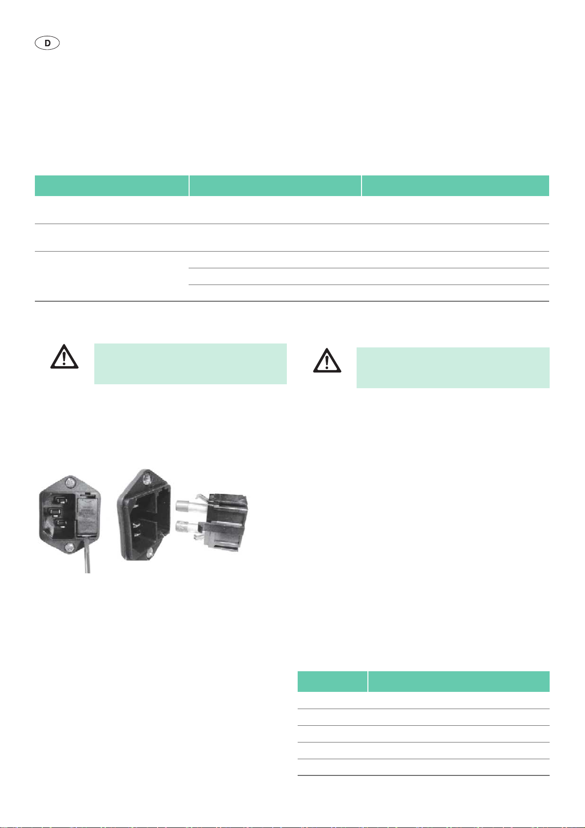
Aesculap®
Full HD 3CCD Kamerasystem PV440
Störung Ursache Behebung
Bild zu hell bzw. überblendet Belichtungsmessung nicht optimal gewählt Taste 10 für die Modus-Einstellung drücken und die
optimale Belichtungsmessung wählen
Farbbalken-Diagramm am Monitor Kamerakabel nicht an Kamerakontrolleinheit
angeschlossen
Falsche Farbwiedergabe am Monitor Automatischer Weißabgleich fehlgeschlagen Automatischen Weißabgleich starten
Farbeinstellung am Monitor verstellt Auf Werkseinstellung zurücksetzen
Videokabel defekt Videokabel ersetzen
Kamerakabel an Kamerakontrolleinheit anschließen
8.1 Sicherungswechsel
Lebensgefahr durch elektrischen Stromschlag!
► Vor dem Wechsel der Sicherungseinsätze Netz-
GEFAHR
Vorgeschriebener Sicherungssatz: T 0,5 A L/250 V~; Art.-Nr. TA020394
► Rastnase am Sicherungshalter mit einem kleinen Schraubendreher
entriegeln.
► Sicherungshalter herausziehen.
► Beide Sicherungseinsätze wechseln.
► Sicherungshalter wieder so einsetzen, dass er hörbar einrastet.
Abb. 3 Sicherungswechsel
Hinweis
Wenn die Sicherungen häufig durchbrennen, ist das Gerät defekt und muss
repariert werden, siehe Technischer Service.
stecker ziehen!
9. Technischer Service
Verletzungsgefahr und/oder Fehlfunktion!
► Produkt nicht modifizieren.
WARNUNG
► Für Service und Instandsetzung wenden Sie sich an Ihre nationale
B. Braun/Aesculap-Vertretung.
Modifikationen an medizintechnischer Ausrüstung können zu einem Verlust der Garantie-/Gewährleistungsansprüche sowie eventueller Zulassungen führen.
Service-Adressen
Reparaturabwicklung Kamerasysteme:
Aesculap FLEXIMED GmbH
Reparaturservice
Robert-Bosch-Str. 1
79211 Denzlingen / Germany
Phone: +49 7666 93 21 0
Fax: +49 7666 93 21 580
E-mail: techserv@aesculap-fleximed.de
Telefon-Hotline bei Problemen mit elektrischen Geräten und Gerätekom-
binationen:
Phone: +49 7461 95 1601
Weitere Service-Adressen erfahren Sie über die oben genannte Adresse.
28
10. Zubehör/Ersatzteile
Art.-Nr. Bezeichnung
PV442 Kamerakopf und Kamerakabel
PV441 Kamerakabel
PV126S Endo-Objektiv mit Zoom
PV127S Festbrennweiten-Endo-Objektiv
TA020394 Sicherungssatz T 0,5 A L/250 V~
 Loading...