

Aesculap Craniotome GB265 Service manual
Aesculap Power Systems
Service Manual
Craniotome GB265R, GB268R and Macro Craniotome GB299
Service-Manual
Craniotom GB265R, GB268R und Makro-Craniotom GB299
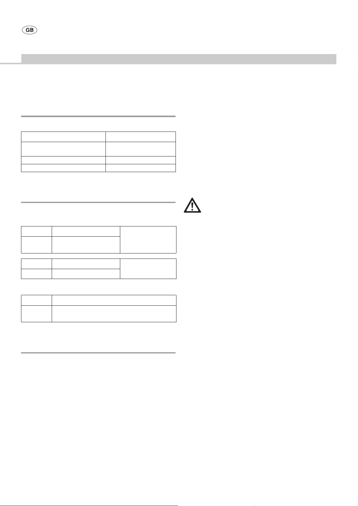
GB299801
GB299204
TA003323 (1x)
GB266203
TA005803
TA003904
GB299209
TA005799
GC303R
GB299207
TA005581
GB299208
TA005761
GB299205
TA003323
GB299805
GB299203
TA005761
GB299202
GB131202
GB125312
TA 005 801
TA003323 (3x)
TA005800
TA003189
TA004018
GB115801

Aesculap Power Systems
Craniotome GB265R, GB268R and Macro Craniotome GB299
Copyright inform ation
Copyright© 2006
Aesculap AG & Co. KG®
All rights reserved 08/ 06
This service information is copyrighted. This service information must not
be copied or reproduced by other means either in whole or in part without
the express permission of Aesculap AG & Co. KG.
This manual is intended for informational purposes only. Ownership of this
manual alone does not constitute or imply authorization to service the
product.
The technical information, illustrations and dimensions contained in this
manual are non-binding. No claims may be made on the basis of the
information contained here in. We reserve the ri ght to make improvements
without altering this documentation. We reserve the right to make
technical changes without prior notice.
Main address for servicing:
Aesculap Technischer Service (ATS)
Am Aesculap-Platz
78532 Tuttlingen / Germany
Phone: +49 7461 95-2700
Fax: +49 7461 16-2887
E-mail: ats@aesculap.de
Other service addresses can be obtained through the address i ndicated
above.
Manufacturer’s liability
We expressly point out that we can accept responsibility for any effects
on the safety, reliability, and performance of our medical products, if and
only if:
• any assembly, extensions, readjustments, modifications, or repairs are
performed by technically experienced, knowledgeable and trained
personnel and
• the medical products are used as set forth in the instructions for use.
It is possible to learn to service the products through an appropriate
course of instruction given on the premises of Aesculap about the r elevant
medical products. To arrange for such a course, contact Aesculap
Technical Service (ATS).
To ensure that your Aesculap warranty remains valid, we recommend that
only spare parts that have been factory tested by Aesculap be used for
repairs. Spare parts, as well as the relevant tools, can be ordered from
Aesculap Technical Service (ATS). Any unauthorized opening and/or
alterations of the medical product by third parties lead to the exclusion of
our liability, as far as a fault is attributable to such unauthorized opening
and/or alteration of the product. Aesculap cannot accept responsibility for
the use of unsuitable spare parts, tools or devices. After repairs, dropping,
severe damage or misuse, the product should be inspected by a qualified
person.
This manual refers to the product as it was when the manual was
prepared. Technical changes may be made at any time, particularly in
software.
General advisory
This service manual contains illustrations and explanations. Each
explanation covers the following: modes of operation, spare parts list,
assembly, disassembly, functionality test, and the section tools/devices (if
applicable).
For further information about a specific product (e.g. troubleshooting list,
accessories) consult the relevant user instructions.
Literature Art. no.
Instructions for use TA005834
It is crucial that extreme cleanliness be maintained when the products
described below are repaired. All products must undergo a functionality
test after being repaired. If, in the course of a repair, a labeled component
is replaced, the labeling must be transferred to the spare part. Either the
original label should be used or the spare part bearing the relevant label
should be ordered. To this end, be sure to include the applicable
information when ordering.
Unless otherwise indicated, all medical products should be inspected
annually.
General information about motors and handpieces
It is critically important that ball bearings be inspected annually. Even the
slightest defect or soiling can lead to overheating during use, which would
render the product unusable. If for the repair of, e.g., a motor a ball
bearing has to be replaced, it is best in most cases to replace all other ball
bearings as well.
If it is necessa ry to heat up adhes ive joints during disassembly, a hot-air
blower is the appropriate tool. The smallest possible nozzle should be used
so as to avoid damaging other components. When gluing parts together,
make certain that the surfaces to be joined are absolutely clean and fr ee
of grease. We recommend using Loctite Rapid Cleaner 7063 for this
purpose (WS. no. 520001750). Only u se adhesives listed in this manual.
Follow the glue manufacturer’s recommendations.
Lubricate components with the recommended Aesculap product only.
Following disassembly, clean all components thoroughly and inspect them
to ensure that they are undamaged. Do not install any component of
whose status you are uncertain. Products must always be test-run for
several minutes after being repaired.
2
Contents
1. Safe handling...................................................................................................3
2. Tools, auxiliary materials, supplies............................................................3
2.1 Tools.................................................................................................................... 3
2.2 Auxiliary materials..........................................................................................3
2.3 Supplies............................................................................................................. 3
3. Expendable parts/Replacement parts........................................................4
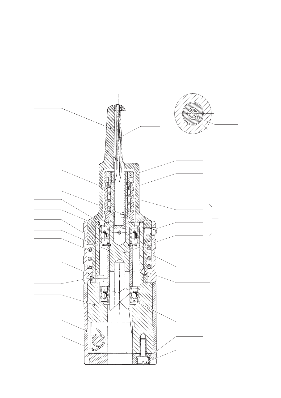
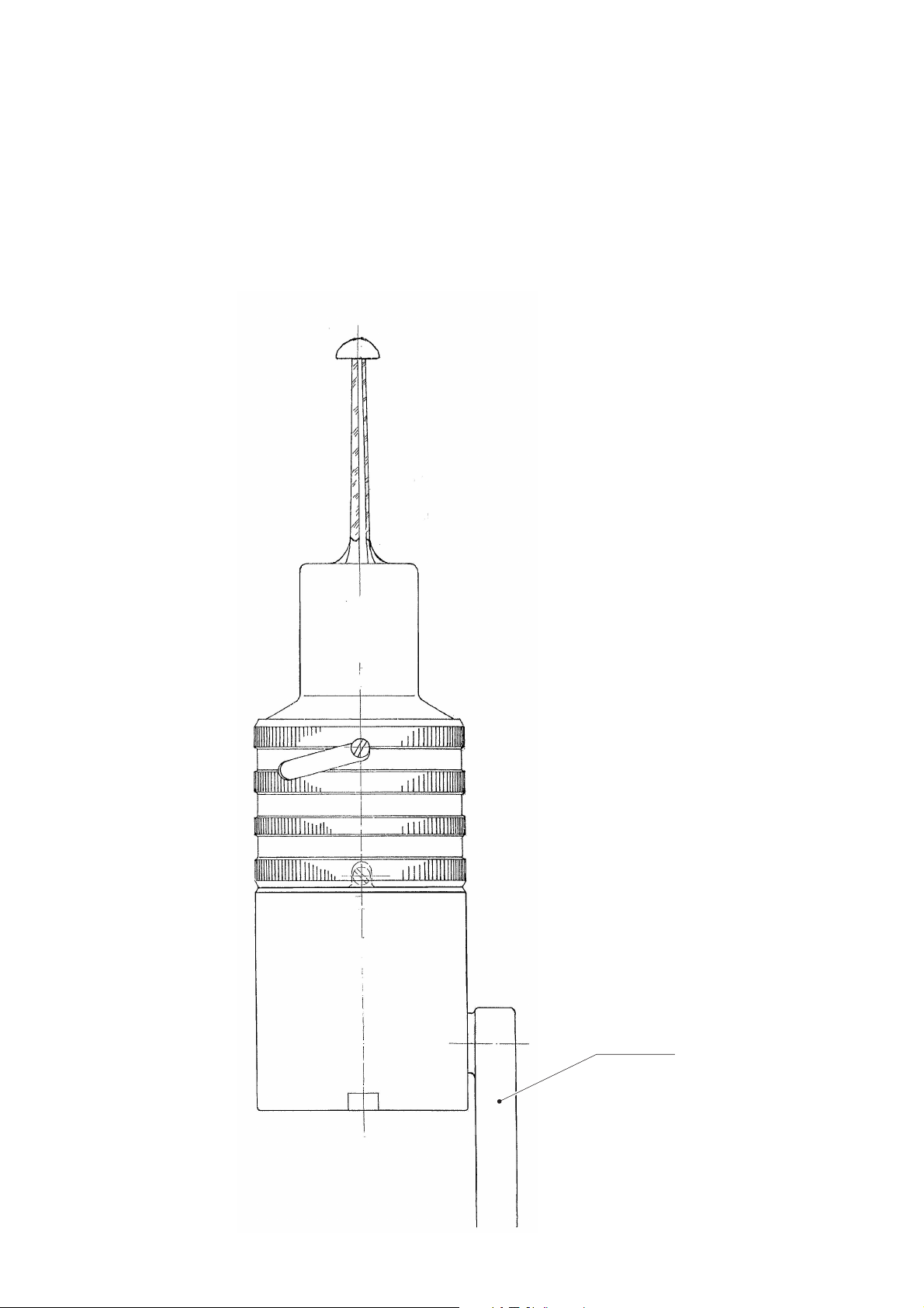
4. Designation of the craniotome elements ...............................................4
5. Basic preparations and maintenance........................................................4
5.1 Preparations.....................................................................................................4
Surface inspection......................................................................................... 4
Checking the connections between elements....................................... 4
Function tests..................................................................................................4
5.2 Maintenance....................................................................................................4
6. Troubleshooting list........................................................................................5
7. Disassembling..................................................................................................6
7.1 Disassembling the support foot ................................................................. 6
Disassembling support foot GB266.......................................................... 6
Disassembling support foot GB298.......................................................... 6
7.2 Disassembling the housing (GB267) ........................................................6
7.3 Disassembling the spindle (GB267) .......................................................... 6
7.4 Disassembling the housing (GB299) ........................................................6
7.5 Disassembling the spindle (GB299) .......................................................... 6
8. Assembling......................................................................................................10
8.1 Preliminary work.............................................................................................7
8.2 Pre-assembling the spindle (GB267) ... ...................... .... ..................... .... .. 7
8.3 Assembling the housing (GB267) ..............................................................7
8.4 Pre-assembling the spindle (GB299) ... ...................... .... ..................... .... .. 7
8.5 Assembling the housing (GB299) ..............................................................7
8.6 Assembling the support foot....................................................................... 7
Assembling support foot GB266................................................................ 7
Assembling support foot GB298................................................................ 7
8. Postmaintenance ..........................................................................................11
9.1 Function tests..................................................................................................8
10. Parts list.......... ... ...................... .... ..................... .... ..................... .... .................... 8
10.1 GB265R .......... ........................................... ........................................... .............8
10.2 GB268R .......... ........................................... ........................................... .............9
10.3 GB299 ............ ....................................... .................................... ........................ 9
1. Safe handling
! Operate craniotome GB265R, GB268R and GB299 with authentic
Aesculap accessories only.
! To avoid damage to the product, do not knock craniotome GB265R,
GB268R and GB299 against hard objects.
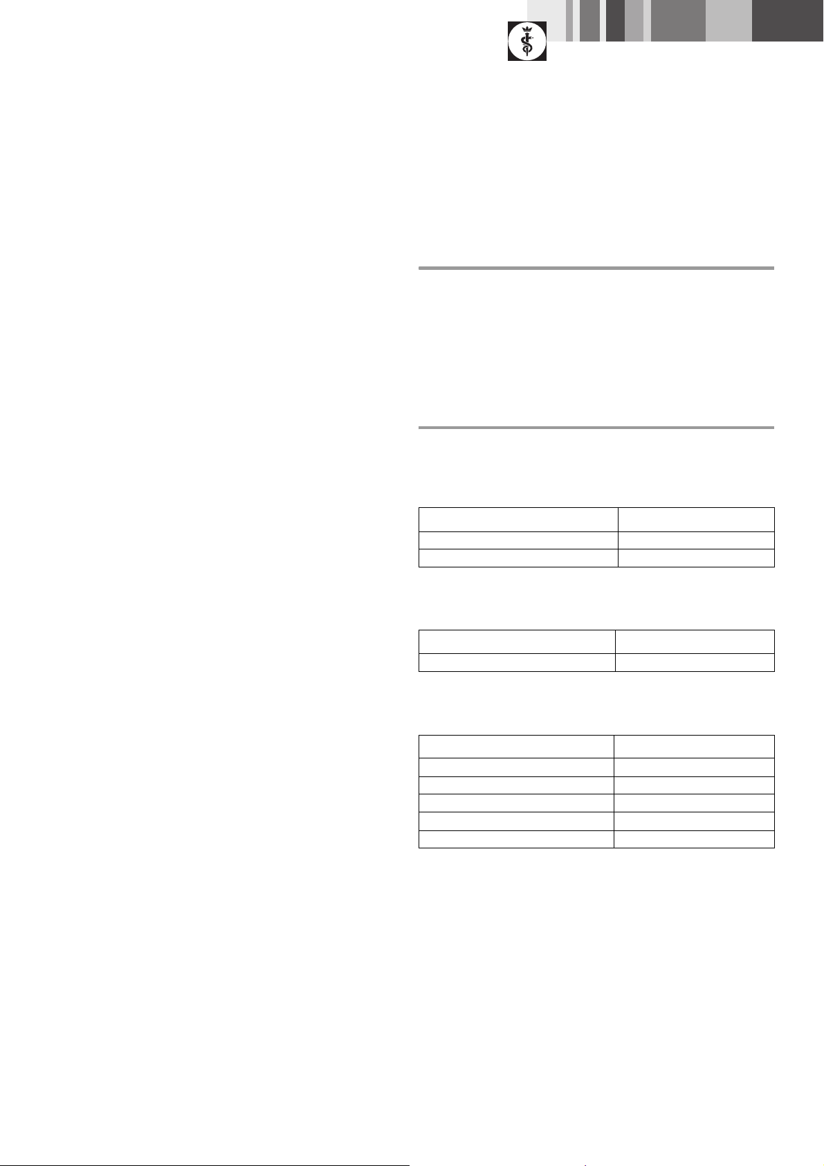
2. Tools, auxiliary materials, supplies
2.1 Tools
Designation Art. no.
Slotted screwdriver without
Clamping jaws without
2.2 Auxiliary materials
Designation Art. no.
Instructions for use TA005834
2.3 Supplies
Designation WS. no.
Special grease MI-setral-FKR 2 537001602
Loctite 222 560001813
Loctite 640 560001820
Eloxal Cleaner JG601
Oil spray GB149
3
Aesculap Power Systems
Craniotome GB265R, GB268R and Macro Craniotome GB299
3. Expendable parts/Replacement parts
Designation Art. no.
Radial ball bearing 8 x 16 x 6 ALSI
(x2)
Grooved pin D IN 1473 1.2 x 5 NR TA005387
Locking washer TA003904
TA005800
4. Designation of the craniotome elements
Micro craniotomes
GB267 Handpiece only
GB266/
GB266M
GB267 Handpiece only
GB298 Support foot (fixed)
Macro craniotome
GB299 Handpiece (Macro) only, with fixed support foot GB298R
GB295 Pendular support foot craniotome compl. (screwed
Pendular support foot
together), with pendular support foot GB266
Combined GB265R
Combined GB268R
Surface inspection
! Check surf ace s fo r:
–dents
–stains
– sharp edges
–glue residues
Checking the connections between elements
! Connect flexible shaft GA176.
! Turn flexible shaft GA176 by hand. Check that the gear turns smoothly
and without resistance.
Risk of injury while handling the cutter (sharp
cutting edges)!
WARNING
! Connect cutter GC303R.
! Check the locking and unlocking mechanism of cutter GC303R.
! Turn cutter GC303R by hand. Check that the cutter turns smoothly and
without resistance.
! Be careful w h en handling the cutter.
Function tests
! Check that the support foot turns freely and without slack under spring
pressure.
! Check craniotome GB265R, GB268R and GB299 for heat-up.
After 3 minutes of running, the temperature must not exceed 41 °C.
! Check craniotome GB265R, GB268R and GB299 for atypi cal running
noise, which would indicate defective bearings or couplings.
! Check all glued joints for firm seating.
! Spray through craniotome GB265R, GB268R and GB299 with oil spray
GB149.
5. Basic preparations and maintenance
5.1 Preparations
! Rethread every thread, using a tapper.
! Clean all components, remove all silicone and Loctite residues, and
degrease.
! Clean the surfaces of craniotome GB265R, GB268R and GB299 with
Eloxal Cleaner JG601.
! Lubricate open radial ball bearing TA005800 with special grease MI-
setral-FKR 2, WS.-no. 537001602.
4
5.2 Maintenance
In order to ensure reliable operation, Aesculap recommends maintenance
after every 300 reprocessing cycles or at least once a year.
 Loading...