

Page 1
Solar Link 1000
OPERATING INSTRUCTIONS
Patent Pending
Page 2
Sierra Wave® Solar Link 1000 #9675
The Sierra Wave Solar Link 1000 is a heavy duty and efficient portable power center offering 1000 watt
hours of rechargeable power bringing portable energy to your home, office, or job site. Whether it is used
as a backup power supply for areas experiencing power outages due to natural disaster or as a mobile
generator for a campsite, the Solar Link 1000 powers your world. Charge it from available electricity or
operate self-sufficiently using one of the Sierra Wave Solar Collectors. No set-up is required, just plug in
and go. Includes a 120V AC wall charger.
The Solar Link 1000 uses LiFePo4 (lithium iron phosphate) battery technology. This battery type offers
a long life cycle and reliable performance. Couple that with a linear power management system to make
the Solar Link 1000 the most advanced portable power system on the market.
IMPORTANT wARNINGS & SAFEGUARDS
Read all instructions thoroughly before operating this unit to avoid injury to self or property and avoid
damage to the unit. Keep instructions handy for reference during use.
ENERGIZED EQUIPMENT - ELECTRICAL SHOCK & EXPLOSION HAZARDS
GENERATES LETHAL VOLTAGES
• Do Not submerge in liquid or operate in wet environments. Device is not waterproof or
water resistant. Operate in dry environments only.
• Do Not operate in flammable or explosive environments
• Do Not operate if the unit is damaged in any way including loose electronics or if
charging cords are frayed and wires are exposed.
• Do Not plug Inverter 120V AC outlets into external 120V AC outlets of any kind
• Do Not place foreign objects inside the power outlets
DANGER
• Do Not disassemble. There are no user serviceable parts. Contact the manufacturer for
all repairs.
• Do Not use any AC powered devices over 1000W for risk of damage to the batteries or
inverter
• Do Not use to operate any medical life support equipment
• Consult your physician before using with CPAP devices or other non-life support
medical equipment
• Do Not block the air inlets or vents
• Do not replace fuses with larger amperage values
CAUTION
• Not recommended for use or storage below 14º (-10ºC) or above 120ºF (49ºC). Place
out of direct sunlight to prevent overheating.
• Administer close supervision when operating around children or persons with
disabilities
• Check dangerous goods shipping regulations before shipping via air
SOlAR lINk 1000 IS ONly SERvICEAblE by AN AUThORIzED REPAIR FACIlITy. DO
NOT DISMANTlE. wARRANTy IS vOID IF ThE DEvICE IS OPENED by UNAUThORIzED
PERSONNEl. CAll AERvOE INDUSTRIES, INC. AT 800-227-0196 FOR REPAIR
INFORMATION.
2
Page 3

The limited warranty described in the warranty is the sole and exclusive warranty provided by Aervoe
Industries, Inc. In no event will Aervoe be liable for any indirect or incidental damages or losses of
any kind arising from or as a result of misuse or abuse, or the incorrect installation or operation of the
product.
FCC REQUIREMENTS
Warning: Changes or modifications to this unit not expressly approved by the party responsible
for compliance could void the user’s authority to operate the equipment.
Note: This equipment has been tested and found to comply with the limits for a Class B digital device,
pursuant to Part 15 of the FCC Rules. These limits are designed to provide reasonable protection
against harmful interference in a residential installation. This equipment generates, uses, and can
radiate radio frequency energy and, if not installed and used in accordance with the instructions, may
cause harmful interference to radio communications. However, there is no guarantee that interference
will not occur in a particular installation. If this equipment does cause harmful interference to radio
or television reception, which can be determined by turning the equipment off and on, the user is
encouraged to try to correct the interference by one or more of the following measures:
• Reorient or relocate the receiving antenna
• Increase the separation between the equipment and receiver
• Connect the equipment into an outlet on a circuit different from that to which the receiver is
connected
• Consult the dealer or an experienced radio/TV technician for help
Operation is subject to the following two conditions: (1) this device may not cause harmful
interference, and (2) this device must accept any interference received, including interference that may
cause undesired operation.
3
Page 4
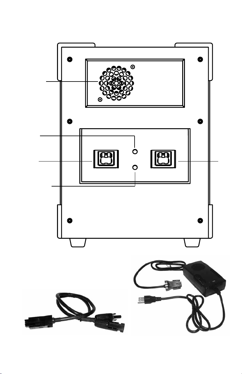
PARTS IDENTIFICATION
Inverter
Exhaust Fan
Solar
Input LED
Solar IN
Solar Charge
Complete LED
DC IN
POWER IN
120v AC
ChARGER
ANDERSON TO MC4
ADAPTER CAblE
4
Page 5

Earth
Ground
120V AC
Outlets
Inverter
ON/OFF
Status LEDs
Volt/AMP
Meter
Aux. USB
Port
DC ON/OFF
Battery
Meter
ON/OFF
Main Power
Keyhole
MAIN POwER kEy
12V DC
Outlets
12V DC
Fuses
USB PortsBattery Meter
POWER OUT
INvERTER REMOTE
CONTROl
5
Page 6

ChARGING
For maximum efficiency and battery life, charge before first use and after each use. Charge the
batteries every 4-6 months if it is being stored for a long period of time. Failure to properly charge as
listed below could damage the unit and affect performance.
Two methods of charging are available:
• Use the included 120V/220V – 15V 10A AC Charger
• Use a compatible solar panel (Sierra Wave #9580 & #9590 Solar Collectors recommended)
• Before charging or operating any devices, insert MAIN POWER KEY into the KEYHOLE and turn
clockwise to operate all charging and operation features. Turn counterclockwise to disengage all
operations. The key should be removed when not in use.
AC Charging: (included)
1. The INVERTER ON/OFF switch and the DC ON/OFF switch should be OFF.
2. Plug the 120V AC Charger into the DC IN socket. Make sure that the charger input voltage
selector is set for your area – this is either 120V or 220V. A 120V AC Charger is provided with
the unit. A 220V AC Charger may be purchased separately if required.
3. Find a suitable 120V AC outlet and plug in the power cord.
4. The RED LED on the charger will glow when charging is in progress.
5. The GREEN LED on the charger will glow when a complete battery charge is reached.
6. The BATTERY METER will indicate the strength of the battery – All 10 LEDs means the unit is
fully charged.
7. Disconnect the charger once charging is complete.
Solar Charging: (solar panel not included)
The Solar Link 1000 has a built in Linear Solar Charge Controller that can accept 12V and 24V solar
panel systems, up to a maximum input of 150 watts. Aervoe recommends the Sierra Wave #9580 80Watt Solar Collector or the Sierra Wave #9590 120-Watt Solar Collector.
The SOLAR IN socket is a four pin Anderson Power Pole™ connector. It has two RED (+) pins and two
BLACK (-) pins. An ANDERSON TO MC4 ADAPTER CABLE is provided to connect Sierra Wave solar
panels directly into the Solar Link 1000.
1. Connect a recommended or equivalently rated solar panel using the included ANDERSON TO
MC4 ADAPTER CABLE into the SOLAR IN socket. If using a solar panel or adapter cable other
than Sierra Wave, observe the proper +/- polarities and wattage recommendations.
2. Follow instructions provided with the solar panel.
3. When solar voltage is present, the SOLAR INPUT LED will glow RED.
4. When charging is complete the SOLAR CHARGE COMPLETE LED will glow GREEN.
5. The BATTERY METER will indicate the status of charging – All 10 LEDs means the unit is fully
charged.
6. Disconnect the solar collector once charging is complete.
Note: The BATTERY METER measures the battery voltage in a range of approximately 10.5 to 14.5 volts.
When a charging voltage is present the BATTERY METER will indicate the charging voltage level, not the
battery voltage. When voltage sources are removed, the Meter will again indicate the battery voltage level.
The BATTERY METER can be left on to monitor the battery voltage levels during charging or power center
operation. It should be switched OFF when not in use or during long term storage.
6
Page 7

OPERATING INSTRUCTIONS
Once charged, the Solar Link 1000 is ready to use. All power outputs may be used simultaneously as
long as the total peak wattage draw of all devices plugged in does not exceed 1000W. Check all device
specifications to make sure they are compatible with the Solar Link 1000. For long battery life and
maximum recharge cycles it is best to keep the total of all power output loads in the 500-600W range
or lower. Running at maximum output at all times may overheat the inverter and will severely reduce
the life of the battery. MAIN POWER KEY must be removed before storage or transportation.
120V AC and DC power options are available on the POWER OUT panel providing a wide range of AC
and DC product operation:
• 120V AC power
• DC power
120V AC Power Operation (Pure Sine Wave Inverter)
The 120V AC operation can safely power common AC appliances and devices rated at up to 1000W
Peak. The longest battery life and maximum recharge cycles will be attained using devices in the
500-600W range or lower. The INVERTER ON/OFF switch is located just above the BATTERY METER.
For convenience, an AUXILIARY USB PORT is also located on the front panel of the inverter so that any
USB device can be charged while the inverter is ON.
Note: When the battery voltage is reduced below 10.5V the inverter will sound an alarm and
the RED LED will glow. Switch the inverter OFF and recharge the batteries using the procedures
described in the Charging Section on page 6.
VOLT/AMP METER:
Continually displays the current battery voltage and the peak amperage draw. The operating range is
approximately 10.5V DC to 14.5V DC.
STATUS LEDs:
• The GREEN LED indicates that AC power is available at the outlets and the power inverter is
operating normally
• The RED (fault) LED indicates the inverter has shut down caused by low or high battery voltage,
overload, or excessive heat. The RED LED blinks for a few seconds during a normal power up
sequence. Turn the Inverter OFF, wait a few seconds, and turn it ON again to reset any faults.
GROUNDING:
An EARTH GROUND lug is provided if the power inverter will be used to power a permanent electrical
fixture. The ground wire should be connected to a building electrical ground point. If the power
inverter will be used as a temporary power source, the ground point may be connected to a “chassis
ground” point, for example a ham radio transceiver ground terminal.
Inverter Remote Control
A wireless remote control is provided with each Solar Link 1000 unit. The inverter must first be
powered ON in order to use the wireless remote to power the inverter ON or OFF from a distance (100
ft. max).
7
Page 8

DC Power
The DC power operation includes a DC ON/OFF switch that when switched ON provides power to the
USB ports and the 12V DC sockets. When the battery voltage is within it operating voltage range the
Green LED on the DC power switch will glow.
USB OPERATION:
1. Turn the DC power switch to the ON position
2. Plug in your USB device or USB charging cable
3. Up to 5V @ 2.0 A is provided to each USB dedicated charge port
4. Disconnect and turn the power off when not in use
12 VOLT DC OPERATION:
15A/150 watt each outlet.
1. Turn the DC power switch to the ON position
2. Plug in your 12V device’s power or charging cable into either of the 12V sockets
3. Disconnect and turn the power off when not in use
Note: When the battery voltage is reduced below 10.5V all DC outputs will automatically switch
OFF and the GREEN LED on the DC ON/OFF switch will no longer be ON. Recharge the batteries
using the procedures described on page 6.
8
Page 9

CARE AND MAINTENANCE
• Dust regularly with a clean dry cloth to prevent dust and dirt from building up on the vents and
power inputs/outputs
• Store in a clean, dry place when not in use
• Charge after each use, every 4-6 months, and before storing so it is ready to use when needed
• Turn the INVERTER ON/OFF, DC ON/OFF and BATTERY ON/OFF switches OFF and remove the
MAIN POWER KEY when not in use or before long term storage
TROUblEShOOTING
If your Solar Link fails to operate as specified, follow these troubleshooting steps to correct the issue.
If you still experience issues, please contact Aervoe Industries, Inc. at www.aervoe.com or 800-227-
0196.
Make sure the MAIN POWER KEY is inserted and ON.
Charging Issues
• Ensure all cords are connected securely
• Check power indicators on chargers and the Solar Link to make sure they are operating
• If using a solar collector to charge, ensure it is correctly positioned in direct sunlight
12V DC Output Failure
• Check the BATTERY METER to see if the Solar Link has sufficient battery charge available. If not,
follow the charging steps previously described on page 6.
• Ensure the DC ON/OFF switch is ON and the green light is ON
• Check to make sure that the 12V DC circuit protection fuse is not blown by removing the 15A
FUSE associated with the suspect 12V DC output plug. Inspect the fuse and replace if needed
with the same size and amperage rated fuse.
• Check the 12V DC outlet for obstructions or other visible damage
• Verify the device being charged is working and not damaged
120V AC Output Failure
• Check the BATTERY METER to see if the Solar Link has sufficient battery charge available. If not,
follow the charging steps previously described on page 6.
• Ensure the INVERTER ON/OFF switch is ON and the green LED is ON
• Check the 120V AC outlet for obstructions or other visible damage
• Verify that the device being powered is working and not damaged
USB Output Failure
• Check the BATTERY METER to see if the Solar Link has sufficient battery charge available. If not,
follow the charging steps previously described on page 6.
• Ensure the DC ON/OFF switch is ON and the green light is ON
• Check the USB port for obstructions or other visible damage
• Verify the device being charged is working and not damaged
9
Page 10

TEChNICAl INFORMATION
SPECIFICATIONS
BATTERY TYPE LiFePo4 (lithium iron phosphate) 80Ah - 12.8V
BATTERY LIFESPAN 2000+ cycles (cycle = charge and discharge) 80% Depth of discharge
PROTECTION CIRCUIT Built-in over voltage, self-discharge, reverse polarity, and short circuit
SOLAR CHARGE CONTROLLER Built in 12V/24V 150W Linear Solar Charge Controller with over
INVERTER SPECIFICATIONS
• Output Wave Form
• AC Output Power (continuous)
• AC output (peak)
• AC Output Voltage
• AC Output Frequency
INVERTER SAFETY FEATURES • Electronic overload protection with automatic shutdown
FUSES (replaceable) 15A fuse (12V DC outlet)
DC INPUT POWER 15V 10A max
120V AC WALL CHARGER (INCLUDED) Input: 120V AC, 100-240V, 50/60hz, 100VA
RATED OUTPUT POWER 120V AC, 60hz, 1000w watts max PURE sine wave inverter, 740
OPERATING TEMPERATURE 32ºF TO 113ºF (0ºC TO 45ºC)
DIMENSIONS 15” x 14” x 9” (381 x 355 x 228mm)
WEIGHT 53 lbs. (24Kg)
CERTIFICATIONS Pending FCC Part 15
protection
voltage, over current and reverse polarity protection
• Pure Sine Wave
• 1000 Watts
• 2000 Watts
• 120V AC
• 60 Hz
• Built-in internal backup DC fused provides added safety
• Low battery voltage warning followed by automatic shutdown
• Over temperature protection with automatic shutdown
• Output short circuit protection
Output: 14.6V-15V DC, 10A
C-UL, FCC approved
watt-hours
12V DC - 15A, 820 watt-hours
USB (5V-2A) - 3 ports, 820 watt-hours
Pending UL 1741
10
Page 11

ChARGE TIME
Using #9580 80-Watt Solar Collector 10-12 hours
Using #9590 120W Solar Collector 6-8 hours
Using 120V AC Wall Charger 5-6 hours
SAMPlE RUN TIMES
#6905 Max Burton® Digital Stove To Go® 5-6 hours
#9710 Sierra Wave Work Light up to 75 hours
9730 Sierra Wave Portable Area Light 1 Light >200 hours, 3 Lights > 75 hours
30” Television 12-15 hours
Small thermo refrigerator 8-10 hours
Large refrigerator 2-4 hours from room temperature
Small microwave (<1000 watts) up to 30 minutes
Small power tools (drills, jig saw, sander) 2-10 hours
Laptop (65-90 watts) 6-8 hours
Smartphone Recharge > 70 times
Tablet computer Recharge > 35 times
To estimate how many hours of power are in the Solar Link, find the watt hour draw of the device that you wish
to power and divide into 740W (120V AC) or 820W (USB & 12V DC). (EX: One 12V 10-watt light = 82 hours of
continuous light). Lower run times may result when using devices above 600 watts.
1-year performance warranty on all products from date of purchase. Report to home office or local
Aervoe representative for examination. Because Seller cannot control Buyer’s handling or use of
product, Seller makes no warranty expressed or implied when not used or stored in accordance with
directions. This warranty is limited to repair or replacement of product within 30 days of receipt at the
Aervoe office in Gardnerville, NV and on original purchase only.
Times vary depending on user settings.
14-16 hours at set temperature
AvAIlAblE ACCESSORIES
Available at your local retailer or www.aervoe.com
#9580 Sierra Wave 80-Watt Solar Collector
#9590 Sierra Wave120-Watt Solar Collector
11
Page 12

12
9675inst; cs7/13
AERVOE INDUSTRIES, INC.
Gardnerville, NV 89410 • 1-800-227-0196
www.aervoe.com • mailbox@aervoe.com
 Loading...