

Page 1
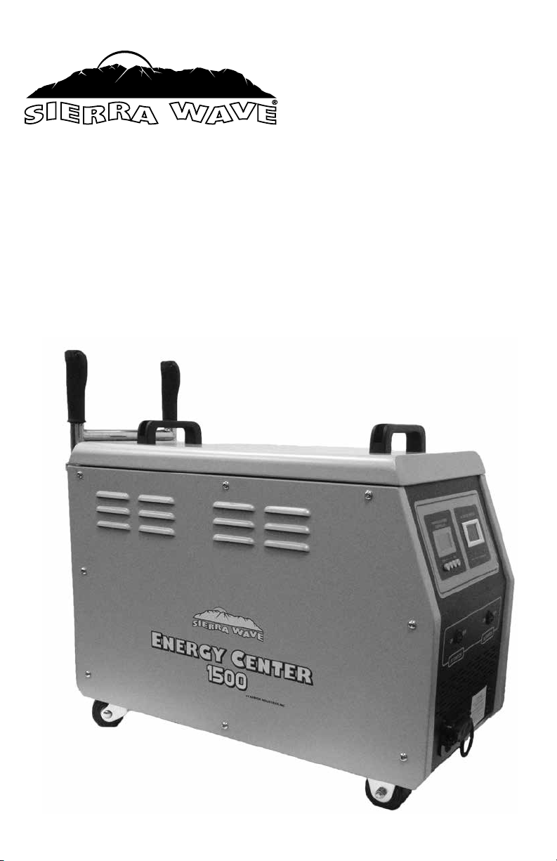
Energy Center 1500
OPERATING INSTRUCTIONS
Page 2
Sierra Wave® Energy Center 1500 #9680
The Sierra Wave Energy Center 1500 is a contractor-grade, rechargeable power center bringing
portable energy to your home, office, or job site. Whether it is used as a backup power supply for areas
experiencing power outages due to natural disaster or as a mobile generator for a job site, the Energy
Center 1500 powers your world. Unlike gas generators, this unit is silent and does not emit hazardous
fumes. Charge it from available electricity or operate self-sufficiently using a Sierra Wave Solar Collector
or compatible wind turbine. Just plug in and go.
The Energy Center 1500 uses a 120Ah deep cycle, AGM, non-spillable battery that can be expanded to
240Ah using a Energy Center Buddy #9681 (sold separately) and comes with a built-in wind and solar
charge controller.
Inverter Information: The inverter is a high-quality and powerful 1500 watt pure sine wave inverter
that is required when powering certain electronics, such as, industrial tools, refrigerators, freezers,
communication equipment, digital TVs, etc. Using a competitive unit with a modified sine wave inverter
for these items will not work or would cause damage.
IMPORTANT WARNINGS & SAFEGUARDS
Read all instructions thoroughly before operating this unit to avoid injury to self or property and avoid
damage to the unit. Keep instructions handy for reference during use.
ENERGIZED EQUIPMENT - ELECTRICAL SHOCK & EXPLOSION HAZARD
GENERATES LETHAL VOLTAGE
DANGER
• Do Not submerge in liquid or operate in wet environments. Device is not waterproof or
water resistant. Operate in dry environments only.
• Do Not operate in flammable or explosive environments
• Do Not operate if the unit is damaged in any way including loose electronics or if
charging cords are frayed and wires are exposed
• Never cross connect POS (+) and NEG (-) terminals or battery cables
• Do Not plug inverter 120V AC outlets into external 120V AC outlets of any kind
• Do Not place foreign objects inside the power outlets
• Do not replace fuses with larger amperage values
• Do Not block the air inlets or vents
• Not recommended for use or storage below 10º (-12ºC) or above 120ºF (49ºC). Place
out of direct sunlight to prevent overheating.
• Not intended for use as an Uninterruptable Power Supply (UPS)
• Administer close supervision when operating around children or persons with
disabilities
Do Not use to operate any medical life support equipment
Consult your physician before using with CPAP devices or other
non-life support medical equipment
2
Page 3

GROUNDING
A chassis ground lug is located on the bottom of the back panel. This allows an earth ground wire
bond from the Energy Center 1500 chassis, when applicable. Examples of required applications would
be when powering permanent or long-term 120V AC electrical devices and equipment, some ham
radios, and other communication equipment. Follow your equipment’s user manual guidelines or
contact the manufacturer for assistance. More information on grounding can be found in the National
Electrical Code and local electrical codes.
THE ENERGY CENTER 1500 BATTERY AND FUSE REPLACEMENT ARE THE ONLY
FEATURES SERVICEABLE BY THE USER. ALL OTHER REPAIRS MUST BE PERFORMED
BY AERVOE INDUSTRIES, INC. OR AN AUTHORIZED REPAIR FACILITY. FAILURE TO
FOLLOW THESE GUIDELINES CAN DAMAGE THE UNIT, CAUSE INJURY, AND VOIDS
THE PRODUCT WARRANTY. CALL AERVOE FOR ADDITIONAL INSTRUCTIONS OR
TROUBLESHOOTING INFORMATION.
The limited warranty described is the sole and exclusive warranty provided by Aervoe Industries, Inc. In
no event will Aervoe be liable for any indirect or incidental damages or losses of any kind arising from or
as a result of misuse or abuse, or the incorrect installation or operation of the product.
FCC REQUIREMENTS
Warning: Changes or modifications to this unit not expressly approved by the party responsible
for compliance could void the user’s authority to operate the equipment.
Note: This equipment has been tested and found to comply with the limits for a Class B digital device,
pursuant to Part 15 of the FCC Rules. These limits are designed to provide reasonable protection
against harmful interference in a residential installation. This equipment generates, uses, and can
radiate radio frequency energy and, if not installed and used in accordance with the instructions, may
cause harmful interference to radio communications. However, there is no guarantee that interference
will not occur in a particular installation. If this equipment does cause harmful interference to radio
or television reception, which can be determined by turning the equipment off and on, the user is
encouraged to try to correct the interference by one or more of the following measures:
• Reorient or relocate the receiving antenna
• Increase the separation between the equipment and receiver
• Connect the equipment into an outlet on a circuit different from that to which the receiver is
connected
• Consult the dealer or an experienced radio/TV technician for help
Operation is subject to the following two conditions: (1) this device may not cause harmful
interference, and (2) this device must accept any interference received, including interference that may
cause undesired operation.
3
Page 4
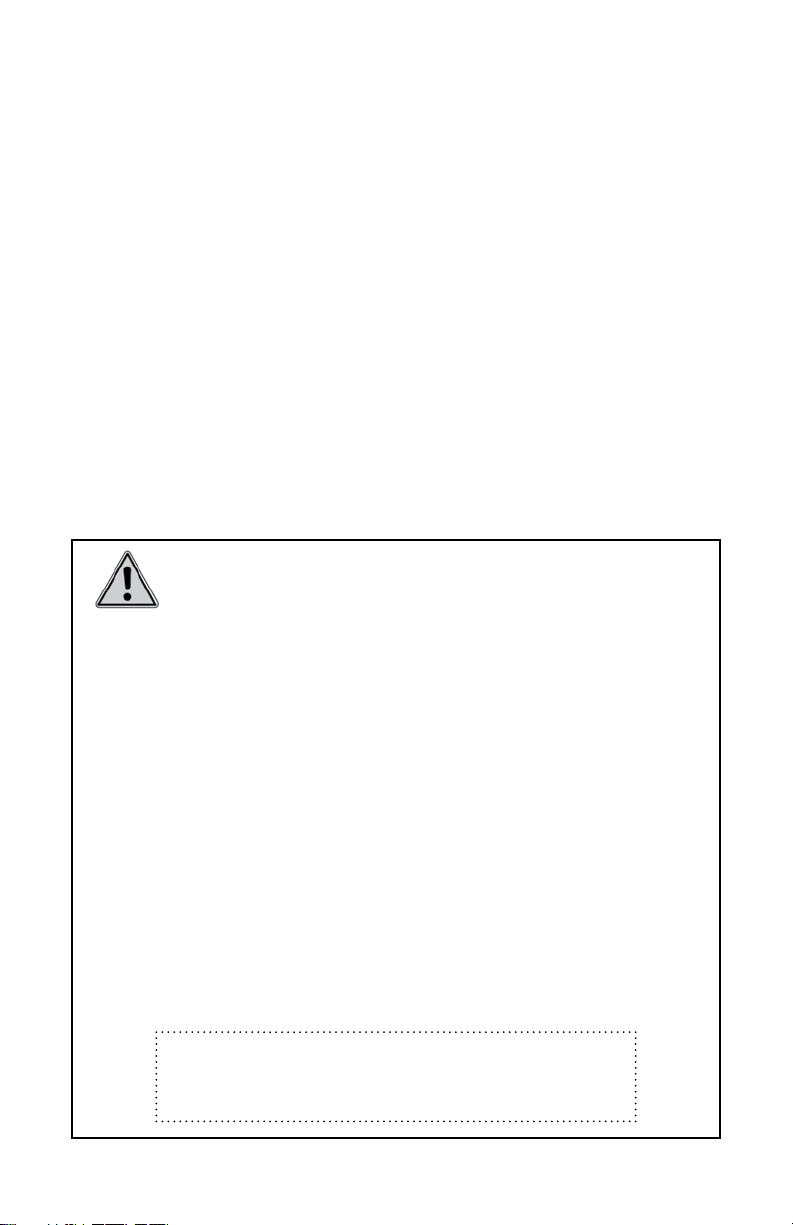
PARTS IDENTIFICATION
Handle
WIND&SOLAR HYBRID
CONTROLLER
Enter Esc
(-)(+)
ON OFF ON OFF
DC SWITCH
AC STATUS MONITOR
warning
working
fully charged
AC SWITCH
charging
Telescoping Handles
Interconnecting
Terminal
Caster Wheels
FRONT
4
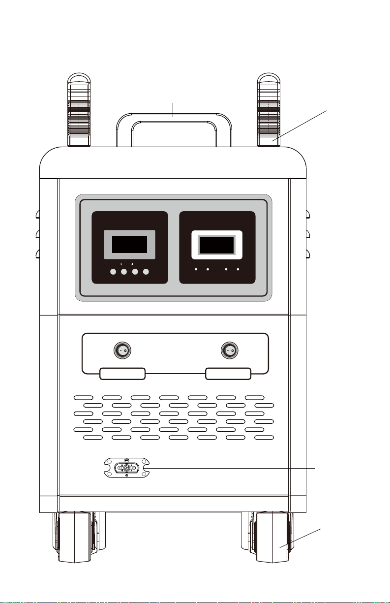
Page 5
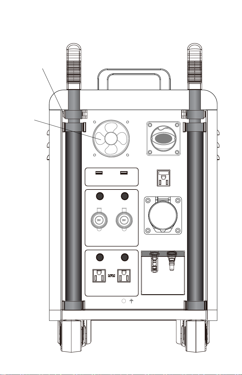
Telescoping
Handle
Clamps
Cooling Fan
5V/2A USB 5V/2A USB
FUS FUS
15A FUSE 15A FUSE
MAIN POWER
SWITCH
FUS
CHARGING
INPUT
DC 12V OUTPUT
15A MAX
15A FUSE 15A FUSE
AC 120V OUTPUT
15A MAX
DC 12V OUTPUT
FUS FUS
AC 120V OUTPUT
15A MAX
15A MAX
BACK
WIND TURBINE
INPUT
SOLAR
INPUT
5
Page 6

SET-UP
1. Remove the Energy Center from its packaging and place on a level surface. Make sure caster
wheels are moving freely and all packaging has been removed, especially around the COOLING
FAN and vents.
2. Insert the telescoping handles into the mounted tubes on the back of the unit and clamp them
securely at the desired height.
POWER CONTROL SWITCHES
• MAIN POWER SWITCH & KEY: the main power switch has two functions.
1. Activates the AC charger, battery, power inputs, and power outputs. Place in the ON
position during charging or when using power.
2. Security key. When in the OFF position, turn 45º to the left and remove the key. This will
make the Energy Center inoperable to anyone without the key. Should be removed when
stored for long periods.
• AC SWITCH: controls the ON/OFF operation of the inverter and 120V AC outputs
• DC SWITCH: controls the ON/OFF operation of the 12V DC and 5V USB power outputs
ON OFF ON OFF
DC SWITCH
MAIN POWER
SWITCH & KEY
WIND & SOLAR CHARGE CONTROLLER
WIND & SOLAR HYBRID
CONTROLLER
Enter Esc
AC SWITCH
(-)(+)
Fig. 1
6
Page 7

Symbols & Definitions
Wind Turbine
Day: Solar input & charge detected
Night: No solar input detected Load status
Battery Status - Full
When flashing the battery is overcharged and won’t
stop until the battery voltage recovers.
Battery Status - Empty
When flashing the battery is over-discharged and
won’t stop until the battery voltage recovers.
Light Control - not available on the
#9680 Energy Center 1500
Time Control - not available on the
#9680 Energy Center 1500
Indicates a browsing feature is set. Parameters (volt, watt, amp and load value).
Indicates the first load output or the second
load output. All loads should be in ON and
LOAD appear concurrently, and indicates the
1 2
output mode is constant on.
Normal load
Load without output
When flashing indicates over-load. Remove load and
press Esc key to recover output.
Activates the manual brake to the wind turbine and
stops rotation.
Programming Information
1. The default screen will display as in Figure 1.
2. The blue LCD backlight will come on and remain lit for 10 seconds unless a button is pushed.
3. Press the (+) and (-) to cycle through the parameters
• Wind Turbine Input Voltage = WIND 00.00 V
• PV (solar) Input Voltage = PV 00.00 V
• Wind Turbine Input Wattage = WIND 00.00 W
• PV (solar) Input Wattage = PV 00.00 W
• Wind Turbine Input Amps = WIND 00.00 A
• PV (solar) Input Amps = PV 00.00 A
• Load Output Current = LOAD 00.00 A and shows the current draw from your 12V or USB
device when connected to either of these DC outputs
• Light Control & Time Control (not available on the #9680 Energy Center 100 and should be
kept at 0.0V
4. Press the Enter button to save parameters and return back to the browsing window.
5. Press the Esc button to return to the browsing window without saving a parameter. In the
browsing window, the Esc button is used as a manual reset key for load short-circuit or overload.
7
Page 8

AC STATUS MONITOR
• LCD displays volt and amp status of the
AC STATUS MONITOR
inverter during use and when in standby.
• LEDs indicate when the battery is
charging, fully charged, if there is a
warning, or its working status (operating
a device).
warning
working
fully charged
Fig. 2
charging
BATTERY INFORMATION (INSTALLATION & SPECIAL PRECAUTIONS)
The AGM (absorbed glass mat) batteries are valve regulated, non-spillable, and deep cycle type. These
batteries offer long cycle life when charged and maintained according to these operating instructions.
ELECTRIC SHOCK - SHORT CIRCUIT & EXPLOSION HAZARD
GENERATES LETHAL VOLTAGE
• Only qualified persons with experience handling 12V batteries and power systems
should perform the removal and installation of this battery or fuse.
• Follow all instructions and be familiar with the important safeguards listed.
• Before removing the battery access panels, the user must make sure the MAIN
DANGER
POWER SWITCH is in the OFF position.
• Remove all external power charging sources (AC, solar, or wind)
• Remove any devices connected to power outputs (120V AC, 12V DC or USB).
ENERGY CENTER 1500 #9680 (primary battery included):
• 12V/120Ah AGM battery installed in the Energy Center 1500 to charge and operate as outlined
• Includes a 12V DC interconnecting power terminal output used to connect the Energy Center
1500 and Energy Center Buddy together
ENERGY CENTER BUDDY #9681 (secondary battery sold separately)
• An additional 12V/120Ah AGM battery that connects to the Energy Center 1500 to increase
working capacity to 240Ah
• Includes 1 set of 12V battery charging cables that provide connection between the Energy Center
1500 and Energy Center Buddy through the interconnecting terminals
8
Page 9

Connecting and Charging the Energy Center 1500 & Energy Center Buddy Together
1. Read the instructins provided with the #9681 Energy Center Buddy
2. Place the Buddy within 2 ft. of the Energy Center so that the 12V POWER CHARGING CABLES
reach the INTERCONNECTING TERMINALS of each unit.
3. Turn the MAIN POWER SWITCH to the OFF position on both units.
NOTE: Failure to do so could cause damage to the unit.
4. Remove the DUST CAPS from the INTERCONNECTING TERMINALS on both units.
5. Use the 12V POWER CHARGING CABLES provided with the Buddy to connect the two units
together. Securely insert each end of the CABLE into the TERMINALS of each unit (either end
will work in either unit).
6. First turn ON the MAIN POWER SWITCH on the Energy Center 1500 and then on the Energy
Center Buddy.
7. The Buddy is now connected to the Energy Center 1500 for charging and disbursement of power.
For additional information about either unit, please review the Product Data Sheet available online.
Battery Replacement
In the event that the battery of either the Energy Center 1500 or the Energy Center Buddy require
replacement, please follow these instructions. IMPORTANT: replace with a matching 12V/120Ah AGM
specified battery (available from Aervoe Industries, Inc.). Other batteries and capacities could produce
incorrect charging or poor performance.
1. Turn the MAIN POWER SWITCH to the OFF position.
2. Disconnect all external batteries, cables, and devices.
3. Remove the side panels of the unit by carefully removing the screws.
4. Locate the battery (+) and (-) terminals and carefully remove the protective caps on the battery
terminals.
5. Disconnect the Negative Terminal (-) cable from the battery and set aside. Should be placed to
prevent arcing other cables and components.
6. Disconnect the Positive Terminal (+) cable.
7. Loosen the bolts that attach the battery to the metal frame and carefully remove the battery from
the compartment. Do not disrupt any other electronics.
8. Replace with a new battery, reversing the previous steps. Before replacing the side panel double
check that all connections are secure.
9. Once the battery is installed, it will need to be fully charged using any of the methods described
in the following section.
10. Dispose of the used battery by contacting your local Hazard Waste Center.
Battery Fuse Replacement
If the Energy Center 1500 or Energy Center Buddy will not provide power to the Interconnecting
Terminal outputs, a short circuit or overload may have occurred and the internal 200A safety fuse may
need to be replaced. Contact Aervoe Industries, Inc. at 800-227-0196 for a replacement fuse and
installation instructions. Replace only with the same fuse specified in this manual.
9
Page 10

CHARGING
For maximum efficiency and battery life, fully charge before first use, after each use, and every 30 days
during storage to protect battery life and performance. Disconnect all power sources when not using
the Energy Center. The COOLING FAN will run intermittently to prevent overheating during charging.
IMPORTANT: Read all instructions thoroughly including any instructions provided with the solar panel
or wind turbine used.
Three methods of charging are available. Any combination of these methods may be used at the same time.
For optimum battery performance, do not use the power output during charging.
• 120V AC power (included)
• Solar power (Sierra Wave #9590 Solar Collector recommended)
• Wind power (any compatible vertical or horizontal axis turbine)
AC Charging: (included)
1. Turn the MAIN POWER SWITCH to ON. Charging the unit without it in the ON position will cause
inadequate charging.
2. Connect the included 120V AC POWER CORD to the CHARGING INPUT on the unit and the other
end into a 120V electrical wall outlet.
3. The LED charging indicators on the AC STATUS MONITOR (Fig. 2) will show the progress of
charging.
• CHARGING (red) = charge in process
• FULLY CHARGED (green) = charge complete
4. Disconnect the AC power cord once charging is complete.
Solar Charging: (solar panel not included)
The Energy Center 1500 can be connected to a 12V solar panel, or multiple panels, with a maximum
combined solar output of 240 watts. Aervoe recommends the Sierra Wave #9590 120-Watt Solar
Collector. Two of these collectors may be connected together to achieve 240 watts.
1. Follow instructions provided with the solar panel.
2. Position the solar panel in direct sun as described in the instructions provided.
3. Turn MAIN POWER SWITCH to the ON position. Charging the unit without it in the ON position
will cause inadequate charging.
4. Connect the solar panel’s MC4 SOLAR CABLES to the SOLAR INPUT (+) & (-) MC4 connectors
on the Energy Center.
5. Refer to Fig. 1 for solar input status and the Wind & Solar Controller instructions if needed.
6. Disconnect the solar panel once charging is complete or if not in use. It may be left connected if
the Energy Center is also connected to a power output.
Wind Charging: (wind turbine not included)
The Wind & Solar Controller allows various styles of wind turbines to charge the Energy Center 1500
- up to 400 watts. An AC 12-24V 3-phase Power Connector is required to connect the turbine to the
Energy Center. This device is included with the Energy Center, but the user is required to wire it to their
turbine according to the manufacturer’s instructions.
• Wind turbines have rotating parts that intermittently start and stop during
operation. Maintain at least a 4 ft clearance from the turbine when operating.
DANGER
10
• Disconnect turbine from the Energy Center or other battery before servicing.
• Never operate the turbine when not connected to a Load such as the Energy Center
1500 or other axillary battery as damage could occur to the turbine.
(Continued)
Page 11

1. Follow instructions provided with the wind turbine and set up as directed.
2. Turn the MAIN POWER SWITCH to the ON position. Charging the unit without it in the ON
position will cause inadequate charging.
3. Connect the user wired 3-phase AC POWER CONNECTOR & WIND TURBINE POWER CORD to
the WIND TURBINE INPUT on the Energy Center.
4. Follow the instructions for your turbine to start charging using wind power. Refer to Fig. 1 for
wind input status and the Wind & Solar Controller instructions.
5. Disconnect the turbine from the Energy Center once charging is complete or not in use.
POWER OUTPUT
Once charged, the Energy Center 1500 is ready to use. All power outputs may be used simultaneously
depending on the battery charge level and each does not exceed the maximum power limits listed in the
specifications section in this operating instruction manual. IMPORTANT: Check device specifications
first to make sure they are compatible with the 120V AC, 12V DC, of 5V USB voltage and amp (watt)
ratings of the Energy Center 1500. Failure to do so could damage your device.
120V AC Power Operation (Pure Sine Wave Inverter)
The pure sine wave inverter provides the same stable 120V AC power as found in any home/office
electrical outlet and can safely power common AC appliances and devices rated up to 1500W with
1350W continuous operation.
1. Make sure the Energy Center is at least 50% charged (12.5V). A fully charged unit will produce
optimum results (13.7 - 14V range).
2. Turn the MAIN POWER SWITCH to the ON position.
3. Turn the AC SWITCH to the ON position.
4. Connect your AC device to either of the 120V AC/15A outlets to operate.
5. During use the AC STATUS MONITOR will display volts and amps being used and the
WORKING LED will illuminate.
6. Monitor the Wind & Solar Controller (Fig. 1) during use. The available battery voltage will
appear in the display.
7. A 15A replaceable fuse is located above each 120V/15A outlet and protects against short circuit
and overload. Replace as needed with the same fuse specified in this manual.
Note: When the battery voltage is reduced below 10.7V the inverter will sound an alarm and
automatically shut-down. Disconnect all AC devices and recharge the batteries using the
procedures described in the Charging section.
DC Power (12V or USB devices)
Operate devices or appliances from either of the two marine grade 12V DC 150W/15A outlets and/or
the two 5V/2A USB outlets.
1. Make sure the Energy Center is at least 50% charged (12.5V). A fully charged unit will produce
optimum results (13.7-14V range).
2. Turn the MAIN POWER SWITCH to the ON position.
3. Turn the DC SWITCH to the ON position.
4. Connect your device to any of the 12V DC or 5V USB outlets.
5. Monitor the Wind & Solar Controller (Fig. 1) during use. Follow the Wind & Solar controller
instructions if needed.
6. A 15A replaceable fuse is located above the 12V DC outlet and protects against short circuit and
overload. Replace as needed with the same fuse specified in this manual.
Note: When the battery voltage is reduced below 10.7V an alarm will sound and all DC outputs
will automatically shut down. Disconnect all DC devices and recharge the battery using the
procedures described in the Charging section.
11
Page 12

CARE AND MAINTENANCE
• Dust regularly with a clean dry cloth to prevent dust and dirt from building up on the vents and
power inputs/outputs
• Store inside in a clean, dry place when not in use. Keep from exposing to extreme cold and hot
environments.
• Charge after each use and every 30 days when stored so it is ready to use when needed
• Turn all power switches OFF when not in use and remove the MAIN POWER SWITCH/KEY
TROUBLESHOOTING
If your Energy Center fails to operate as specified, follow these troubleshooting steps to correct the issue. If
you still experience issues, please contact a Product Specialist at Aervoe Industries, Inc. at 800-227-0196
or www.aervoe.com.
USER SERVICEABILITY IS LIMITED TO BATTERY AND FUSE REPLACEMENT.
Never attempt to service other electronics and components as serious injury or
CAUTION
Problem: AC charging not working
• Confirm the 120V AC POWER CORD is fitted securely in the input port of the Energy Center and
electrical wall outlet; and that the GFI or circuit breakers have not been tripped
• Make sure the MAIN POWER SWITCH is in the ON position prior to charging and that the
CHARGING LED is illuminated under the AC STATUS MONITOR
• Verify the 10A AC protection fuse is not broken or missing (located above the 120V charging
input). Replace with a new fuse if necessary as specified in this manual.
• If the problem has not cleared up, call Aervoe for further assistance.
death could result.
Problem: Solar or wind turbine charging not working
• Make sure the MAIN POWER SWITCH AND DC SWITCH ARE in the ON position prior to charging
and that the WIND & SOLAR CONTROLLER display is functioning.
• Confirm that the connection cords between the solar panel or turbine and the Energy Center are
installed correctly.
• If using a solar panel, position it in direct sunlight. The panel will need to be repositioned
throughout the day to keep it in direct sunlight. Refer to your solar panel instructions.
• If using a wind turbine, make sure it is placed in an area that receives adequate wind speed.
Refer to your turbine instructions for wind speed information.
• Check the BATTERY STATUS . If it is flashing then an overvoltage or other fault has occurred.
Reset the system by disconnecting all power inputs and turning the Energy Center off and on
again. Reconnect the solar or wind turbine. If the problem has not cleared up, call Aervoe for
further assistance.
12
Page 13

Problem: 120V AC output failure
• Check the BATTERY STATUS to see if the Energy Center has sufficient battery charge
available. The system may have automatically shut-down due to low battery level. Disconnect
the AC device and follow the charging steps previously described for charging the unit.
• Ensure the MAIN POWER SWITCH and the AC SWITCH are in the ON position and the AC
STATUS MONITOR displays shows the AC volts and Amps in the display. When under load the
AC output will display amperes (A) used.
• Check the 120V AC output protection fuses and replace if needed with the same fuse specified in
this manual (located above the 120V AC socket).
• If the problem has not cleared up, call Aervoe for further assistance.
Problem: 12V DC or USB output failure
• Check that the LIGHT OFF/ON OUTPUT and TIMER program is OFF and the DC OUTPUT LOAD #1
or #2 are in the ON position. Refer to the Wind & Solar Controller section.
• Check the BATTERY STATUS to see if the Energy Center has sufficient battery charge
available. The system may have automatically shut-down due to low battery level. Follow the
charging steps previously described for charging the unit.
• Ensure the MAIN POWER SWITCH and the DC SWITCH are in the ON position and the WIND &
SOLAR CONTROLLER display is functioning.
• If the LOAD WITHOUT OUTPUT symbol is flashing, there is a possible overload. Remove the
12V or USB device and reset power to the unit by turning the Energy Center off and on again.
• If the LOAD symbol is flashing, there is a possible short-circuit. Remove the 12V or USB
device and 4eset the system by turning the Energy Center off and on again..
• Check the 12V DC output protection fuses and replace if needed with the same fuse specified in
this manual (located above the 12V DC socket).
• If the problem has not cleared up, call Aervoe for further assistance.
SERVICE AND REPAIR
The Energy Center 1500 battery and fuse replacement are the only features serviceable by the user. All
other repairs must be performed by Aervoe Industries, Inc. or an authorized repair facility. Failure to
follow these guidelines can damage the unit, cause injury, and voids the product warranty. Call Aervoe
and ask to speak with a product specialist for additional instructions or troubleshooting information.
800-227-0196.
13
Page 14

TECHNICAL INFORMATION
SPECIFICATIONS
PRIMARY BATTERY 12V DC/120Ah AGM deep cycle sealed
PROTECTION FUSES Battery: MIDI® style bolt-down fuse 32V/200A
ENERGY CENTER BUDDY #6981
(secondary battery sold separately)
INVERTER SPECIFICATIONS
SOLAR/WIND CHARGE CONTROLLER Rated battery voltage: 12V DC
AC POWER INPUT
SOLAR/WIND POWER INPUT Solar: 30V DC/240 watt max (MC4 connectors)
POWER OUTPUTS • 120V AC electrical receptacle: 2-outlets; AC 120/15A each.
OPERATING TEMPERATURE 32ºF TO 104ºF (0ºC TO 40ºC)
STORAGE TEMPERATURE -4ºF TO 14ºF (-20ºC TO 35ºC)
DIMENSIONS 31” x 14” x 25.5” (78.74 x 35.56 x 64.77cm)
WEIGHT 170 lbs. (77Kg)
CERTIFICATIONS FCC Part 15 Reg #STE130823188
14
Dimensions: 16” x 6.85” x 9’17” (407 x 174 x 209mm)
Cycle Charge Life: 500 plus (based on 80% discharge and full
recharge cycles)
AC Input: 10A/250V glass fuse
AC Output: 15A/250V 1 x 1.25 glass ceramic tube
12V DC Output: 15A/125V 5mm x 20mm glass tube
12V120Ah AGM
Used in parallel with the Energy Center will increase working capacity
up to 240Ah.
MAIN SPECIFICATIONS
• Output wave form: Pure sine wave
• Efficiency rating: 90%
• Output voltage: 120V AC/60Hz (+/-) 5V
• No load current: 0.4A - 0.8A
• Continuous power output: 1350 watts
• Max. power output: 1500 watts
• Overload power setting: 1800 watts
• Peak surge power: 2500-3000 watts
PROTECTION CIRCUIT
• Overvoltage: 15V DC (+/-) 0.2V
• Low voltage cutoff: 10.5V DC
• Over temperature: 140ºF (65ºC)
• Built-in audible alarms and shutdown
• 20A protection fuse
Charge shutoff voltage: 14.5V DC
Battery overvoltage protection: 15V DC (+/-) 0.2V
Battery overdischarge protection: 10.8V DC
Solar input rating: 30V DC/240 watts max
Wind input rating: 12/24V AC 3-phase/400 watts (50A max)
Dump load control mode: PWM
Wind turbine break current: 34A
DC load #1 and #2 outputs: 12V DC/15A each
AC power cord: 125V AC/10A rated, 5ft. (1.5m)
AC input: 80-140V AC/3A
AC input fuse: 250V/10A replaceable
3-Stage Charge
• Charge: 14.5V/15A
• Float: 13.7V DC
• Recharge: 12.5V
Wind: 12/24V AC 3-phase/400 watt max (includes 3-phase power
connector for connection to turbine power cord)
(Includes replaceable 15A fuses)
• 12V DC vehicle receptacle: 2-outlets; 12V DC/15A each; 300
watt max combined usage. (Includes replaceable 15A fuses)
• USB port: 2-ports; 5V DC/2A each
CE (EN50178:1997) Reg #STS130823425
Page 15

CHARGE TIME
Times are estimates based on ideal power conditions. Actual times will
depend on the battery’s charge state and solar and wind conditions.
120Ah Primary Battery 240Ah Primary & Secondary Battery Used
120V AC Charging 8-10 hours 18-24 hours
Solar Charging:
1-#9590 120W Solar Collector
2-#9590 120W Solar
Collectors
Wind Turbine Charging
10-20 MPH wind speed
20-25 MPH wind speed
12-14 hours
6-8 hours
15-18 hours
8-12 hours
24-28 hours
12-16 hours
25-35 hours
14-22 hours
120V AC DEVICE:
SAMPLE RUN TIMES
18.8 cu. ft. Refrigerator (100-150W)
Based on an already chilled refrigerator.
DIY Paint Sprayer (100-150W) 8-10 hours 18-20 hours
Sump or Water Pump (150-200W) 6-8 hours 16-18 hours
Electric Power Tools 1-5 hours 2-10 hours
Portable Heater 1-3 hours 2-6 hours
Window Air Conditioner (750-1000W) 1-3 hours 2-6 hours
LED Industrial Lighting (50-100W) 10-12 hours 20-25 hours
Laptop (50-75W) 18-20 hours 36-42 hours
Large Flat Screen TV 5-10+ hours 10-20 hours
Microwave Oven (1000W) Up to 1 hour Up to 2½ hours
Times are based on a fully charged units. Actual times
vary depending on device type/size and the output/load
connected. All values are based on 80% depth of discharge
for batteries and normal AC inverter loss.
120Ah Primary Battery 240Ah Primary & Secondary
Battery Used
8-10 hours 18-20 hours
15
Page 16

12V & USB DEVICE:
SAMPLE RUN TIMES
Times are based on a fully charged Energy Center 1500. Actual
times vary depending on device type/size and the output/load
connected. All values are based on 80% depth of discharge for
batteries.
120Ah Primary Battery 240Ah Primary & Secondary
12V Thermoelectric Cooler (40-50W) 30 hours 62 hours
Max Burton Digital Stove To Go #6905
(100-130W)
Sierra Wave Portable/Rechargeable LED
Work Light #9710 (10W continuous)
Sierra Wave Portable Area Lights #9721
(9W)
Tablets such as iPad, Kindle, etc. (1012Wh)
11 hours 24 hours
120 hours 250 hours
130 hours 270 hours
Over 100 full recharges Over 200 full recharges
Battery Used
1-year performance warranty on all products from date of purchase. Report to home office or local
Aervoe representative for examination. Because Seller cannot control Buyer’s handling or use of
product, Seller makes no warranty expressed or implied when not used or stored in accordance with
directions. This warranty is limited to repair or replacement of product within 30 days of receipt at the
Aervoe office in Gardnerville, NV and on original purchase only. See inclosed warranty card for complete
information.
16
AVAILABLE ACCESSORIES
Available at your local retailer or www.aervoe.com
#9590 Sierra Wave 120-Watt Solar Collector
#9681 Energy Center Buddy
AERVOE INDUSTRIES, INC.
Gardnerville, NV 89410 • 1-800-227-0196
www.aervoe.com • mailbox@aervoe.com
9680inst; cs11/13
 Loading...