

Page 1
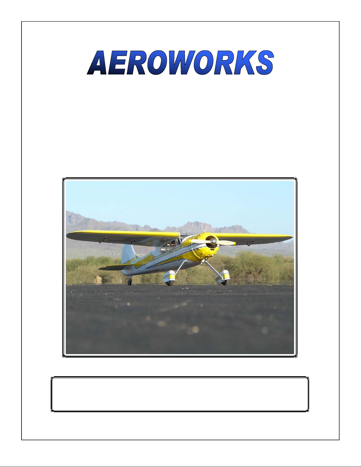
1.80 Cessna 195 ARF-QB
(Quick Build)
ASSEMBLY MANUAL
AEROWORKS
4903 Nome Street, Denver, CO. 80239 - Phone 303-371-4222 - Fax 303-371-4320
E-mail - [email protected]
1
Page 2

1
TABLE OF CONTENTS
Page
Aeroworks Contact Information ………………………………………………………………. 3
Introduction ……………………………………………………………………………………... 4
Kit Contents……………………………………………………………………………… ……… 5
Items Needed To Complete ……………………………………………………………………... 9
Removing Cockpit Hatch & Instrument Panel ……………………………………………….. 10
Tightening and Re-shrinking the Covering …………………………………………………… 11
Check Seams and Overlaps for Good Seal ……………………………………………………. 12
Ultracote™ Colors ……………………………………………………………………… …….. 13
Wing Assembly………………………………………………………………….……………….. 14
Stab and Elevator Assembly……………………………………………………………………. 21
Fin/Rudder and Pull-Pull Cable Assembly ………………………….………………………… 29
Pull-Pull Rudder Servo Installation…………………………………………………………….. 33
Tail Wheel Installation ………………………………………………………………………….. 39
Main Landing Gear, and Wheel Pants Assembly ……..…………………………….………… 41
Glow Engine Installation 4 Stroke …………....……………………………………………….. 44
Glow Engine Installation 2 Stroke …………....……………………………………………….. 49
Remote Glow Installation……………………………………………………………………….... 52
Gas Engine Installation ……..…………..……..……………………………………………….. 53
Fuel Tank Assembly and Installation………………..…………………………………………. 59
Ignition Installation ……………………………………………………………………………... 65
Radio Installation ………………………………………………………………………………... 70
Lighting Kit Installation ………………………………………………………………………… 74
Cockpit Assembly/Installation………………………………………………………………….. 80
Cowl Installation ………………………………………………………………………………… 82
Preflight Preparation ……………………………………………………………………………. 88
Center of Gravity (C.G. Buddy) …………………...…………………………………………….. 90
Control Throws …………………………………………………………………………………… 92
Control Throw Deflection Table ………………………………………………………………… 94
2
Page 3
4903 Nome Street
Denver, CO 80239
Phone: (303) 371-4222
Fax: (303) 371-4320
Website: www.aero-works.net
E-mail: [email protected]
Tech Support: [email protected]
Thank you for choosing the Aeroworks Cessna 195 ARF-QB. We put great effort into
making this plane the best model you will ever build and fly. We have provided you
with the highest quality kit and performance possible. We wish you great success in the
assembly and flying of your new Aeroworks Cessna 195 ARF-QB.
!WARNING!
An R/C aircraft is not a toy! If misused, it can cause serious bodily harm and property
damage. Fly only in open areas, and AMA (Academy of Model Aeronautics) approved
flying sites. Follow all manufacturer instructions included with your plane, radio,
servo’s, batteries and engine.
Aeroworks manufacturing warranties this kit to be free from defects in both material
and workmanship at the date of purchase. This warranty does not cover any component
parts damaged by use or modification. In no case shall Aeroworks liability exceed the
original cost of the purchased kit. Further, Aeroworks reserves the right to change or
modify this warranty without notice.
In that Aeroworks has no control over the final assembly or materials used for final assembly, No liability shall be assumed nor accepted for any damage resulting from the
use by the user of the final user-assembled product. By the act of using the userassembled product, the user accepts all resulting liability.
We, as the kit manufacturer, have provided you with a top quality, thoroughly tested kit
and instructions, but ultimately the quality and fly ability of your finished model de-
pends on how you build it; therefore, we cannot in any way guarantee the performance
of your completed model, and no representations are expresses or implied as to the per-
formance or safety of your completed model.
3
Page 4

INTRODUCTION
Your new Cessna 195 ARF-QB is a scale airplane. The aircraft builds easily, quickly, and
precisely due to its state of the art CAD design, LASER cut technology, and high quality included hardware. We hope you enjoy building and flying your Cessna 195 ARF-QB.
Great care has been taken in both the design and manufacturing of the Cessna 195 ARF-QB
to allow for the strongest and lightest construction possible. Only the highest quality materials from the covering, paint, wood and hardware have been used in the construction of this
model.
The Cessna 195 ARF-QB has been individually hand built, covered and painted by trained
and experienced craftsmen with over 25 years of manufacturing experience. Using CAD design, laser cut technology and jig-built assures accuracy in all stages of production.
The Cessna 195 ARF-QB is designed for glow and gas engines in the 1.60 glow and 30cc gas
category. The OS 1.60 Satio 1.80 and DLE 30cc engine are shown in the assembly instructions. The aircraft was tested with the Satio 1.80 and has outstanding performance. The final
choice of engine is left up to the builder. A computer radio is recommended to allow the pilot to take advantage of the full capabilities of this aircraft.
IMPORTANT Please read through this manual carefully, before starting the assembly of
your new Cessna 195 ARF-QB . Inventory and inspect all parts and hardware for any im-
perfections or damage. Notify Aeroworks immediately if there are missing or damaged
parts.
INTENDED USE
This plane should not be regarded as a toy. This is an intermediate to advanced skill level model and
is recommended for pilots who are beyond the trainer-stage.
It is important to notify Aeroworks of any damage or problems with the model within 30
days of receiving your airplane to be covered under warranty. All returned parts must be
shipped in their original shipping boxes and insured for full replacement value. If you wish to
return this aircraft for any reason a 15% restock fee will be charged to the customer. In addition the customer is responsible for all return shipping cost and all prior shipping cost will
not be refunded. Parts will be fixed or replaced once the original item is returned at the
owner’s expense. It is the decision of Aeroworks if the item is to be replaced or repaired.
Aeroworks cannot insure the skill of the modeler and can not influence the builder during the
construction or use of this aircraft, and therefore, will not be accountable for any property
damage, bodily injury or death caused by this aircraft.
Aeroworks cannot insure the skill of the modeler and can not influence the builder during the
construction or use of this aircraft, and therefore,
The purchaser/operator accepts all responsibility of any and all structural or
mechanical failures.
4
!READ! WARRANTY !READ!
Page 5
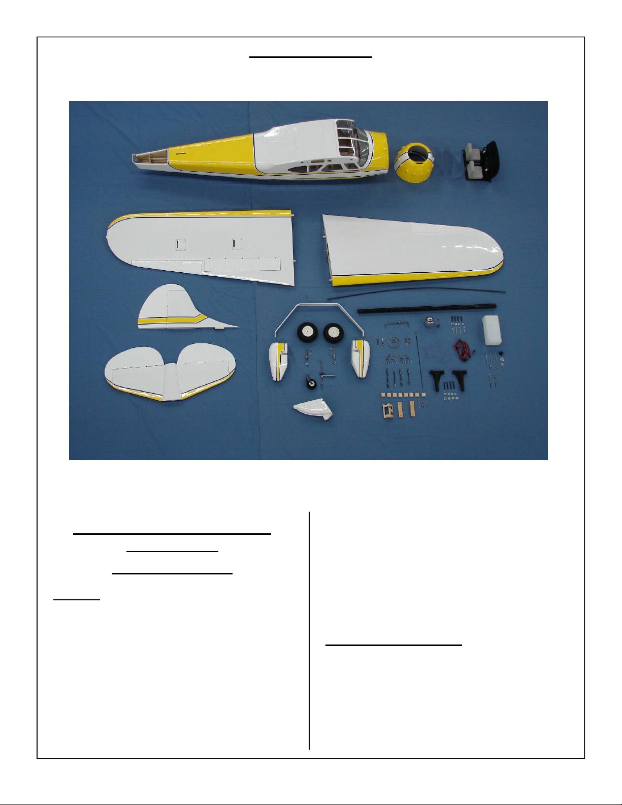
KIT CONTENTS
1.80-30cc Cessna 195 ARF-QB
Materials List
Basic Aircraft Parts
Fuselage Covered with Oracover (4) 8-32 blind
nuts pre-installed in firewall for engine
mounts mounting
(5) 4-40 blind nuts pre-installed for cowling
mounting
(4) 8-32 blind nuts pre-installed for main
landing gear mounting
(1) Removable Top Hatch in place with
(3) 4-40x12mm hex style bolts and
(3) Φ3mm flat washers and three
(3) 4-40 blind nuts
(8) Side Windows 4 each left and right glued
in place
(1) Front Windshield, painted – in place with
(9) T2x5mm PWA screws
(1) Outer plastic tube for flex pushrod for
elevator pre-installed
(1) 3.5(o.d.)x900mm Antenna Tube
preinstalled
(1) White navigation light installed with wir-
ing and connector in place inside fuselage cabin
Left Wing with Aileron, Flap
for the mounting of the control horns
Fuel proof and paint flap Insert
(1) 8-32 blind nut pre-installed for wing
mounting
(5) Small Pin Point Hinges glued for Flap
(5) Large Pin Point Hinges glued for Ai leron
5
– Covered, pre-drilled
Page 6
(1) Front Anti-rotation Pin installed
(1) Rear Anti-rotation Pin installed with pre
drilled cotter pin hole
(1) Red Navigation light installed with wir ing and connector installed at wing root
Right Wing with Aileron, Flap – Covered, pre drilled for the mounting of the control
horns
(1) 8-32 blind nut pre-installed for wing
mounting
(5) Small Pin Point Hinges glued for
Flap
(5) Large Pin Point Hinges glued for
Aileron
(1) Front Anti-rotation Pin installed
(1) Rear Anti-rotation Pin installed and
predrilled cotter pin hole
(1) Green Navigation light installed with
wiring and connector installed at
wing root
Horizontal Stabilizer with elevators
point hinges (not glued)-covered
Elevator connector system in place,
not glued
Pre-drilled for the mounting of the
control horns
Vertical Fin with Rudder
(not glued) - covered
Pre-drilled for the mounting of the
control horns
# 1
(1) Cowl, fiberglass Factory
painted and trimmed,
(5) 4-40x16mm hex bolts for cowl
mounting
(5) #6 bonded washers for cowl
mounting
(5) Φ3mm flat washers for cowl
mounting
# 2
(1) 4mm Aluminum main landing gear -
painted
(4) 8-32x20mm hex bolts for landing
gear mounting
(4) 4mm flat washers for landing gear
mounting
(4) 4mm split ring lock washers for land ing gear mounting
(2) 100m dia. Main Wheels
(2) 5x45mm AL Axle Bolts
(2) M8 lock nuts
(4) 5mm i.d. Wheel Collars with set-
with (4) pin point hinges
with (8) pin
screws
(4) 4-40x14mm hex style bolts for wheel
pants mounting
(4) 3mm flat washers for wheel pants
mounting
(4) 3mm split ring lock washers for wheel
pants mounting
# 3
(2) Wheel Pants – 1 Left and 1 Right –
painted
(4) 4-40 blind nuts installed in the wheel
pants 2 per side
# 4
(1) Tail Wheel Assembly, assembled:
(1) 3mm Steering Wire
(2) 3mm I.D. Wheel Collar with set
screws
(1) 3mm I.D.x10mm O.D.x4mm Nylon
washer
(1) Metal Wheel Fork with 6-32x5mm set
screw
(1) 50mm dia. rubber tail wheel
(1) Aluminum tail wheel mounting plate
#5
(2) 4-40x3” left hand and right hand
threaded pushrods with nuts for ailer ons
2) 4-40x2.5” left hand and right hand
threaded pushrods with nuts for flaps
(1) Wrench for the left hand and right
hand threaded pushrod
(8) 4-40 Ball Links – 4 for ailerons and 4
for elevators
(8) 4-40x16mm hex head bolts
(8) 3mm flat washers
(4) Brass Spacers
(8) 4-40 Lock Nuts
(4) AL Metal Control Horns – 2 left and
2 right
(16) T2.6x12mm Phillips head screws for
control horns mounting
# 6
(1) Flex Pushrod for elevator
(1) 4-40 Ball Link
(1) 4-40 Bolt
(1) Flat Washer
(1) Brass Spacer
(1) Lock Nut
(2) 4-40x1” Threaded Rod
(1) 4-40 Nut
(1) 4-40 R/C Metal Clevis with Spring
# 7
(2) Φ0.8x1150mm Pull-Pull plastic
coated steel Cable
(4) Φ3.5x5mm brass swage tubes
6
Page 7
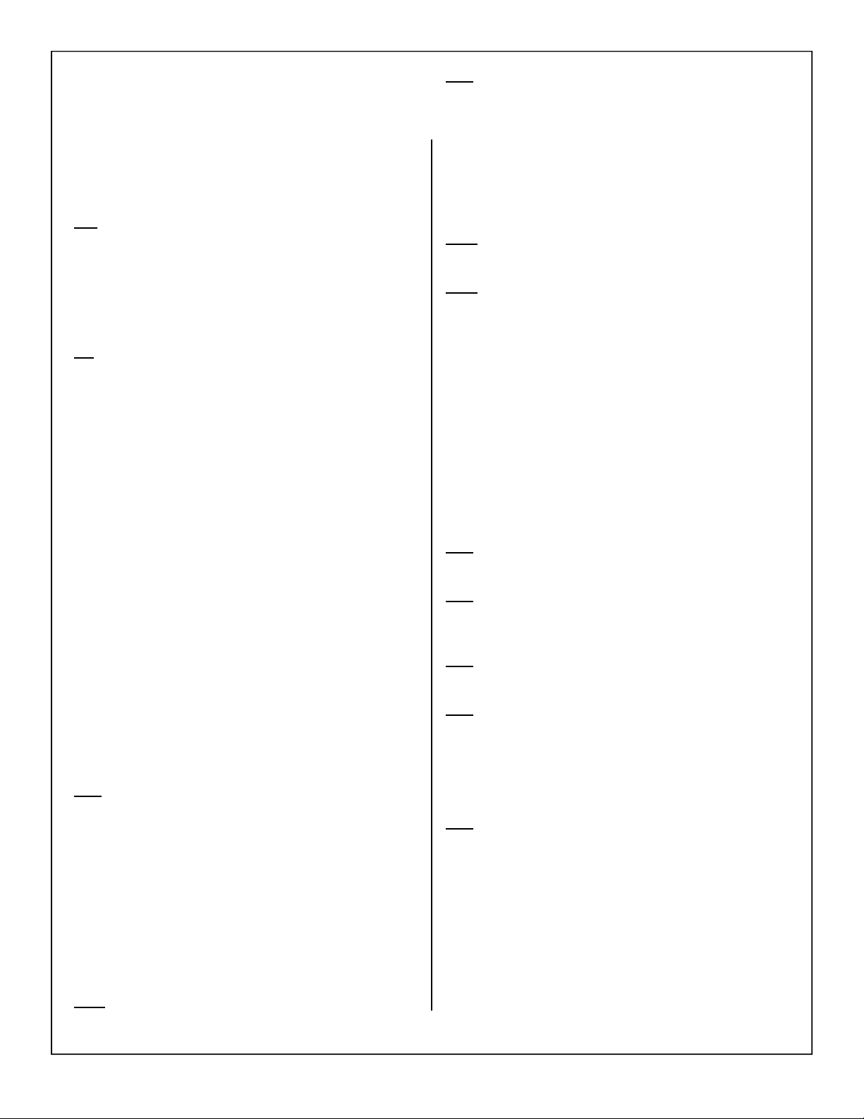
(4) Φ3.5x5mm brass swage tubes
(2) 4-40 R/C Clevises with spring
(4) 4-40 solder coupler with nuts
(2) 4-40 Ball Links
(2) 4-40x16mm hex head bolts
(2) 4-40 lock nuts
(2) Φ3mm flat washers
(2) Brass Spacers
# 8
(1) Plastic Quick Link
(2) Wooden Rod Supports
(1) M2x300mm one end threaded rod
(1) M2 R/C Quick Link
(1) M2x20mm Threaded Rod
(1) 12” Flex Rod with Outer Case
(1) Throttle Servo Tray
# 9
(1)Wooden Mounting Block – For 30cc
DLE Gas Engine
(4) 8-32 x 20mm Hex Head Bolts
(4) 4mm Split Ring Flat Washer
(4) 4mm Flat Washer
(2) 1.20 size engine mounts, 1 left, 1 right
(4) 8-32x35mm hex head bolts for engine
mounts mounting
(4) 4mm flat washers for engine mounts
mounting
(4) 4mm split ring lock washers for
engine mounts mounting
(4) 8-32x30mm hex head bolts for engine
mounting
(4) 8-32 lock nuts for engine mounting
(4) 4mm flat washers for engine
mounting
(4) 4mm split ring lock washers for
engine mounting
(2) Hardwood Thrust Blocks for 2
stroke engine – marked with TOP
or BOTTOM
(2) Hardwood Thrust Blocks for 4
stroke engine – marked with L or R
# 10
(1) 750cc Fuel Tank with Rubber
Stopper (Glow/Gas)
(6) Small Nylon Ties
(2) Fuel Filler Dots
(3) Large Fuel Tubes
(1) 2 feet Large Glow Fuel Line (I.D.
3mm O.D. 5.7mm)
(2) Large Glow Fuel Line for inside
for Tank
(2) Fuel Clunks for inside of Tank
(1) Balsa Tri-stock for behind Fuel
Tank
# 11
(1) Tail Cone
(4) T2.6x12mm PWA Mounting
Screws
# 12
(1) Dash Panel Support - painted
(1) Dash Panel - painted
(1) Pilot Seat
(2) Steering Yokes
(2) Silicon Tubes
(2) Cotter Pins
(1) Felt Lined Cockpit sides
(6) T2.6x8mm PWA screws
# 13
(2) Antennas for the top of the wing
(1) Air Speed Tubes – paint white
# 14
(3) Switch Mounting Trays
(1) Battery Mounting Tray with 4 Holes
and 2 slots
(4) T2.6x8mm PWA screws for battery
mounting tray
(1) 6x100x60mm foam for fuel tank
(2) 8x80x300mm Sponge for receiver
and battery
(4) 356x12.5mm Velcro
(6) 5x500mm Nylon Ties for fuel tank
mounting
(1) Card Stock (8x12”) for the template
for cutting of cowling
(1) Rubber Grommets – 2 each 6,8,10
for fuel line and wire guide
# 15
(1) Custom Throw Meter
# 16
(1) C.G. Buddy
# 17
(1) Aluminum Spinner
# 18
(1) 300x300mm White covering
(1) 300x300mm Bright Yellow covering
Or
(1) 300x300mm White covering
(1) 300x300mm True Red covering
# 19
(4) Flap and Aileron Servo Hatch Covers
(8) Servo Mounting Hardwood Blocks
(24) T2.6x10mm PWA screws for Servo
Hatch and Mounting Blocks
(2) 8-32x25mm Hex Head bolts for wing
mounting
(2) #8 bonded washers
(2) Cotter Pins Rear
(1) 23x19.4x780mm Carbon/Fiberglass
compound wing tube
7
Page 8

# 20 (1) Manual CD
# 21
(1) Wire Loom for the Navigation
Lights – Manual Switch Only
8
Page 9
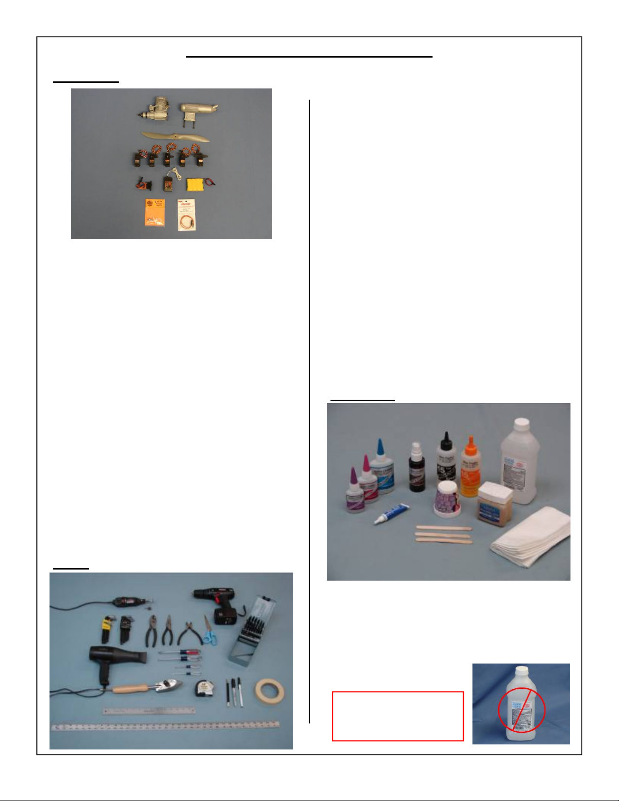
ITEMS NEEDED TO COMPLETE
Hardware:
• 1.60-1.80 Glow– 30cc Gas engine and ignition
• Standard or Pitts style muffler (Pitts Recommended)
• 2 x aileron servos (min 140 in./oz. Torque @ 6
volt, Digital, Metal Geared)
• 2 x flap servos (min 140 in./oz. Torque @ 6 volt,
Digital, Metal Geared)
• 1 x rudder servo (min 180 in./oz. Torque @ 6
volt, Digital, Metal Geared)
• 1 x elevator servos (min 180 in./oz. Torque @ 6
volt, Digital, Metal Geared)
• 1 x throttle servo (Fast / Reliable)
• Servo extensions 2 x 6”, 4 x 18,” 2 x 24”
• 1 x 8 channel receiver (2.4Ghz recommended)
• 1 x receiver battery (min 6.0 volt / 1700ma)
• 1 x ignition battery (min 4.8 volt / 1700ma)
(Gas Only)
• 2 x switches with charge jacks /Rec., Ing
• 1 x Light Battery (4.8 Volt/ 1700ma)
• 1x Switch with charge jack/ Nav Lights
• Allen wrenches US and Metric.
• Dremel cutting disc and sanding drum tool
• Electric drill and selection of bits
Razor saw
•
•
Flat head screwdriver
Hobby heat gun
•
•
Hobby iron and covering sock
• Masking tape
• Modeling knife
• Needle nose pliers or crimping tool
Paper towels
•
•
Pen, pencil or felt tipped marker
• Phillips screwdriver
• Rubbing alcohol
• Ruler and tape measure
• Scissors
• T pins
• Waxed paper
• Wire Cutters
Adhesives:
Tools:
• 15-30 Minute epoxy
• Blue Loctite
• Epoxy mixing cups, mixing sticks, brushes
CA kicker (optional)
•
• Thick, Thin and Medium CA
• Rubbing alcohol
• Wipes
WARNING
Some rubbing alcohols
may attack painted parts.
9
Page 10
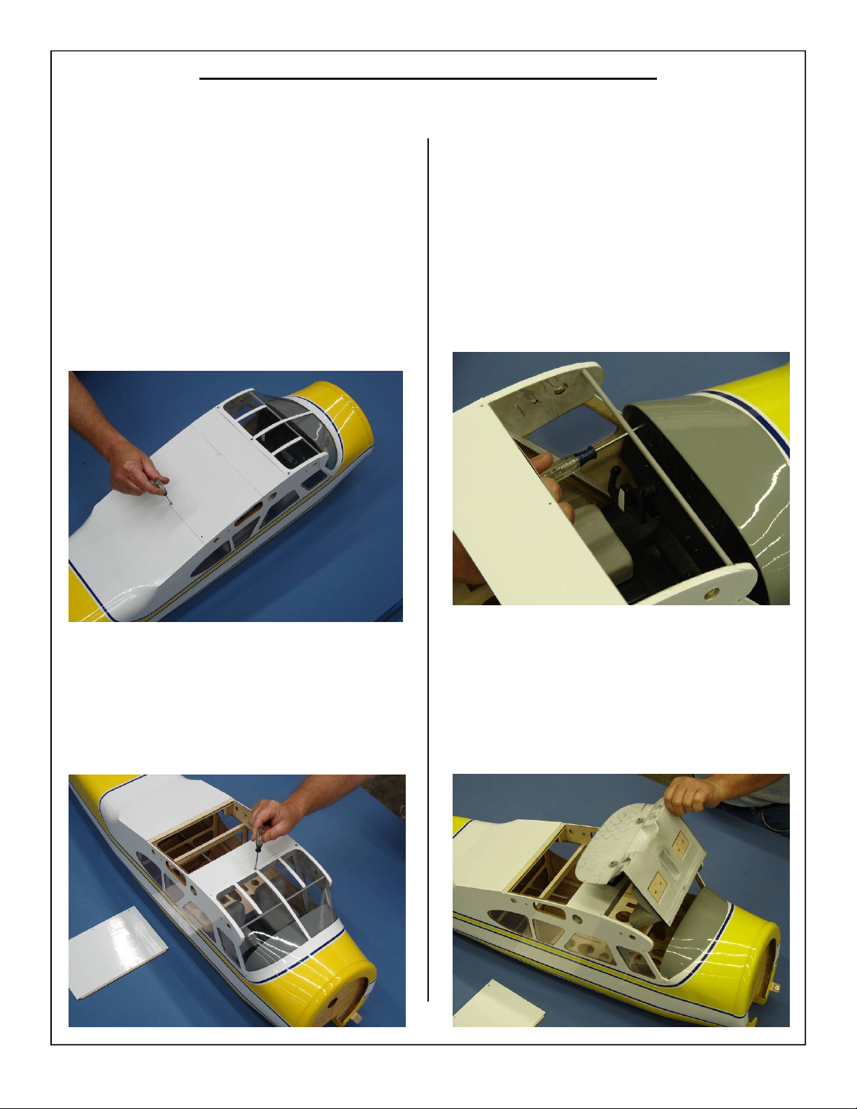
Removing Cockpit Hatch and Instrument Panel
1. Open your kit slowly and take care not to dam-
age any parts of the kit. Remove all parts from
their plastic protective covers for inspection.
Before doing any assembly it is recommended
that the cockpit hatch, canopy, and instrument
panel be removed. This will aid in assembling
the model. These items will be reinstalled when
the rest of the model is finished. Use a Phillips
screwdriver to remove the cockpit hatch as
shown below.
3. Use a Phillips screw driver to remove the mounting screws holding the instrument panel in place.
2. Using a Phillips screw driver remove the canopy
from the fuselage as shown below.
4. Lift the instrument panel out of the fuse through
the canopy opening as shown. Be careful not to
damage the instrument panel or the canopy bracing bar. Also take care not to scratch the felt inside the fuse.
10
Page 11
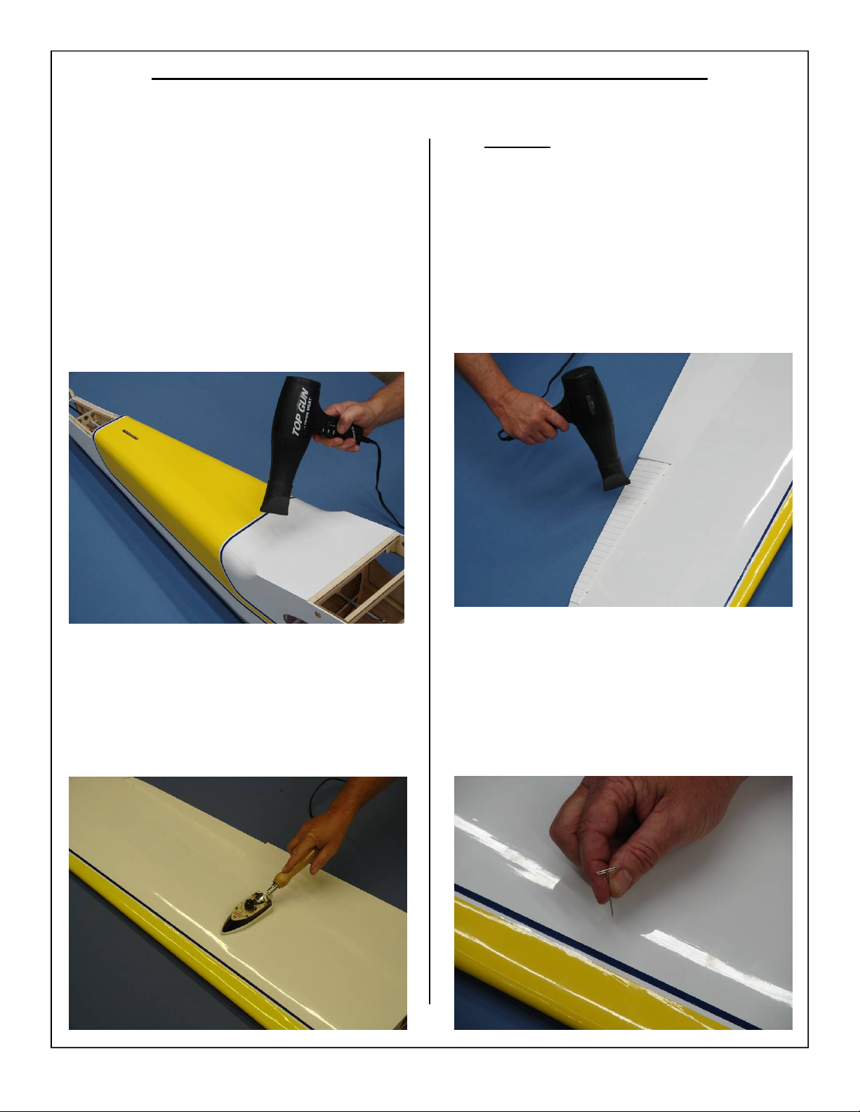
TIGHTENING AND RE-SHRINKING THE COVERING
1. Before doing any assembly or installation of any
decals it is very important to re-shrink or retighten the already applied covering. Due to the
shipping process, heat and humidity changes
from different climates, the covering may become lose and wrinkle in the sun. If you take the
time to re-tighten the covering, you will be rewarded with a long lasting beautifully covered
model.
3. DO NOT use a heat gun on the corrugated con-
trol surfaces. Heat applied directly to these surfaces will cause the material to deform and bubble.
2. Using your covering iron with a soft sock, gently
apply pressure and rub in the covering. If any
bubbles occur, your iron may be to hot. Reduce
heat and work slowly.
4. If bubbles persist, use a small pin to punch holes
in the bubble to relieve trapped air and reheat.
11
Page 12
CHECKING SEAMS AND COLOR OVERLAPS FOR GOOD SEAL
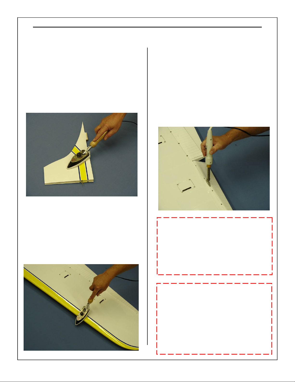
1. Go over all seams and color overlaps with your
sealing iron.
Note: Even if your models covering has no wrin-
kles out of the box it is still very important to go
over all seams and overlaps to make certain they are
sealed securely. This is especially important at the
leading edges of the wings and stabs. We recommend checking the covering after each flying session.
3. Use a small trim iron to iron out the wrin-
kles in the hinge lines. It is important to
keep the covering sealed down in this area.
Note: Take care not to apply to much heat
around any plastic or corrugated parts.
2. Use your covering iron to ensure all edges,
seams, and color overlaps are securely sealed.
IMPORTANT:
It is the responsibility of the purchaser /
operator to check the covering seams and
overlaps for security and a good seal.
Aeroworks is not responsible for failure of
covering seams or overlaps during flight.
Note: If covering continues to lift apply a small
amount of thin CA underneath the covering.
Then using a clean rag apply pressure to secure.
One of the most important tools in your
flight box is a roll of clear tape. This can be
used at the field for fast and easy repairs of
the covering. Then once you have finished
flying the covering can be permanently
repaired.
12
Page 13
Ultracote™ Colors
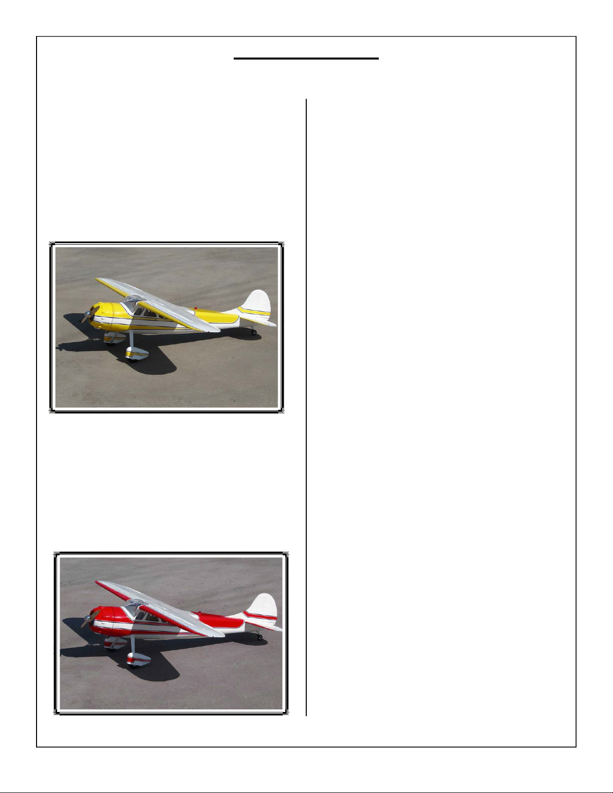
1. Your model is covered with Ultracote™ covering.
In case of repairs, the colors are:
Yellow/Blue Scheme
Bright Yellow #872
Midnight Blue #885
White #870
2. Red/Black Scheme
True Red #866
Black #874
White #870
13
Page 14
WING ASSEMBLY
Aileron/Flap Servo Installation
1. The ailerons/flaps have been pre-hinged and
glued to the wing panels and are ready for flight.
No other steps are necessary for hinging.
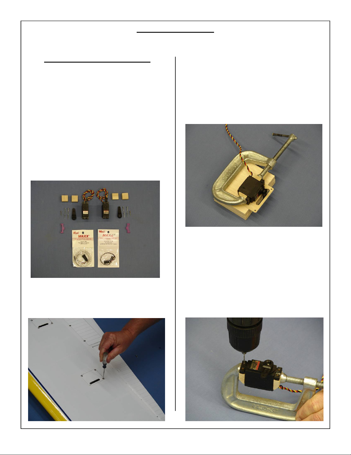
Gather (1) wing panel, (1) aileron servo, (1) Flap
Servo (8) servo mounting screws, (4) Wood
screws for mounting blocks, (2) 1 1/4” servo
arm , (2) safety clip (1) 6” servo extension (1)
18” Servo Extension and (4) Servo Mounting
blocks as shown below for preparation of the
servo installation.
3. Use a C-Clamp to hold the servo mounting
blocks to the servo as shown. Use a block of
wood to elevate the servo mounting hatch as
shown.
2. Using a Phillips screw driver remove the aileron
servo mounting hatch as shown below.
4. Use a 1/16” drill bit to drill the mounting holes
for the servo mounting screws as shown.
14
Page 15
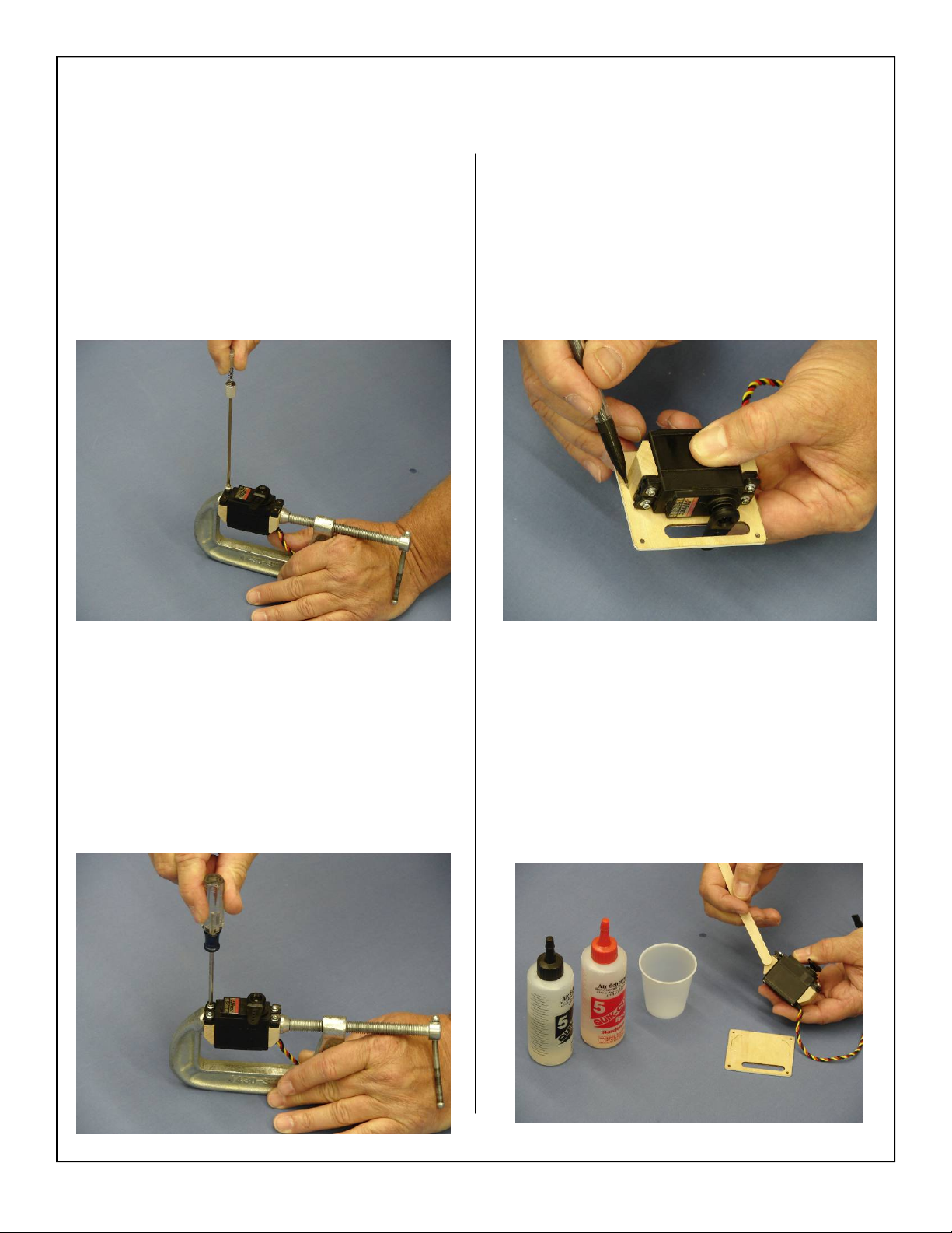
5. A hand drill may also be used to drill through
the blocks as shown below.
7. Mark the location of the servo mounting blocks
onto the servo hatch as shown below. Make sure
the servo arm is positioned in the opening as
shown below.
6. Install the servo mounting screws as shown.
8. Use 5 to 15 minute epoxy to glue the servo
mounting block to the servo hatch. Be careful
not to get any epoxy on the servo case.
15
Page 16
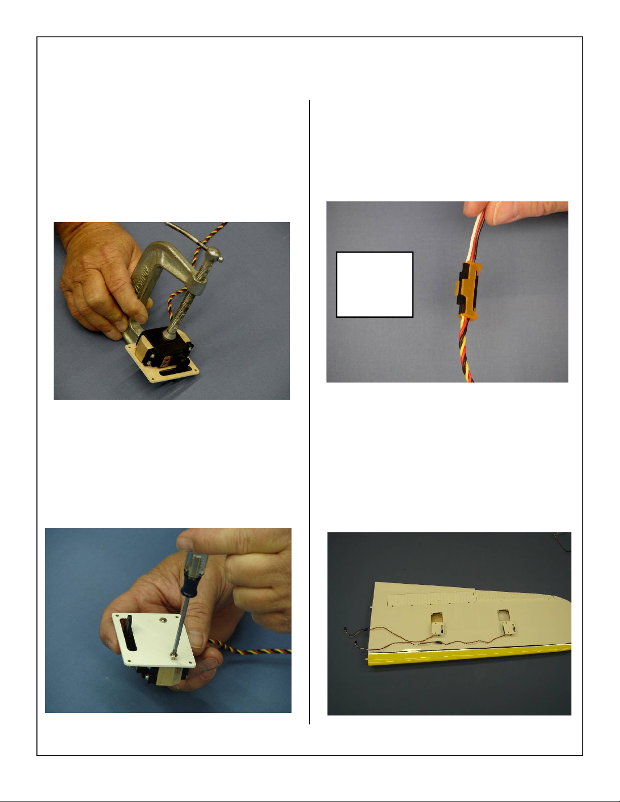
9. Use a C-Clamp to hold the servo against the
hatch until the epoxy fully cures. Use a piece of
balsa or foam on the bottom of the C-Clamp to
avoid crushing the servo mounting hatch.
12. Attach the 6” and 18” extension to the servo
lead and secure with Aeroworks Safety Clip.
Ensure the connectors will not come apart from
vibration or light tension.
Safety Clips
Available
from
Aeroworks
10. For added strength install provided wood screws
into the servo mounting blocks as shown below.
This will ensure that the block will be unable to
come loose.
11. Repeat steps for the 3 remaining servos.
13. Layout the servos as shown below. Install the
extensions at this time and double check extension length.
16
Page 17
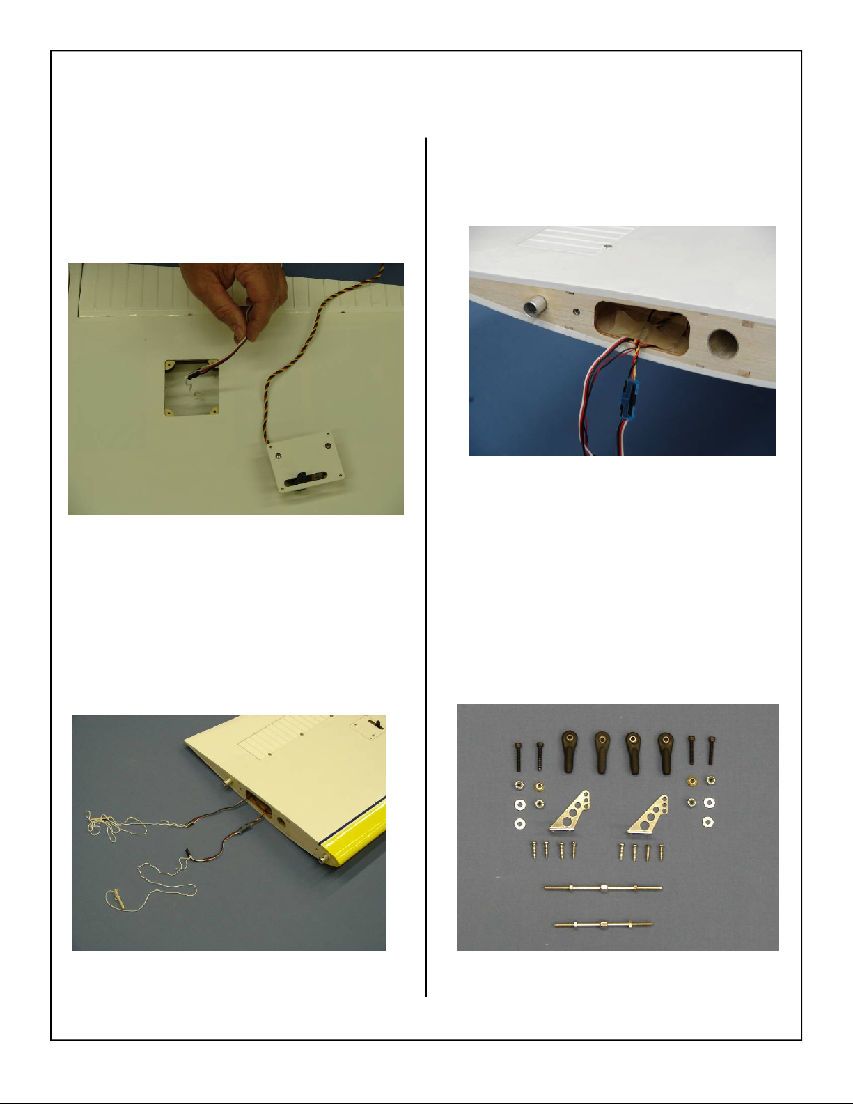
14. Fasten the pull string from the servo hole to the
male plug of the servo extension.
15. Draw the servo extension through the wing and
pull through the wing root rib.
16. Taping servo lead to the inside of the wing panel
will help to prevent leads from dropping back
inside of wing panel during transportation.
17. Gather the aileron and flap control linkage parts
as shown below. (1) 3” pushrod aileron, (1) 2.5”
Pushrod flap (4) 4-40 ball link assemblies, (2)
brass spacers, (4) flat washer, (2)control horns,
and (8) wood screws for each wing panel.
17
Page 18
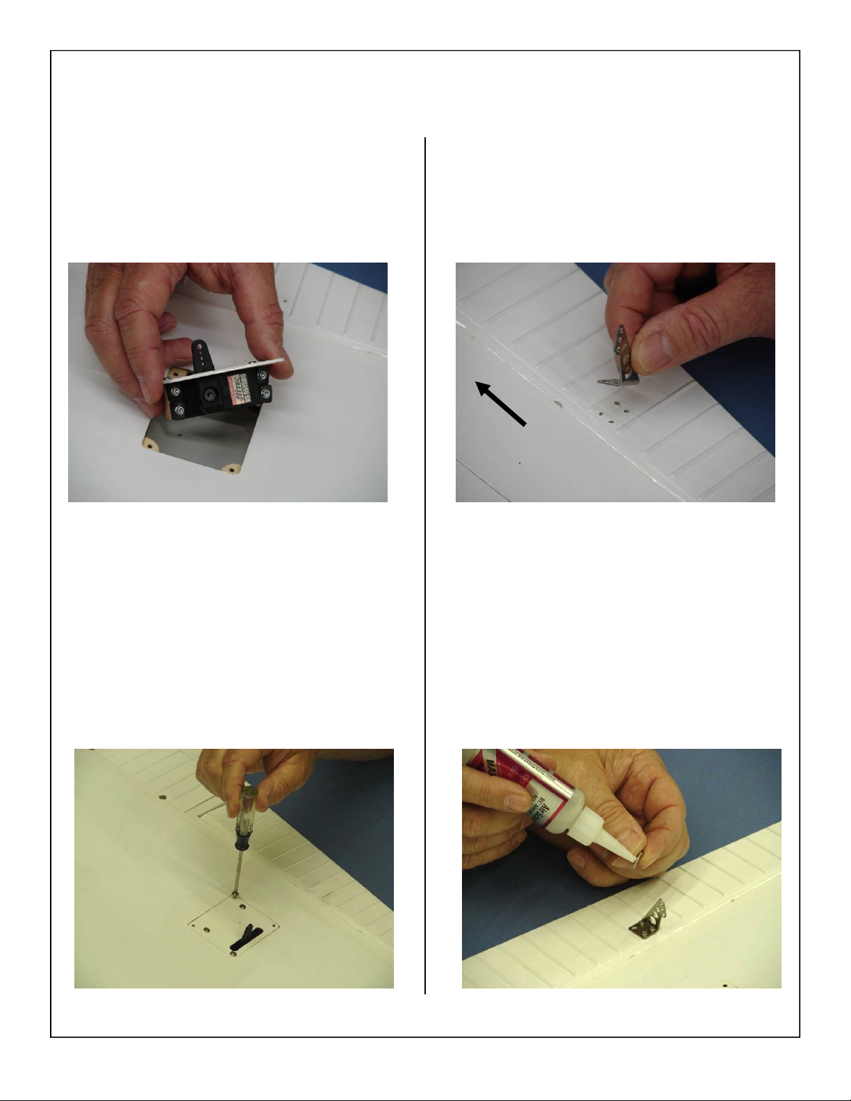
18. Install the servo hatch back in the wing as
shown. The servo arms will be towards the leading edge of the wing.
19. Reinstall the 4 mounting screws as shown below. Be careful not to strip the wood the screws
go into.
20. Place the control horns over the predrilled
mounting holes.
Wing Root
21. Use a drop of thick CA glue on each screw to
prevent screws from loosening due to vibration
as shown.
18
Page 19
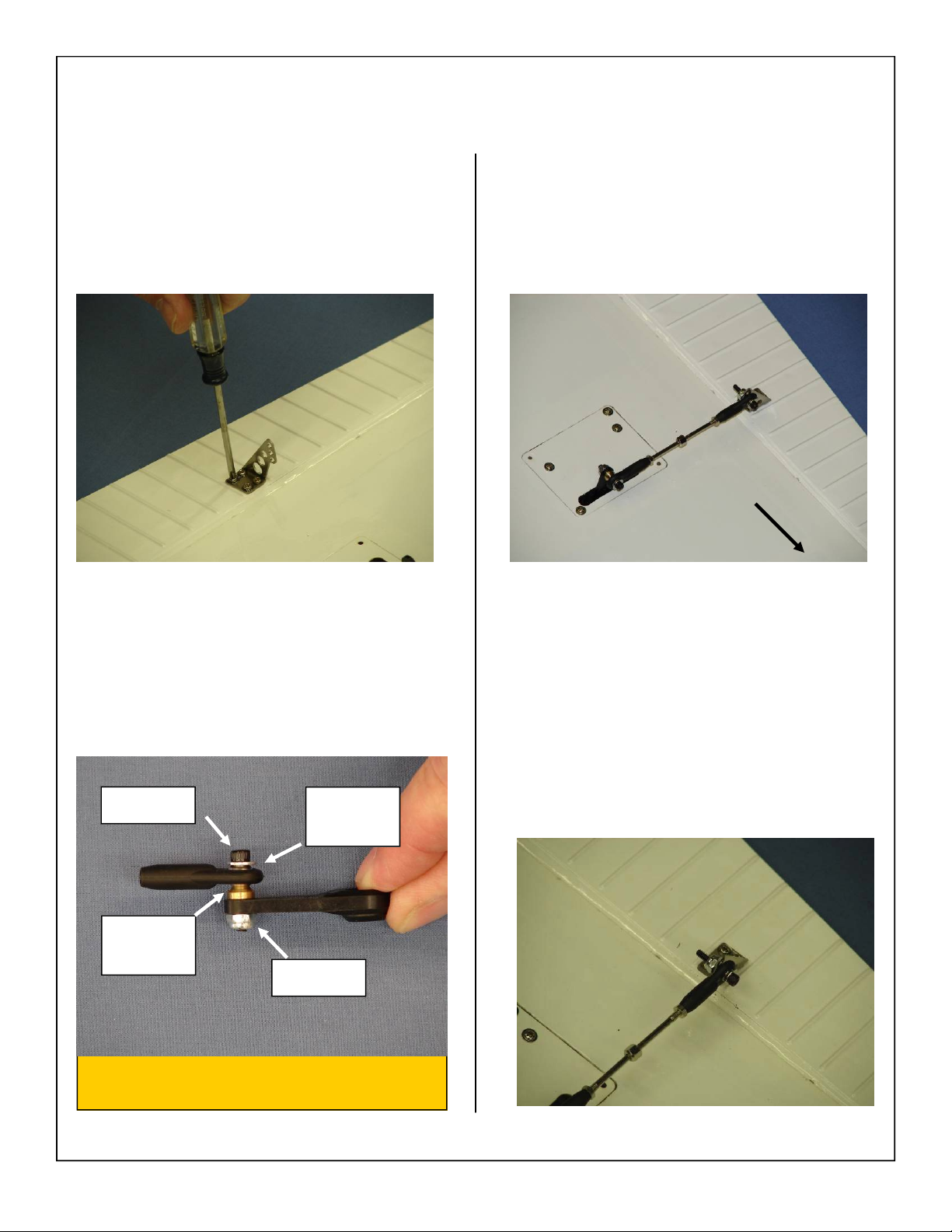
22. Securely fasten the control horn to the aileron
with four wood screws.
23. Correct installation of ball link to servo arm
shown below.
Note: Flat washer will prevent ball link from
coming loose from brass ball.
24. Install pushrod as shown below. The ball links
should be positioned towards the wing tip on
both the servo arm and pushrod.
Wing Tip
25. Correct installation of ball link to control horn
shown below.
4-40 Bolt
Flat
Washer
Brass
Spacer
Lock Nut
Note: Flat washer prevents ball link from
coming off brass ball.
19
Page 20
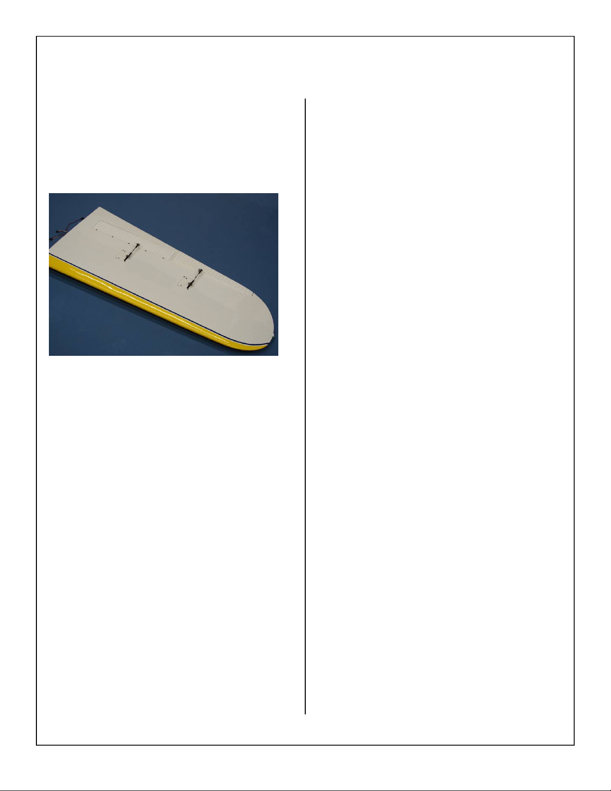
26. Finished wing assembly shown below.
27. Repeat all the above steps for the other wing.
20
Page 21
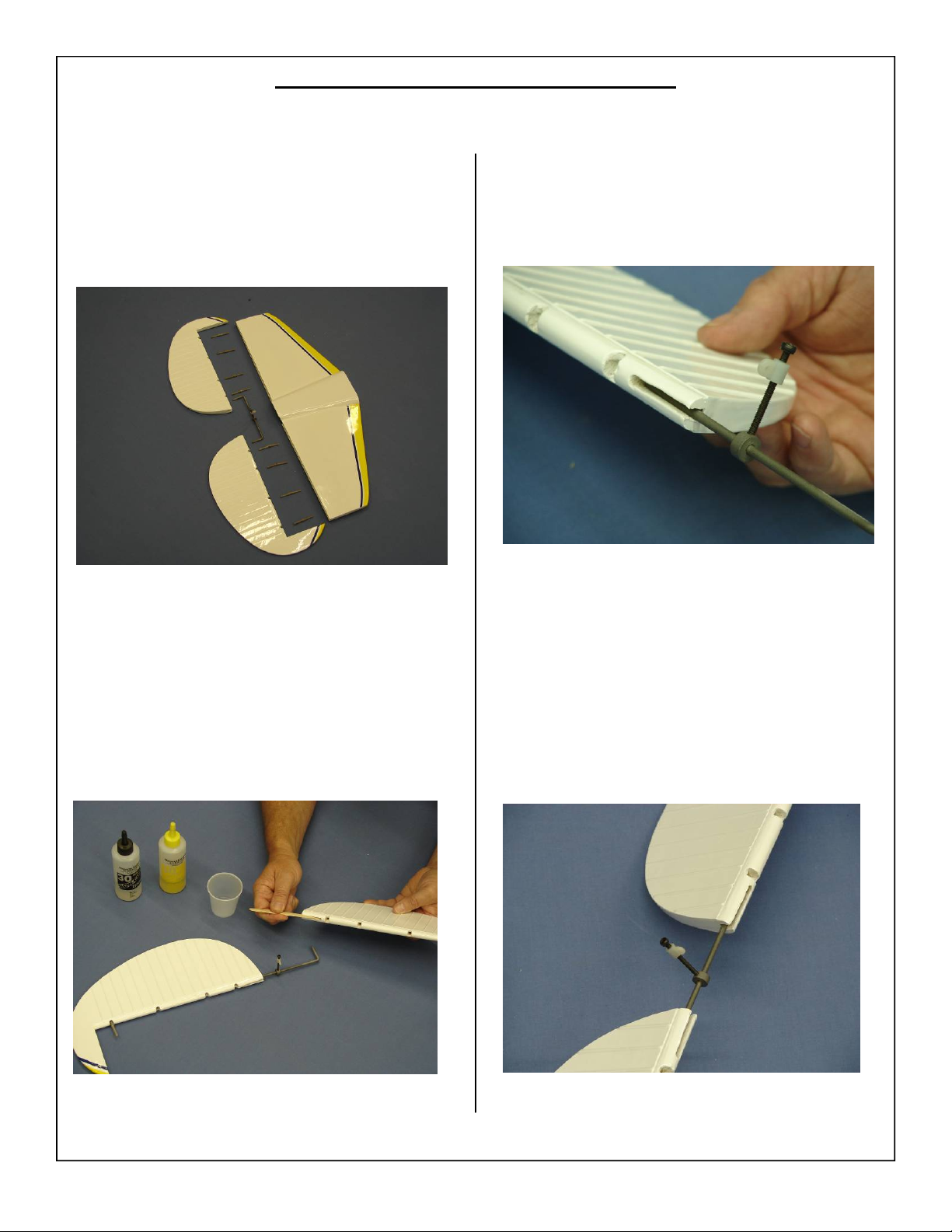
ST AB AND ELEV ATOR ASSEMBLY
Elevator Installation
1. Gather the horizontal stab, elevator assembly,
elevator “U” rod and 8 elevator hinges as shown
below.
2. Mix epoxy in mixing cup and use a tapered stick
to apply the epoxy inside the pre-drilled holes in
the leading edge of the elevator. Apply epoxy to
one side of the elevator “U” Rod and insert the
“U” Rod completely into the hole. Ensure the
“U” Rod is fully inserted and straight in the elevator before epoxy cures. Wipe away excess
epoxy with alcohol wetted wipes.
3. Ensure the control rod is on the bottom of the
elevator assembly as shown.
4. Repeat steps for the remaining elevator half and
set elevators aside on a flat surface. Insure that
the elevators are aligned with each other before
the epoxy fully cures.
21
Page 22
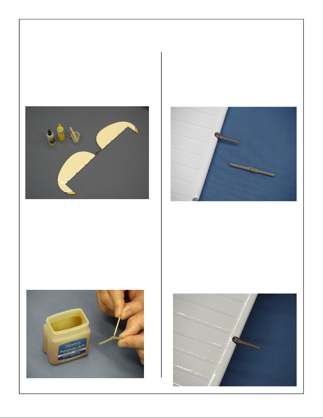
5. Gather the elevator assembly, 30 minute epoxy,
mixing stick, and mixing cup as shown below.
7. Install hinge in the predrilled hole as shown. The
knuckle portion of the hinge should be embedded into the elevator as shown.
6. Prep all hinges for installation by applying Vaseline petroleum jelly or light oil to the hinge joint.
This ensures no epoxy gets into the hinge during
assembly.
8. Trial fit all hinges prior to gluing as shown below.
22
Page 23
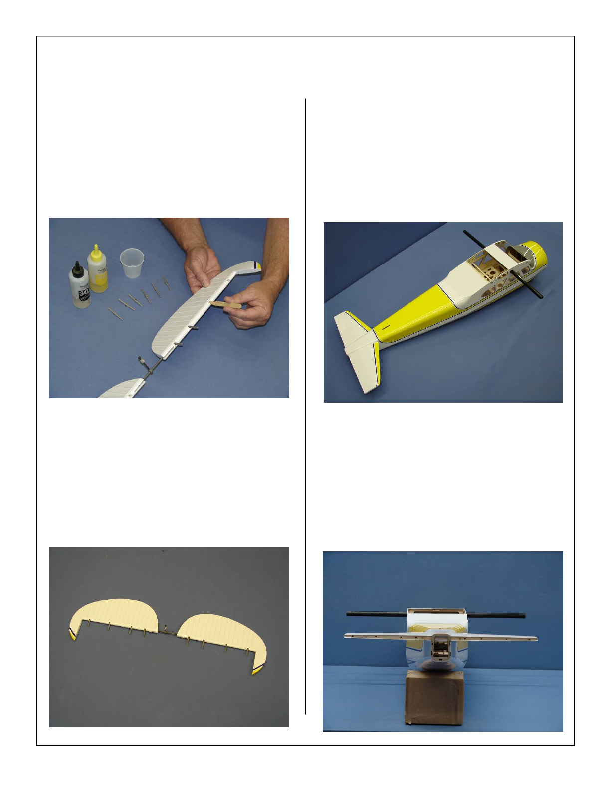
9. Mix epoxy in mixing cup and use a tapered stick
to apply the epoxy inside the pre-drilled holes in
the leading edge of the elevator. Apply epoxy to
each hinge and install in elevator.
11. Gather the fuse, horizontal stab, and wing tube
as shown below.
10. Set the elevator assembly aside and allow the
hinges to fully cure. Check the alignment of the
hinges before the glue fully cures to ensure they
are straight and move freely.
12. Install wing tube in fuse and place stab in the
stab saddle as shown. Check the alignment of
the horizontal stab against the wing tube. Some
shimming or light sanding may be necessary for
a perfect alignment.
23
Page 24
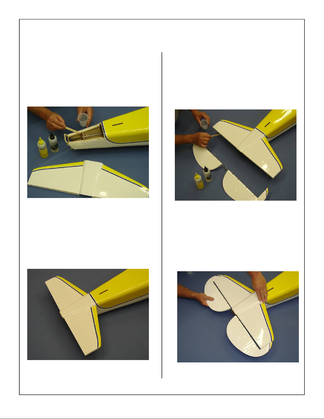
13. Mix 30 minute epoxy in mixing cup and use a
stick to apply the epoxy to the stabilizer mounting rails as shown. Install the stab onto the stabilizer saddle. Use alcohol wetted wipes to remove
any excess epoxy.
15. Mix epoxy in mixing cup and use a tapered stick
to apply the epoxy inside the pre-drilled holes in
the trailing edge of the elevator. Apply epoxy to
each hinge.
14. Allow epoxy to fully cure before moving on to
the hinging of the elevator.
16. Slide hinges into the predrilled holes in the elevator as shown. Make sure the hinges are pushed
in all the way to avoid any gaps in the hinge line.
24
Page 25
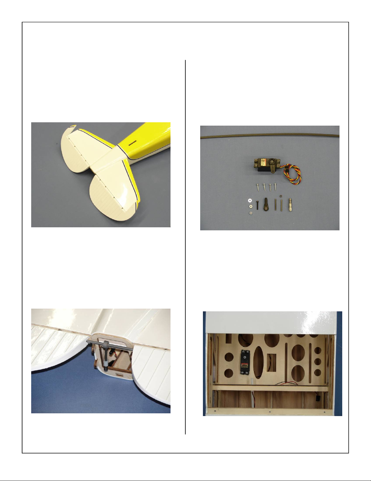
17. Before hinges fully cure check the hinges for
proper throw as shown below.
19. Gather the elevator servo, servo mounting
screws, 1 1/4” servo arm, 4-40 ball link with
hardware, 4-40 clevis, 4-40 threaded inserts and
the elevator pushrod as shown below.
18. Ensure that the elevator control rod is positioned
as shown below.
20. Install elevator servo in the fuselage cabin area
as shown below.
Note: The servo output arm will go towards the front
of the fuselage as shown below.
25
Page 26
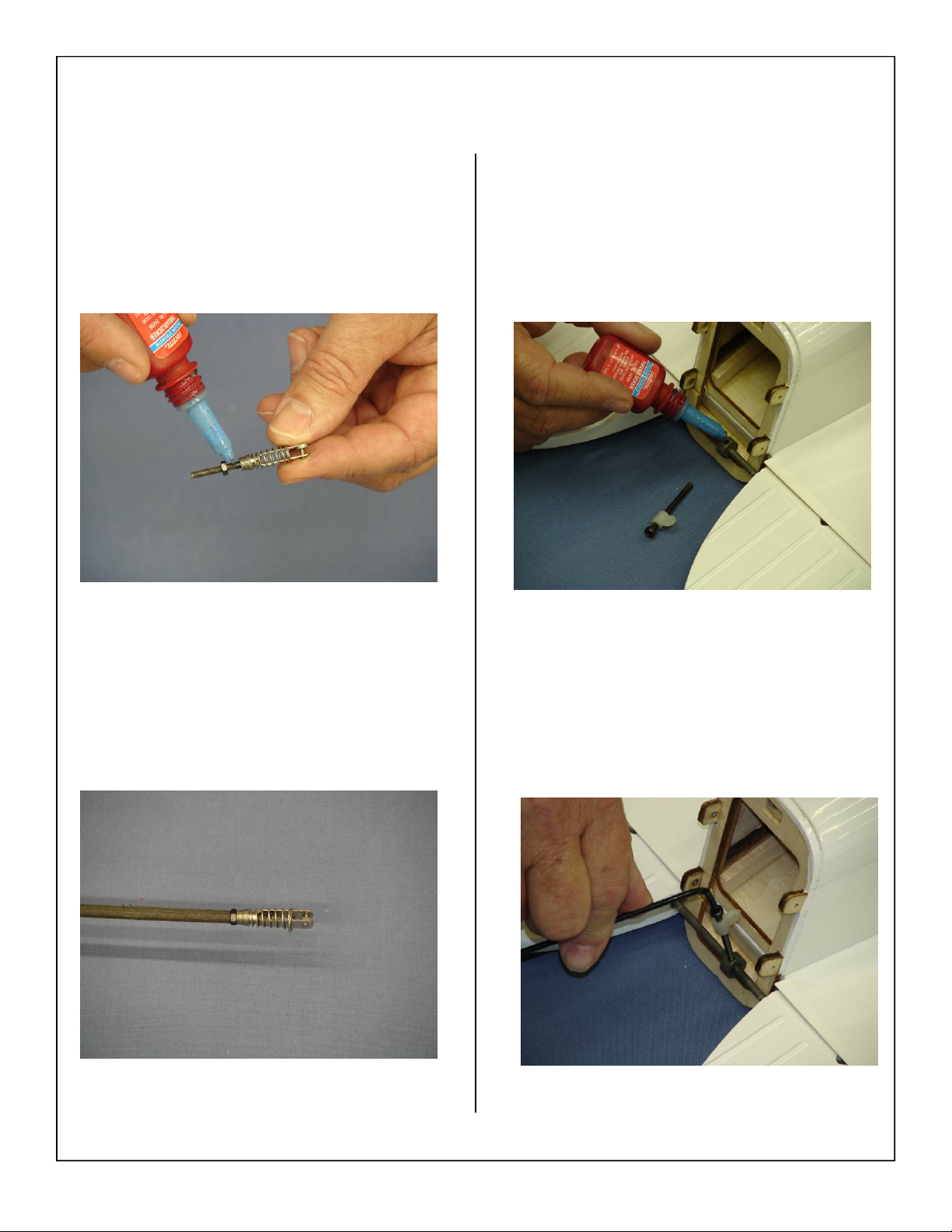
21. Install the 4-40 clevis and lock nut on the 4-40
threaded insert as shown. A drop of blue loctite
may be applied to keep the clevis from loosening
in flight.
23. Remove the elevator control rod and apply a
small drop of blue loctite as shown below.
22. Install the threaded insert into the pushrod as
shown below. A small drop of thick CA may be
used to secure the threaded insert in the pushrod.
24. Reinstall the elevator control rod as shown.
26
Page 27
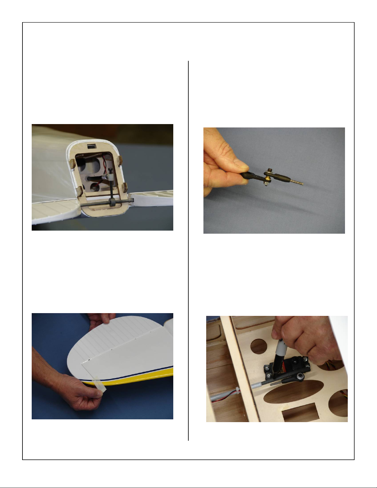
25. Slide the elevator pushrod into the preinstalled
guide tube and connect to the elevator control
rod.
27. Attach the 4-40 ball link to the elevator servo
arm as shown below. Install the 4-40 threaded
insert into the ball link at this time.
26. Tape the elevator counter balance at neutral as
shown below.
28. Place the servo arm on the servo and mark the
location of the threaded insert to thread into the
pushrod.
27
Page 28
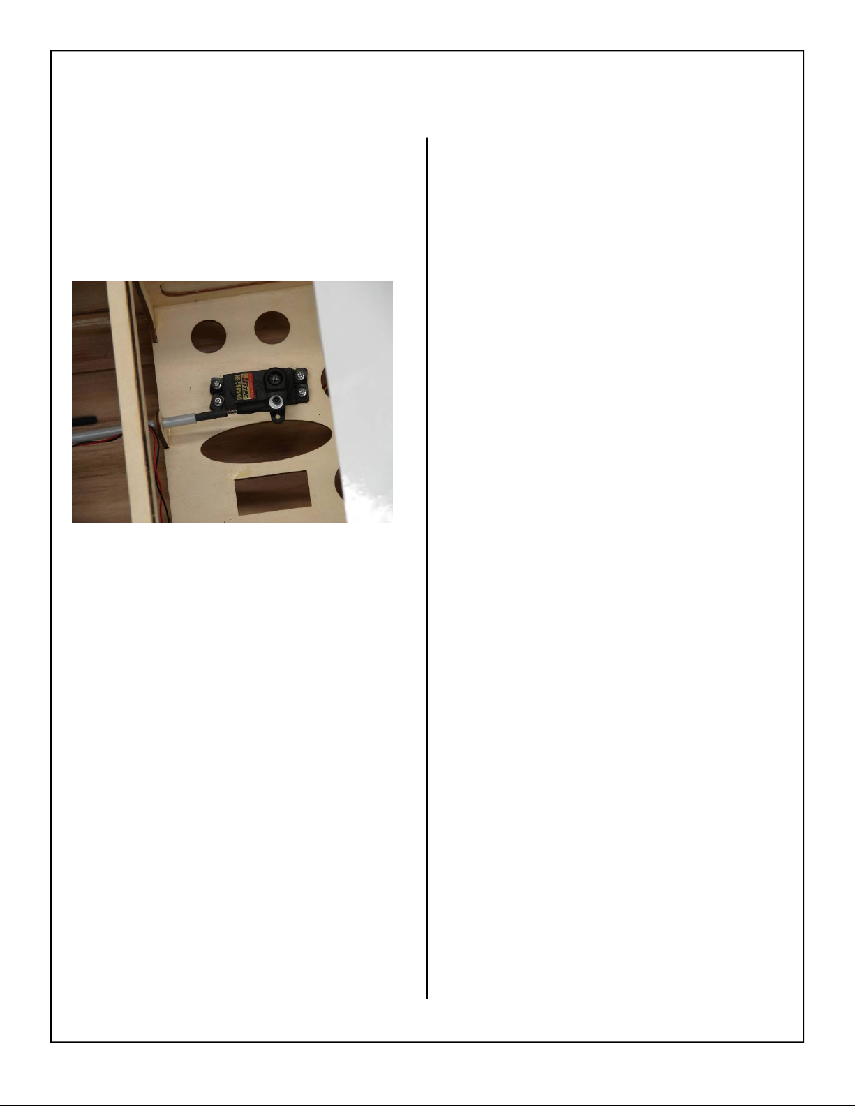
29. Install the threaded insert into the pushrod as
shown below. A small drop of thick CA may be
used to secure the threaded insert in the pushrod
28
Page 29
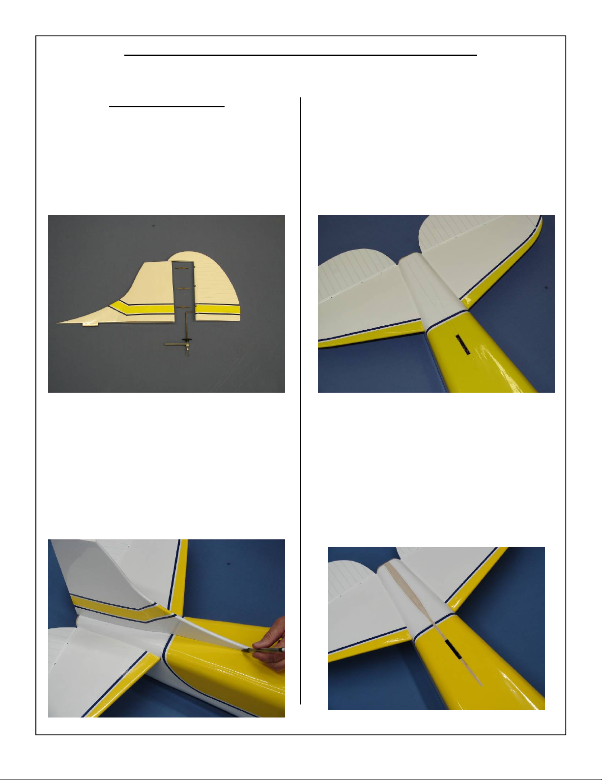
RUDDER AND PULL – PULL CABLE ASSEMBLY
Rudder Installation
1. Gather the vertical fin, rudder, three hinges, and
rudder drive assembly as shown.
3. Remove the vertical fin and ensure the lines
marked in the previous step are visible.
2. Mark the location of the vertical fin on the top of
the fuse as shown.
4. Remove the covering from the top of the fuse
using a hobby knife. Be careful not to cut to
deep into the sheeting as this can weaken the
structure.
29
Page 30
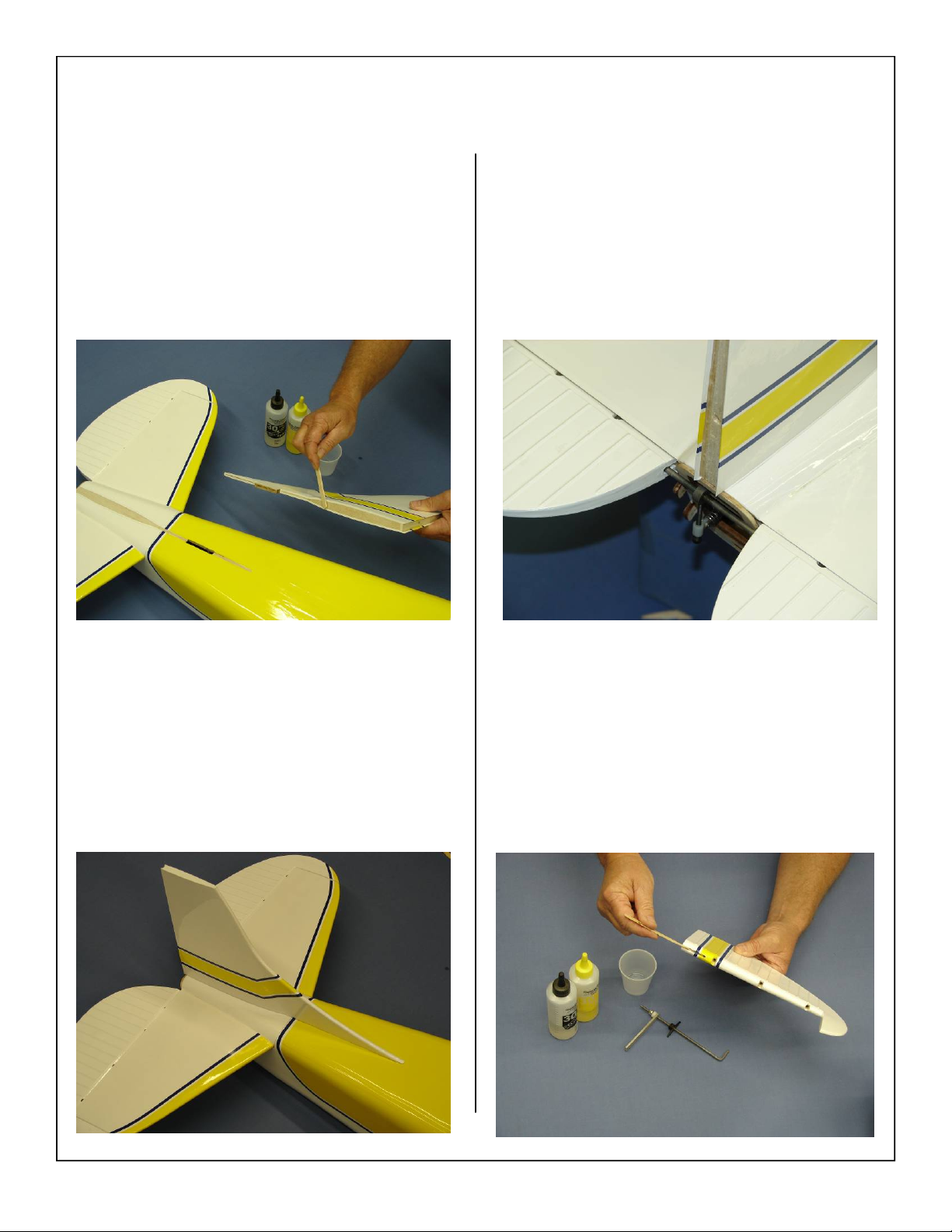
5. Mix epoxy in mixing cup and use a stick to apply the epoxy to the bottom of the vertical fin as
shown.
7. Correct position of fin shown below. Ensure that
the trailing edge of the fin is flush with the trailing edge of the stab.
6. Carefully install the fin back on top of the fuse
as shown below. Wipe away any epoxy with
alcohol wetted wipes. Allow epoxy to fully cure
before moving on to the next step.
8. Glue the rudder drive assembly into the pre cut
slot in the rudder using epoxy as shown below.
30
Page 31
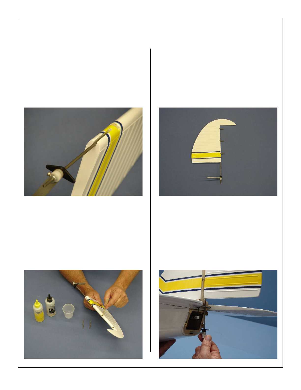
9. Ensure the rudder drive assembly is positioned
correctly and all the way in the pre cut slot before the glue cures.
11. Set the rudder assembly aside and allow the
hinges to fully cure. Check the alignment of the
hinges before the glue fully cures to ensure they
are straight.
10. Mix epoxy in mixing cup and use a tapered stick
to apply the epoxy inside the pre-drilled holes in
the leading edge of the rudder. Apply epoxy to
one end of each hinge.
12. Trial fit the rudder and the rudder drive assembly as shown.
31
Page 32
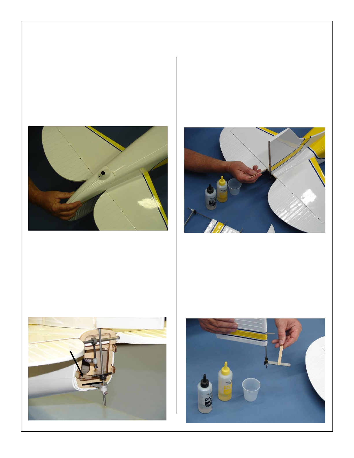
13. Test fit the tail cone assembly as shown below.
The rudder drive assembly rod should be centered in the pre cut tail wheel exit hole.
15. Mix epoxy in mixing cup and use a tapered stick
to apply the epoxy inside the pre-drilled holes in
the trailing edge of the vertical fin Apply epoxy
to each hinge.
14. Remove the tail cone assembly and mark the tail
wheel bracket where it exits the fuse. This will
allow you to apply glue in the correct area. Make
sure the rod is strait and wont bend or pull on the
rudder.
Mark Here
16. Apply epoxy to the tail wheel bracket as shown.
32
Page 33
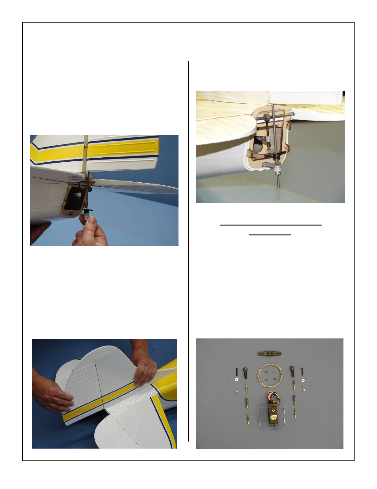
17. Carefully slide the hinges in rudder into each
hinge hole and against the trailing edge of the
fin. Slide the tail wheel bracket into position and
align to mark previously drawn. Wipe away
excess epoxy with alcohol wetted wipes.
18. Ensure there is no gap between fin and rudder.
Allow epoxy to fully cure. Check you have full
rudder deflection before epoxy fully cures.
19. Finished rudder/rudder drive assembly shown
below.
Pull-Pull and Rudder Servo
Installation.
1. Gather the rudder control linkage parts shown
below.(1) Rudder servo (1) 2 3/4” double output
servo arm (4) servo mounting screws (2) rudder
cables, (2) ball link assemblies, (2) flat washers,
(2) Brass Spacers (2) 4-40 clevises (4) threaded
couplers with lock nut, and (4) brass swaging
tubes.
33
Page 34
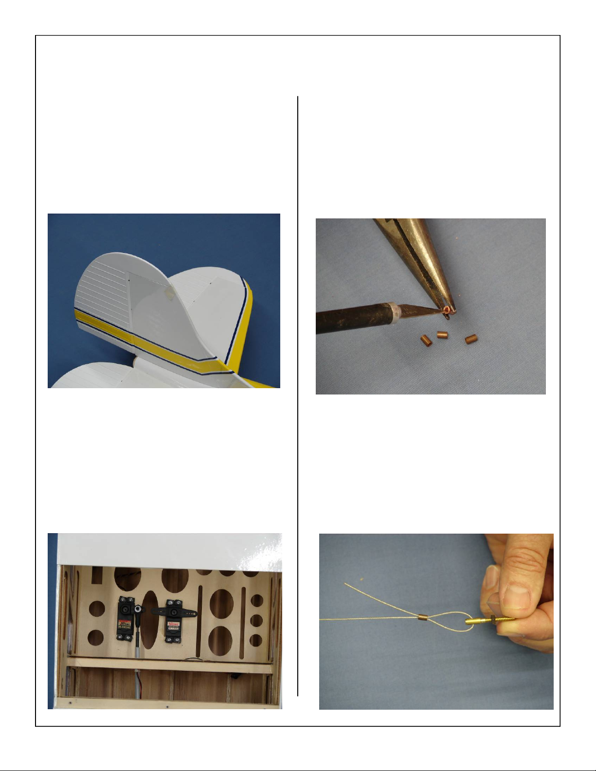
2. Tape the rudder balance tab to the top leading
edge of the vertical fin in the neutral position as
shown. This ensures the rudder is straight when
the cables are attached.
4. Using an X-ACTO knife clean away any burrs
from brass swags. This will allow the rudder
cable to pass through brass swage easily.
3. Install the rudder servo in the servo cutout with
the output shaft to the front.
5. Thread cable through brass swage and the
threaded coupler as shown.
34
Page 35
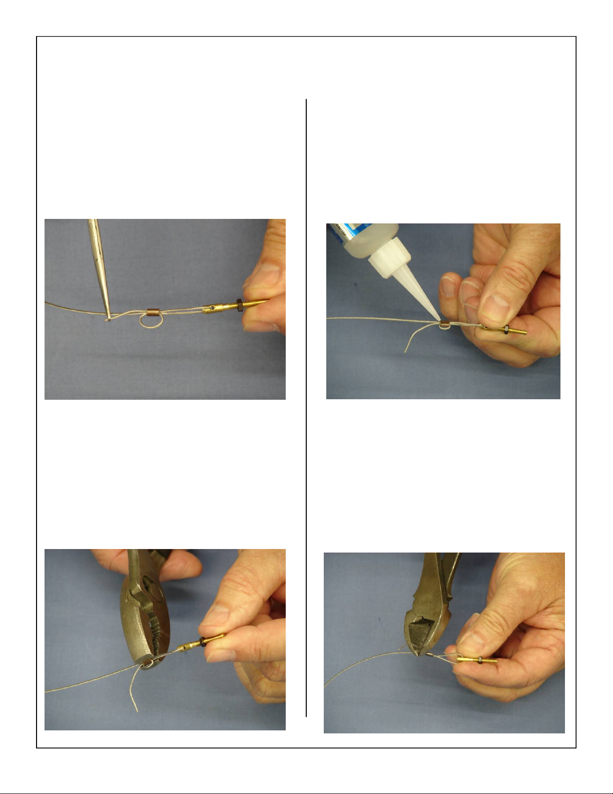
6. Loop the cable back through the brass swage
tube and pull tight.
8. A drop of thin CA may be applied to the swage
tube to help secure the cable.
7. Crimp the brass swage tube with a crimping tool
or pliers.
9. Cut off excess cable as shown.
35
Page 36
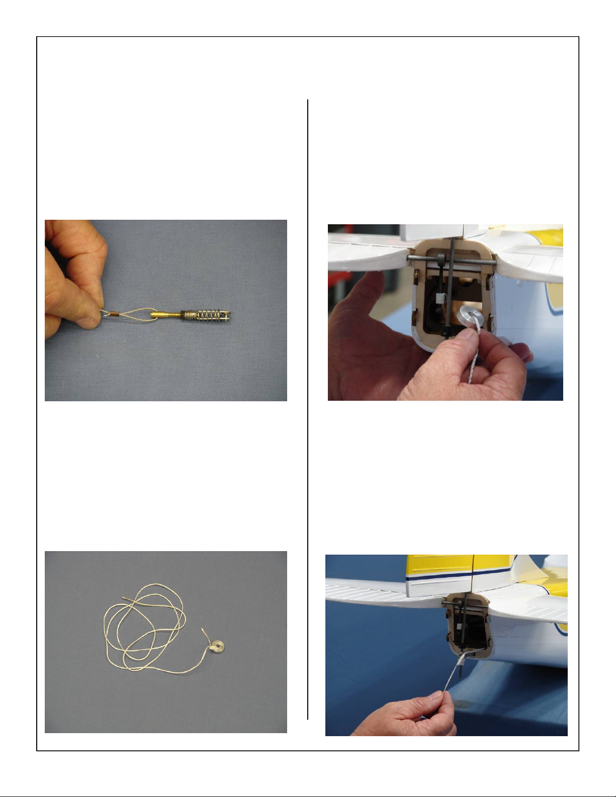
10. Thread clevis onto the threaded coupler as
shown.
12. Drop the weight into the rear of the fuse. Turn
the fuse on its nose and allow the weight with
the string attached to drop into the fuse.
11. Attach a weight to a piece of string as sown below. This will be used to pull the pull pull cables
through the fuse.
13. Tape the end of the cable without the clevis to
the string. Carefully feed the cables through the
fuse making sure they do not become tangled.
36
Page 37
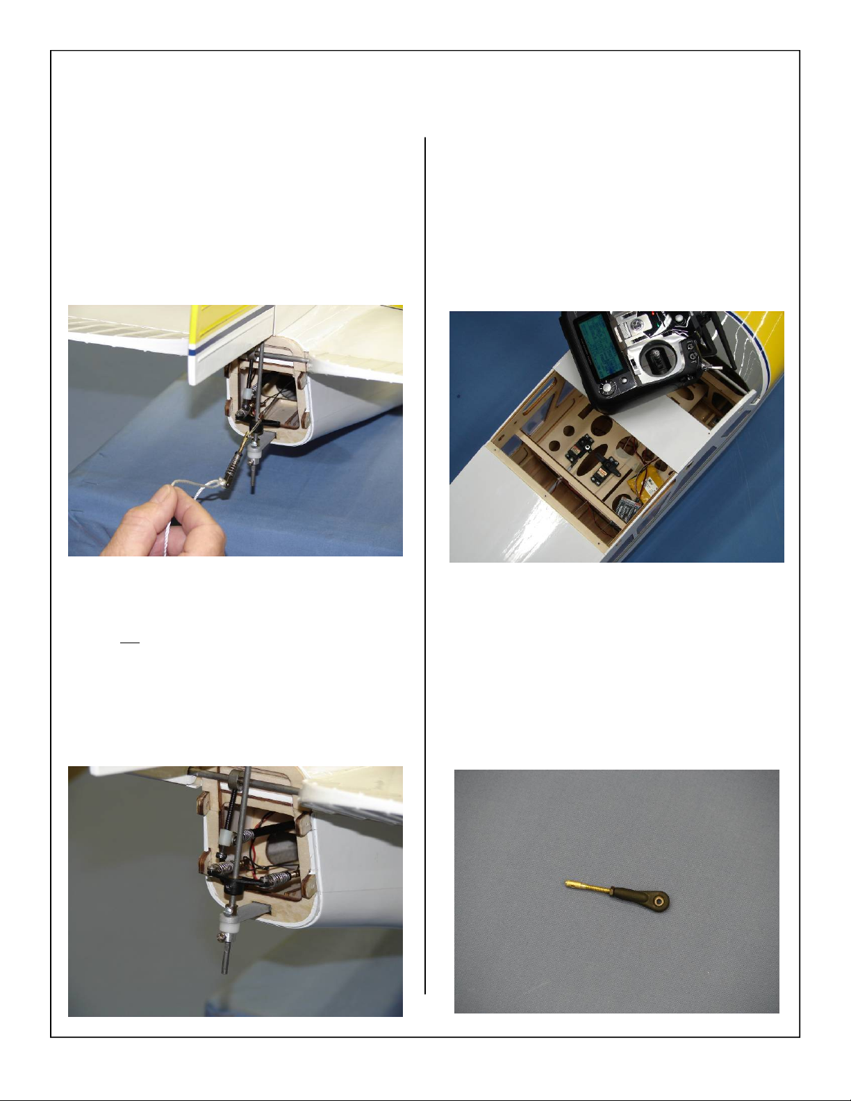
14. Remove the string from the clevis as shown.
16. Plug the rudder servo into the rudder channel of
the receiver and power up. Turn on transmitter
to center rudder servo. Ensure servo trim and
sub trims are centered.
Note: On metal geared servos use blue Loctite for
all Servo arm mounting screws.
15. Attach the pull pull cables to the rudder drive
assembly as shown below. Ensure that the cables
are not
crossed inside the fuse.
17. Install the ball link onto the threaded pull pull
coupler as shown below. Allow enough of the
coupler to be left unthreaded for final adjustment.
37
Page 38
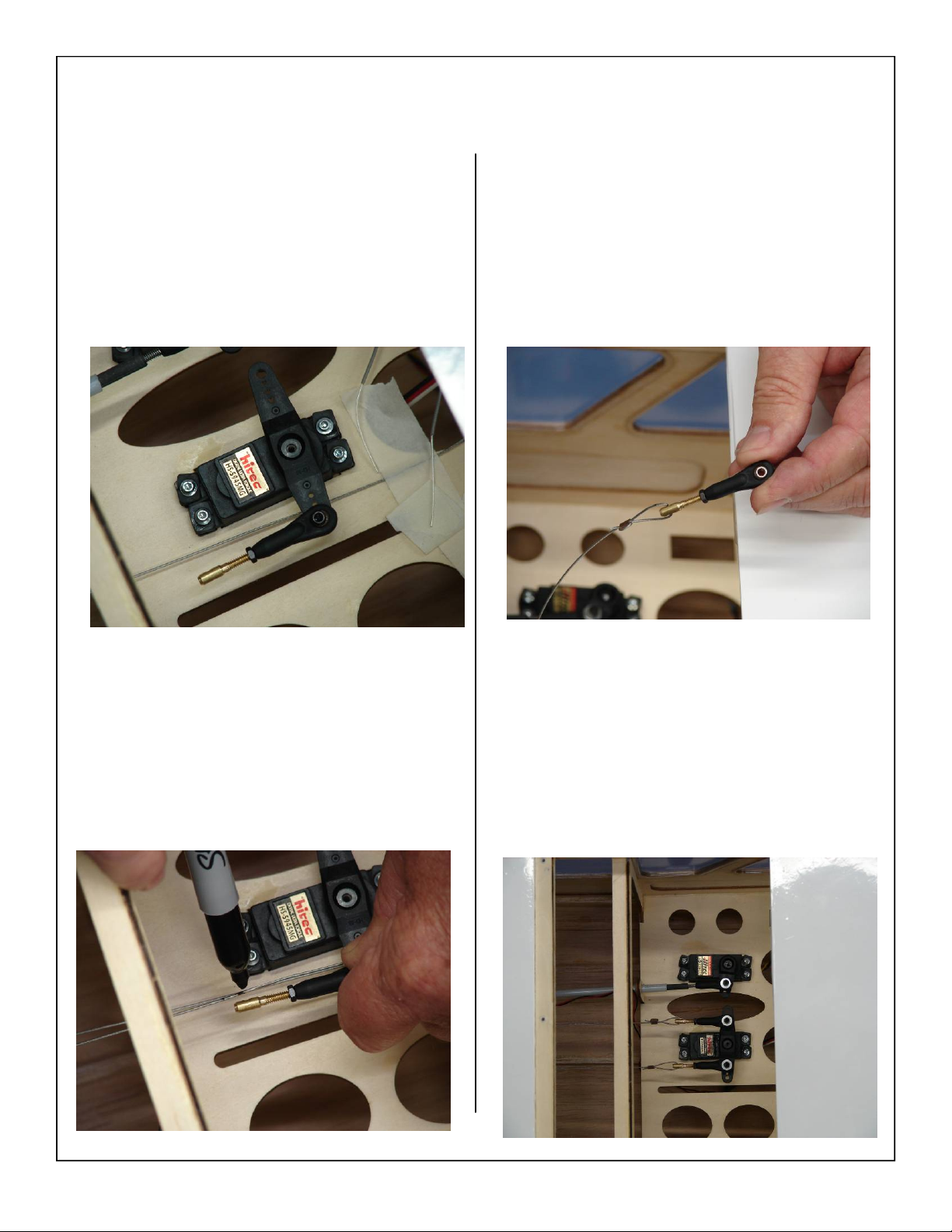
18. Attach the ball link to the servo arm using the 440 bolt, 4-40 lock nut and brass spacer as shown
below.
20. Mount threaded coupler to cable using the same
method used in previous steps.
19. Pull the pull pull cable tight and mark where
they will align with the hole in the threaded coupler as shown below.
21. Attach the ball link to the servo arm using the 440 bolt, 4-40 lock nut, washer, and brass spacer
as shown below.
38
Page 39
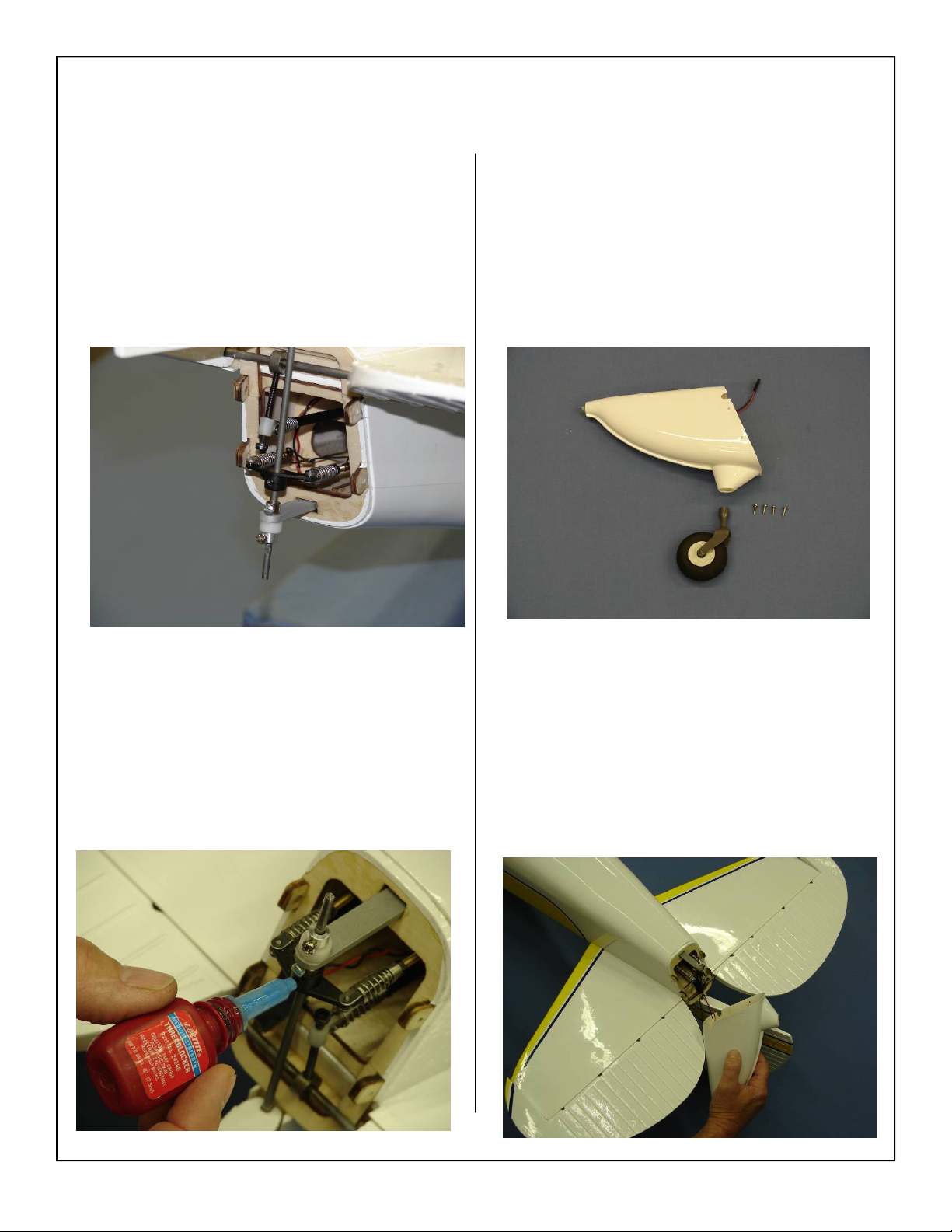
22. Ensure that the spring keepers are installed on
the clevises and are pushed as far forward as
possible. This will ensure the clevis will not slip
off during flight, zip ties or fuel line may also be
used.
24. Gather the tail cone, tail wheel assembly, and 4
wood screws for mounting of the tail cone as
shown below.
23. Remove the set screw holding the rudder control
horn in place and use blue loctite to ensure it
will not loosen in flight.
25. Install tail cone to the rear of the fuse using the 4
wood screws supplied in the kit. Remember to
connect the tail light extension at this time.
39
Page 40
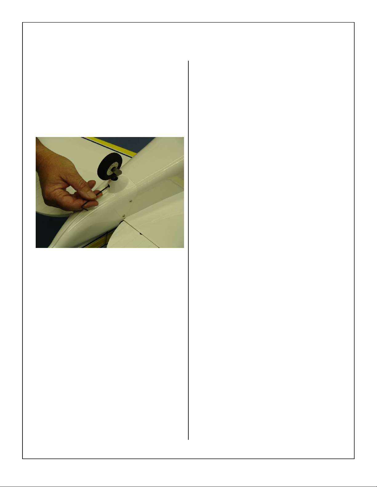
26. Install the tail wheel onto the tail wheel mounting shaft and tighten set screw as shown below.
Note: Use blue loctite to ensure the set screw does
not come loose due to vibration.
40
Page 41
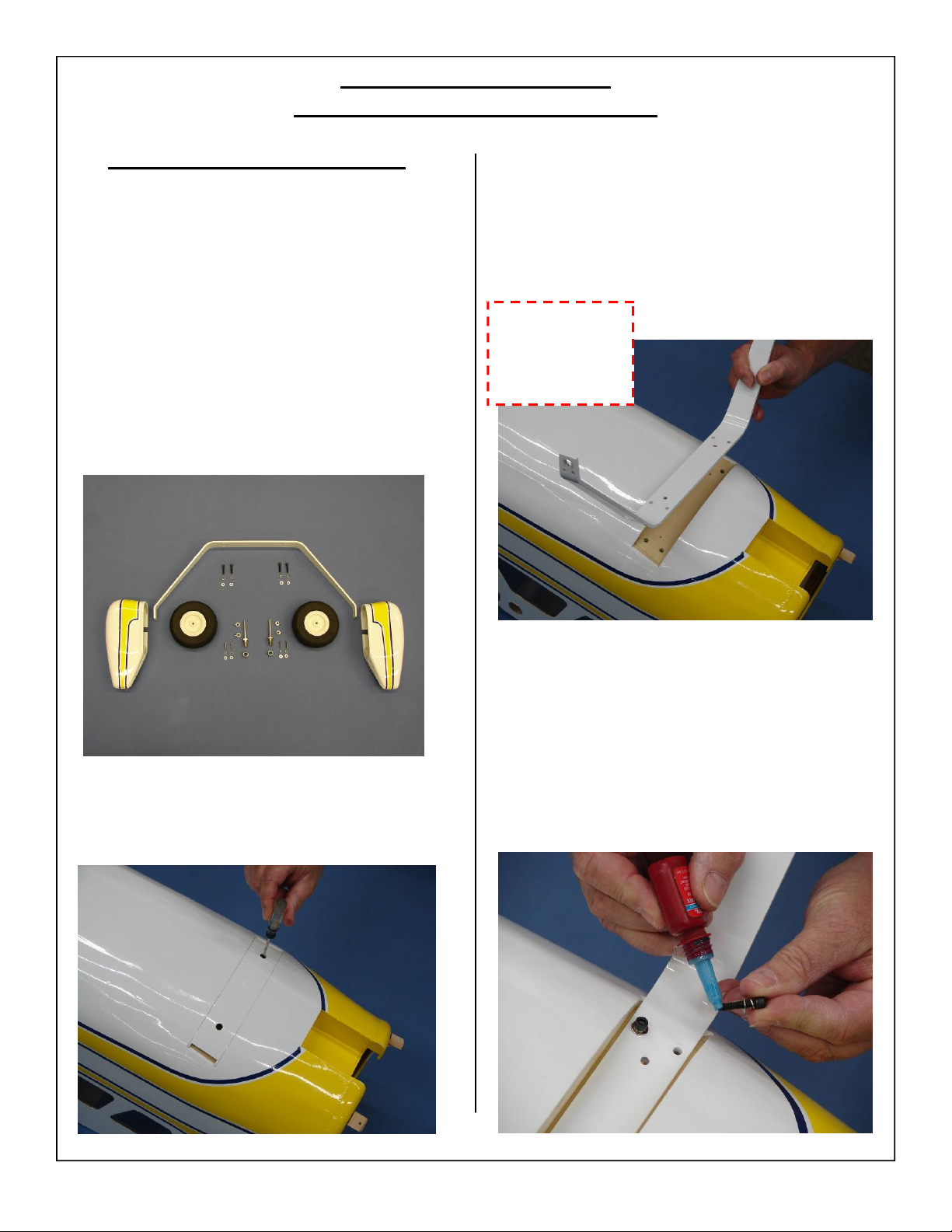
MAIN LANDING GEAR
AND WHEEL PANT AS SEMBLY
Main Landing Gear Installation
1. Gather the landing gear parts as shown below:
• (1) Landing Gear Strut
• (4) 8-32 mounting bolts
• (4) 4mm flat washers
• (4) 4mm lock washers
• (2) Wheel Pants
• (4) 4-40 mounting bolts
• (4) 3mm flat washer
• (4) 3mm lock washer
• (2) wheels
• (2) axles assemblies
• (4) wheel collars
3. Align mounting holes of main landing gear with
pre drilled mounting holes in fuselage mounting
plate.
Note: Mounting holes have been offset to ensure
proper installation of main gear.
Mounting holes
have been offset
to ensure correct
installation
2. Remove the Phillips head screws holding the
landing gear cover in place.
4. Assemble the landing gear bolts with lock
washer and flat washer. Use a drop of blue Loctite on landing gear bolts before attaching the
landing gear.
41
Page 42
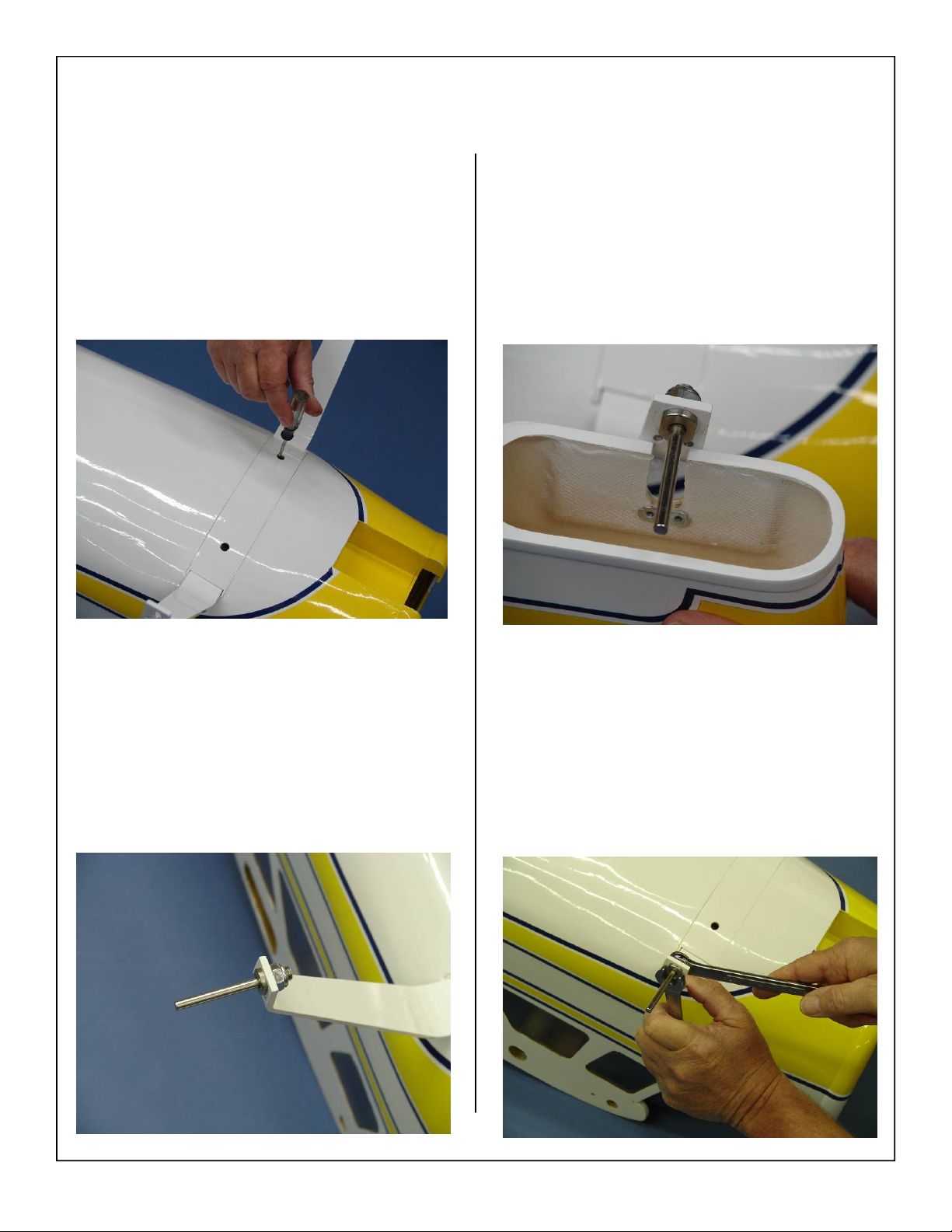
5. Reinstall the landing gear hatch cover.
7. Align the wheel pant slot over the axle bolt as
shown. Slide the wheel pant slot over the flat
sides of the axle bolt and align blind nuts in
wheel pants with mounting holes in landing
gear.
Note: Do not tighten securely yet.
6. Using lock nut install axle to gear.
Note: Do not tighten securely yet.
8. When holes are aligned tighten the lock nut
against the landing gear strut to secure axle.
42
Page 43
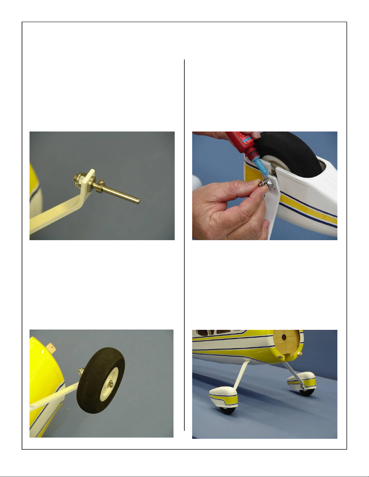
9. Install the inner wheel collar on the axle. Use a
drop of blue Loctite on the wheel collar set
screw and tighten the wheel collar in place.
11. Final installation of wheel pant with two mounting bolts. Use blue Loctite on the 4-40 mounting
bolts before final tightening.
Note: Make sure wheel turns freely without
binding or rubbing against the wheel pant.
Adjust wheel collars in or out until wheel turns
freely.
10. Install the wheel and outer wheel collar. Use
blue Loctite on the wheel collar set screw before
final tightening.
12. Repeat above steps for other wheel and wheel
pant.
13. Final landing gear installation shown below.
43
Page 44
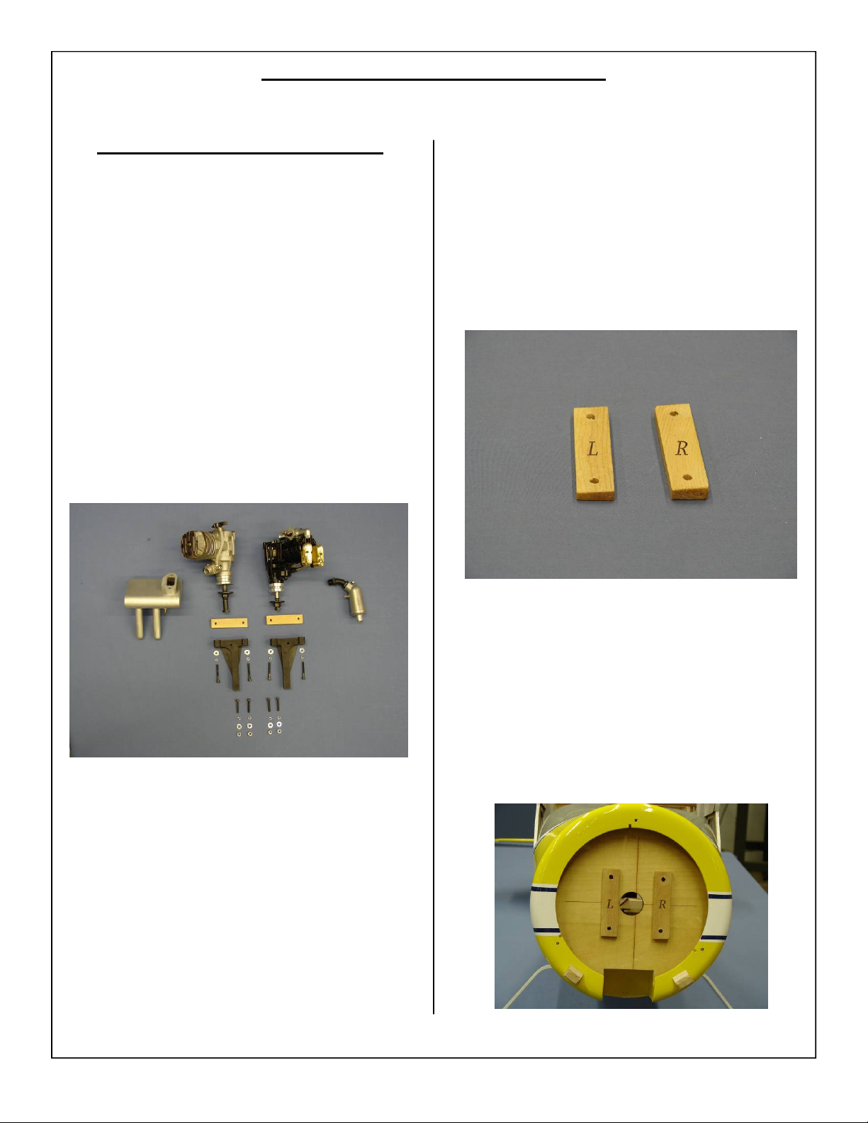
GLOW ENGINE INSTALLATION
4 Stroke Glow Engine Installation
1. The 1.80/ 30cc Cessna 195 will accept a wide
range of engine types. The Satio 1.80, OS 1.60
and DLE 30 was mounted The Satio 1.80 was
used for the test flights.
2. Satio 1.80 with stock muffler, OS 1.60 with Pitts
muffler and mounting hardware shown below.
Note:
Mounting distance from front of firewall to
front of engine prop hub for glow engines:
6 1/2”
3. Locate the engine mount standoffs for the vertical motor installation as shown below. There
will be a right and left side as shown below, this
will create the correct thrust angle for the engine.
4. The standoffs will need to be oriented as shown
below. It is very important that they are placed
on the correct side of the firewall to achieve the
proper thrust angle.
44
Page 45
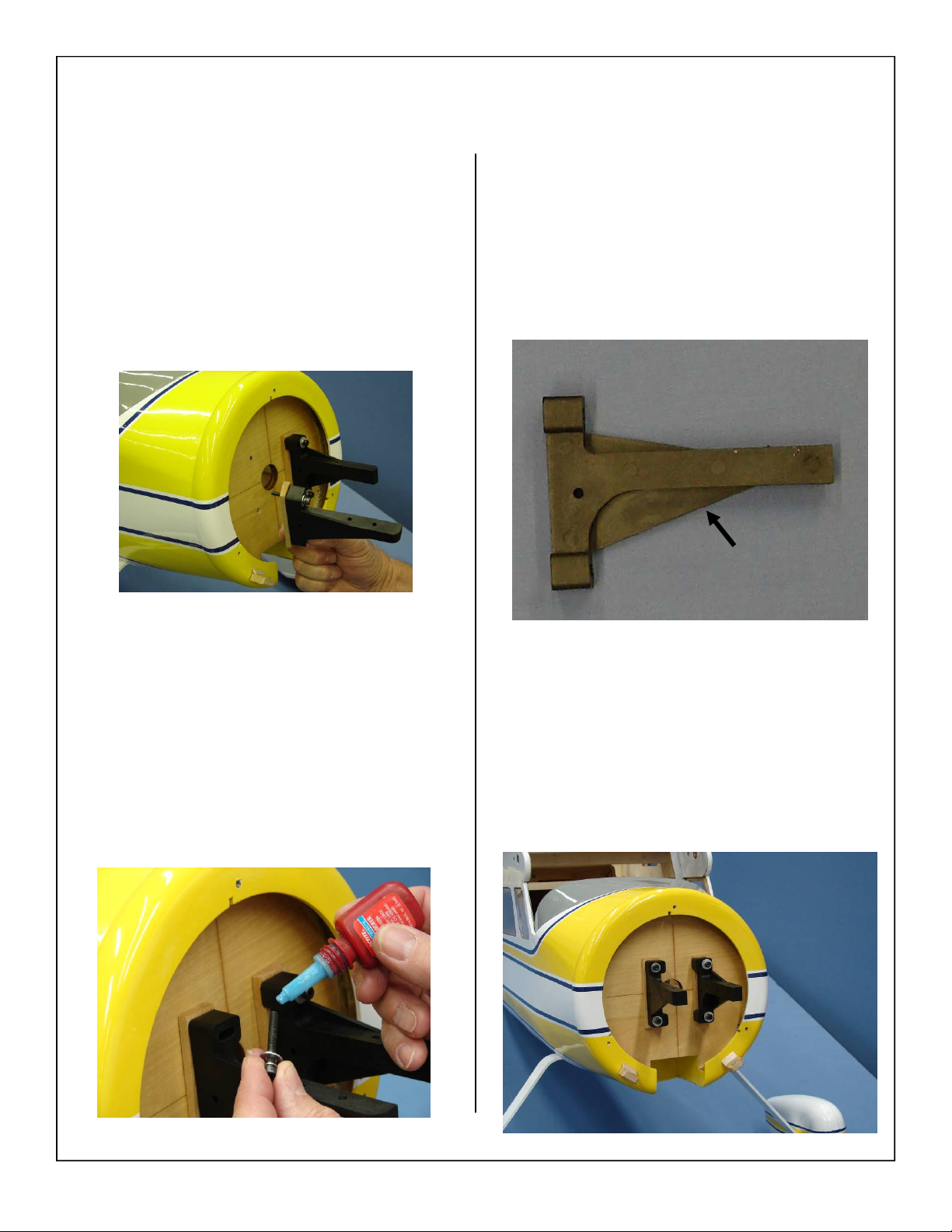
5. Install left and right side of the engine mounting
rails using the supplied 8-32 x 35mm bolts, flat
washers, and split lock washers. The blind nuts
have already been installed in the firewall.
7. Install the mount to the firewall using the diagram shown below. It is extremely important
that the mount be mounted with the larger reinforcing flange towards the engine.
Motor mounts
on this side
6. Use blue loctite on the mounting bolts to ensure
they do not loosen from vibration.
8. Install all four 8-32 x 35mm mounting bolts as
shown below.
45
Page 46
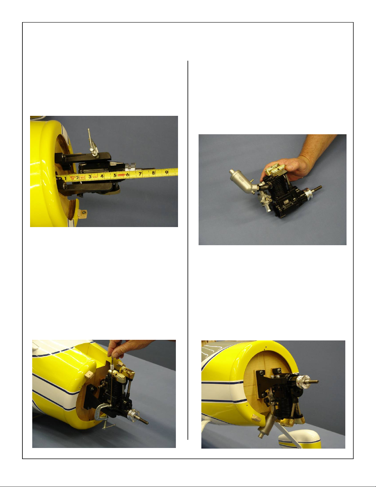
9. Set the engine in between the left and right
mounting rails. It may be necessary to clamp the
motor in place for the next few steps.
10. Adjust the motors position until the thrust washer
is 6 1/2” away from the firewall.
11. Mark the position of the engine mounting holes
on the engine mount. Mark the center of each
engine mounting hole
with a center marking tool or beveled pencil or
pen. Ensure the mark is in the center of the en-
gine mounting hole.
Note: We recommend the Great Planes
Dead Center Engine Mount Hole Locator
Part #GPMR8130
.
12. Attach the muffler to the engine as shown below. It may be necessary to slightly adjust the
angle of the muffler for the best fit.
13. Use 4 8-32 x 30mm bolts, 4 flat washers, and 4
8-32 lock nuts to install the engine to the mount.
46
Page 47
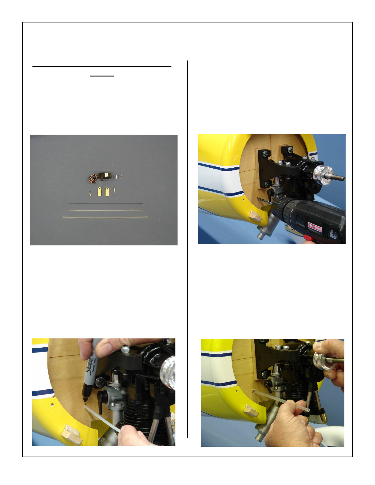
Throttle servo installation for 4 stroke
engine
1. Gather the throttle servo, (2) plywood pushrod
guides, (1) metal clevises with threaded insert,
(1) 4-40 rod, (1) nylon keeper(1) pushrod guide
tube, and (1) throttle pushrod.
3. Use a drill bit to drill the hole for the throttle
pushrod guide tube
2. Mark location of the throttle pushrod guide tube
onto the firewall.
Note: Insure throttle pushrod is lined up with
throttle arm of the carb.
4. Install the throttle pushrod guide tube into the
hole drilled in a previous step.
47
Page 48
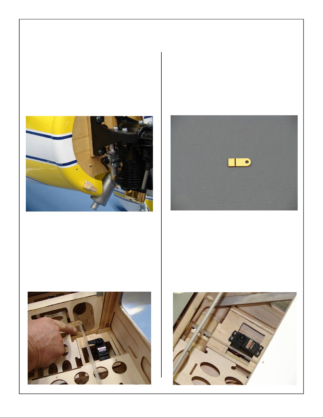
5. Push guide tube through the firewall.
7. Remove the unneeded portion of the plywood
pushrod guide as shown. If this is not done the
guide may interfere with the mounting of the
fuel tank.
6. Using plywood guide align pushrod guide tube
with servo arm. Mark plywood guide location.
8. Glue the plywood pushrod guide in place as
shown. Make sure the guide tube is aligned with
the servo arm as shown.
48
Page 49
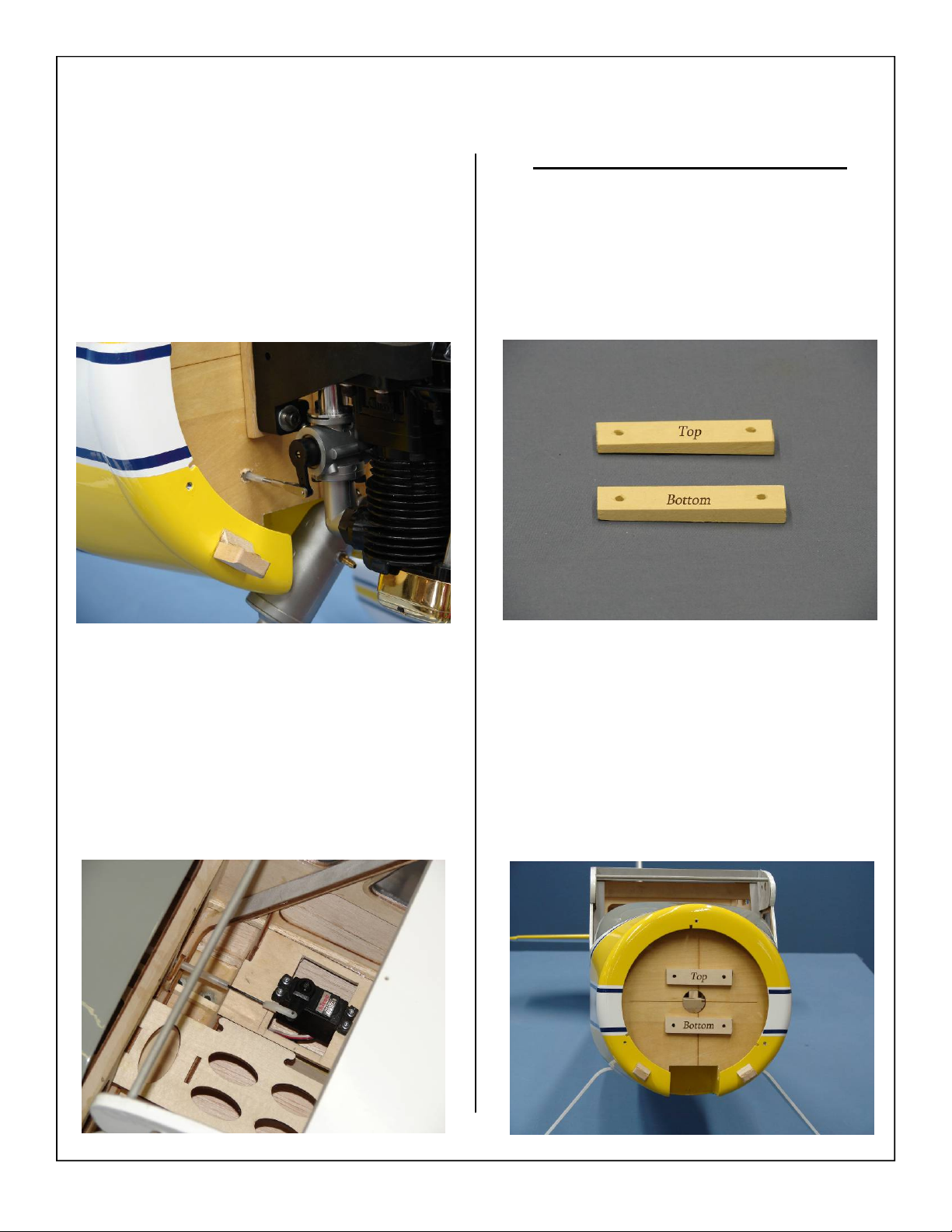
9. Slide the pushrod through the guide tube and install the threaded rod with the clevis. Attach the
clevis to the carburetor.
2 Stroke Glow Engine Installation
1. Locate the engine mount standoffs for the horizontal motor installation as shown below. There
will be a top and bottom spacer as shown below,
this will create the correct thrust angle for the
engine.
10. Install the remaining threaded rod and nylon
keeper on the other side of the throttle pushrod.
Attach the clevis to the throttle servo.
2. The standoffs need to be oriented as shown below. It is very important that they are placed in
the correct location of the firewall to achieve the
proper thrust angle.
49
Page 50
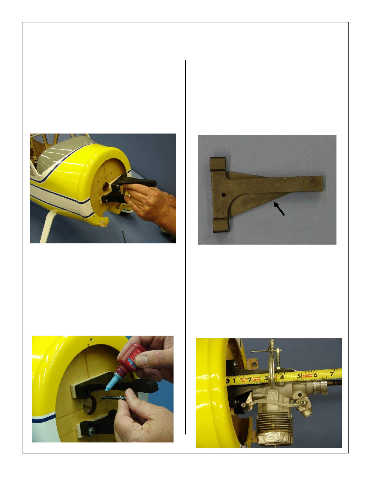
3. Install top and bottom side of the engine mounting rails using the supplied 8-32 x 35mm bolts,
flat washers, and split lock washers. The blind
nuts have already been installed in the firewall.
5. Install the mount to the firewall using the diagram shown below. It is extremely important
that the mount be mounted with the larger reinforcing flange towards the engine.
Motor mounts
on this side
4. Use blue loctite on the mounting bolts to ensure
they do not loosen from vibration.
6. Set the engine in between the top and bottom
mounting rails. It may be necessary to clamp the
motor in place for the next few steps.
7. Adjust the motors position until the thrust
washer is 6 1/2” away from the firewall.
50
Page 51
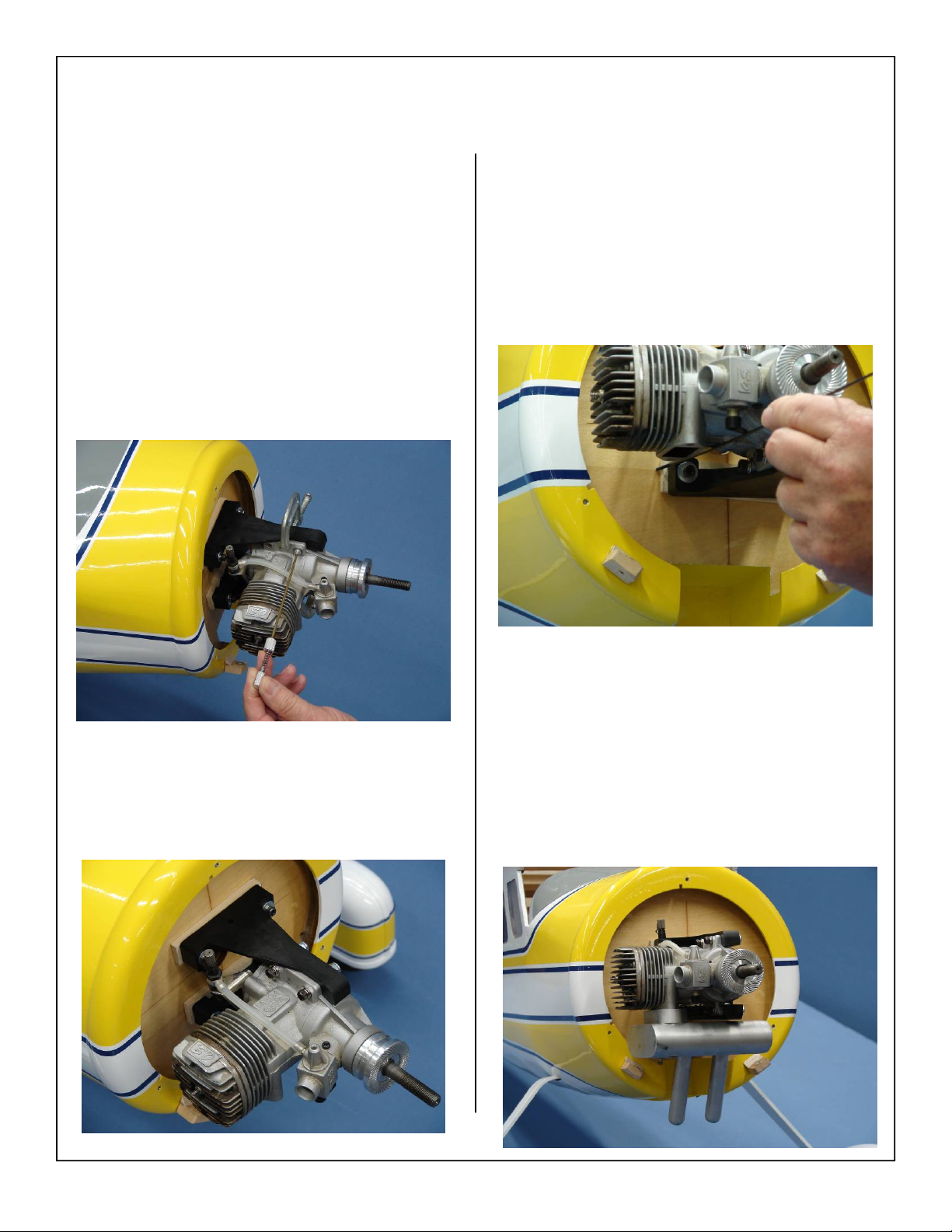
8. Mark the position of the engine mounting holes
on the engine mount. Mark the center of each
engine mounting hole
with a center marking tool or beveled pencil or
pen. Ensure the mark is in the center of the en-
gine mounting hole.
Note: We recommend the Great Planes
Dead Center Engine Mount Hole Locator
Part #GPMR8130
.
10. Mark location of the throttle pushrod guide tube
onto the firewall.
Note: Insure throttle pushrod is lined up with
throttle arm of the carb.
Note: Follow steps outlined for 4 stroke throt-
tle pushrod assembly
9. Use 4 8-32 bolts, 4 flat washers, and 4 8-32 lock
nuts to install the engine to the mount.
11. Install muffler onto the motor as shown. Blue
loctite is recommended to prevent the bolts from
loosening in flight.
51
Page 52
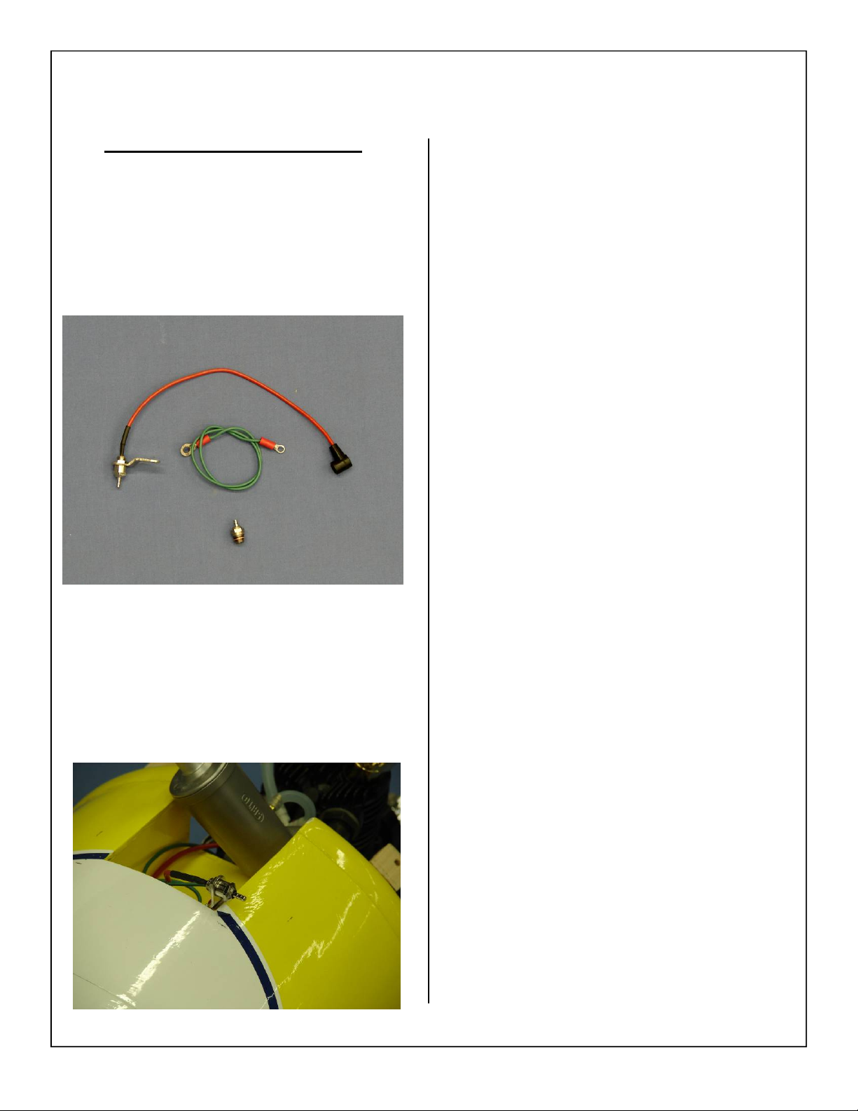
Remote Glow Plug Installation
1. Gather the remote glow plug assembly as shown
below.
Note: Remote glow plug is an optional
accessory and is not included with the kit.
2. Install the remote glow plug assembly as shown
below. Refer to remote glow plug manufacturers
instructions for specific mounting techniques.
52
Page 53
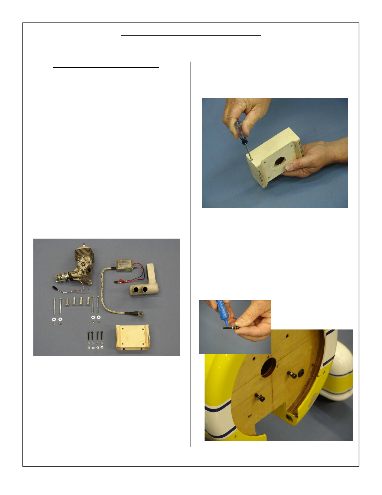
GAS ENGINE INSTALLATION
30cc Gas Engine Installation
1. The 1.80/ 30cc Cessna 195 will accept a wide
range of engine types. The Satio 1.80, OS 1.60
and DLE 30 was mounted The Satio 1.80 was
used for the test flights.
2. DLE 30, Ignition, Muffler, mounting bolts with
hardware, 1 1/16” standoffs, Motor box, Motor
box mounting hardware shown below.
Note:
Mounting distance from front of firewall to
front of engine prop hub for gas engines:
6 3/4”
Note: optional wrap around muffler (not shown)
available from Aeroworks
3. Locate the engine mount and remove the 3 wood
screws holding the top hatch in place.
4. Install the bottom 8-32 x 20mm bolts lock washers and flat washers for the engine mount as
shown. Use blue loctite to ensure the bolts will
not loosen from vibration.
Note: Use only 8-32 x 20mm bolts to keep from
puncturing fuel tank.
53
Page 54
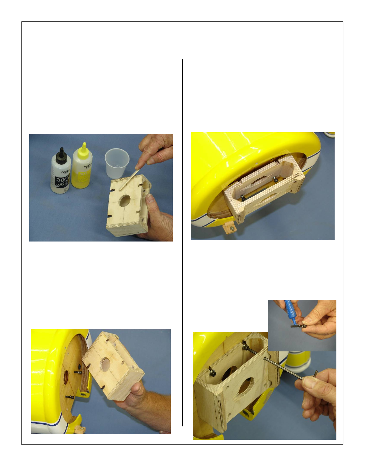
5. Mix 30 minute epoxy in mixing cup and use a
stick to apply the epoxy to the back side of the
engine mount as shown.
.
7. Tighten the engine mounting bolts as shown be-
low. Wipe away any epoxy with alcohol wetted
wipes
6. Slide engine mount over the 8-32 x 20mm bolts
installed in a previous step as shown.
8. Install the remaining engine mount bolts with
lock washers and standard washers as shown.
Use blue loctite to ensure the bolts will not
loosen from vibration.
54
Page 55
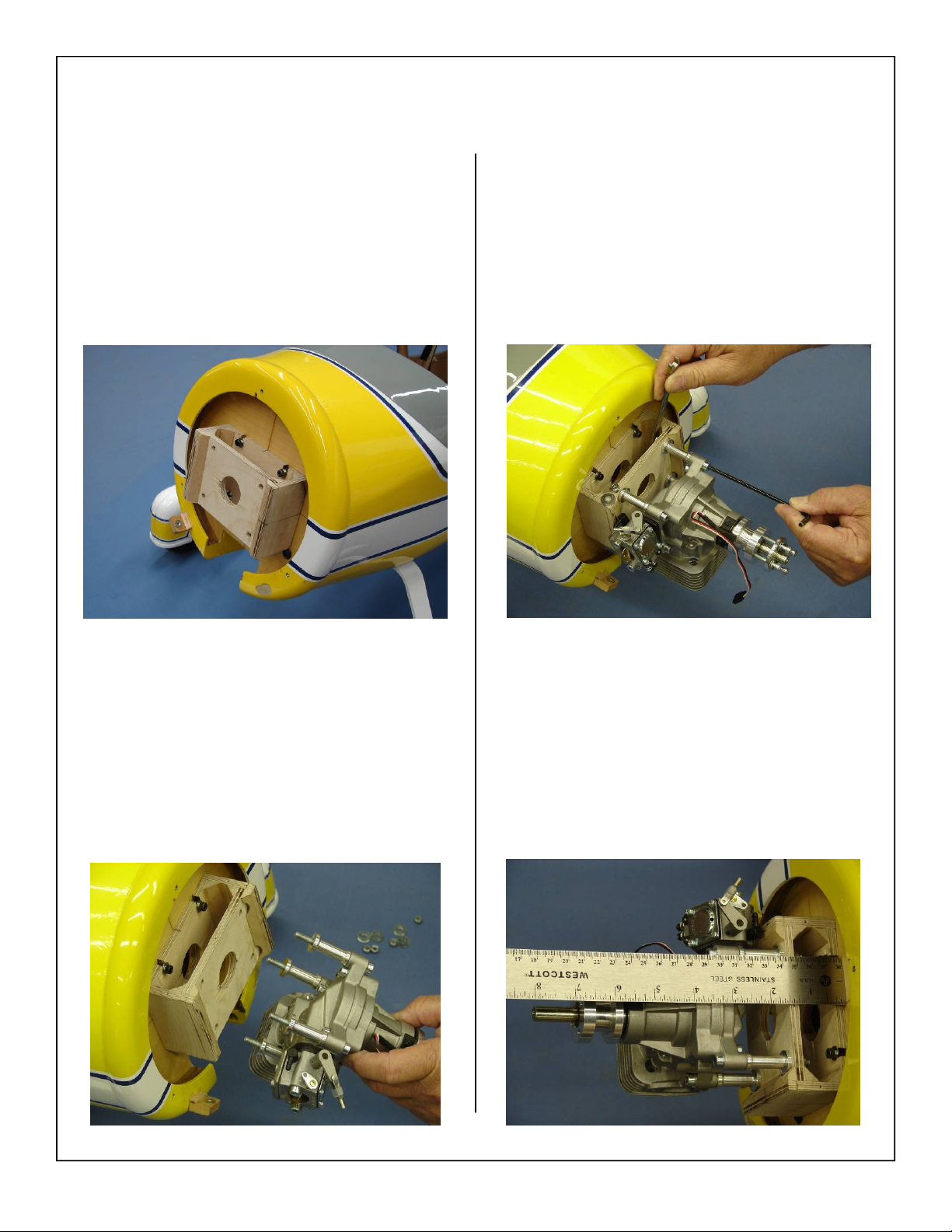
9. Finished engine mount installation shown below.
11. Install washers and lock nuts on the back side of
the engine mount and tighten engine mounting
bolts as shown.
Note: Do not over tighten engine mounting bolts,
this can cause the wood to compress and will
weaken the engine mounting box.
10. Locate the engine standoffs, mounting bolts,
lock nuts, and washers. Slide the bolts through
the engine and install standoffs as shown. Slide
the engine mounting bolts through the pre
drilled holes in the engine mount.
12. Distance from front of firewall to front of
engine prop hub is 6 3/4”.
55
Page 56
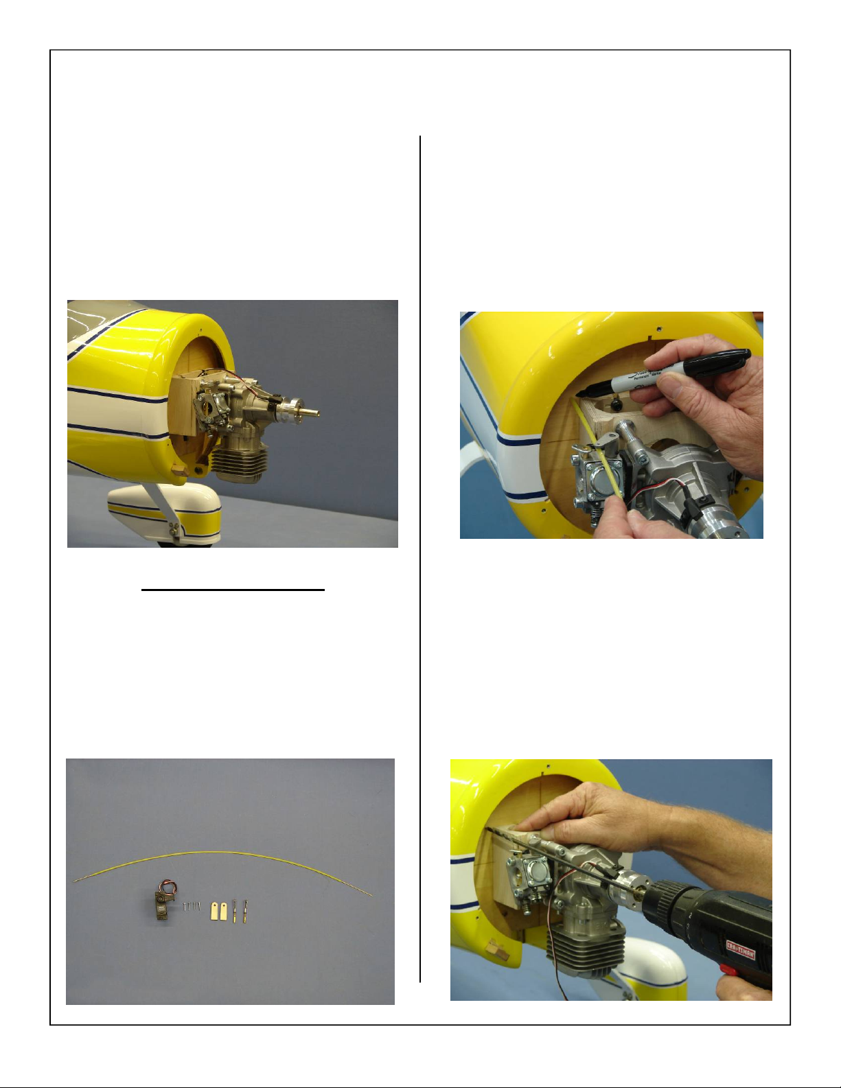
13. Final DLE 30 installation shown below.
2. Mark location of the throttle pushrod guide tube
onto the firewall.
Note: Insure throttle pushrod is lined up with
throttle arm of the carb.
Throttle servo installation
1. Gather the throttle servo, 1” servo arm, (4) servo
mounting screws, plywood pushrod guides, and
Sullivan pushrod set part# S503 as shown below.
Note: throttle hardware for gas engine not supplied.
3. Use a drill bit to drill the holes for the throttle
pushrod guide tube
56
Page 57
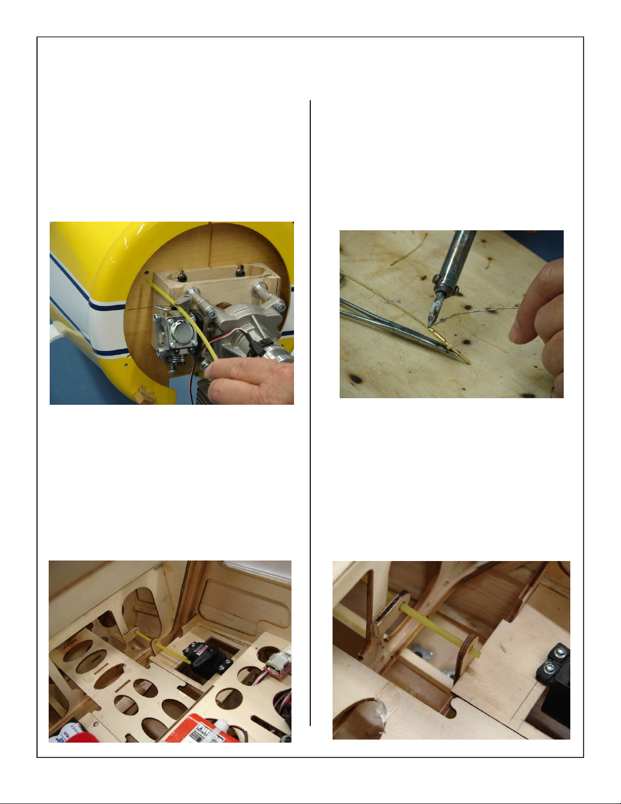
4. Slide the pushrod through the hole drilled in the
previous step as shown. Ensure that the pushrod
goes all the way to the throttle servo mount.
6. Solder the brass coupler to the pushrod as shown
below.
5. Install throttle servo with the output shaft facing
the tail as shown. Follow steps outlined in the
glow engine installation on page 48 for plywood
pushrod guide installation.
7. Glue the pushrod guide tube to the plywood
guides as shown. Trim the guide tube flush with
the rear guide.
57
Page 58
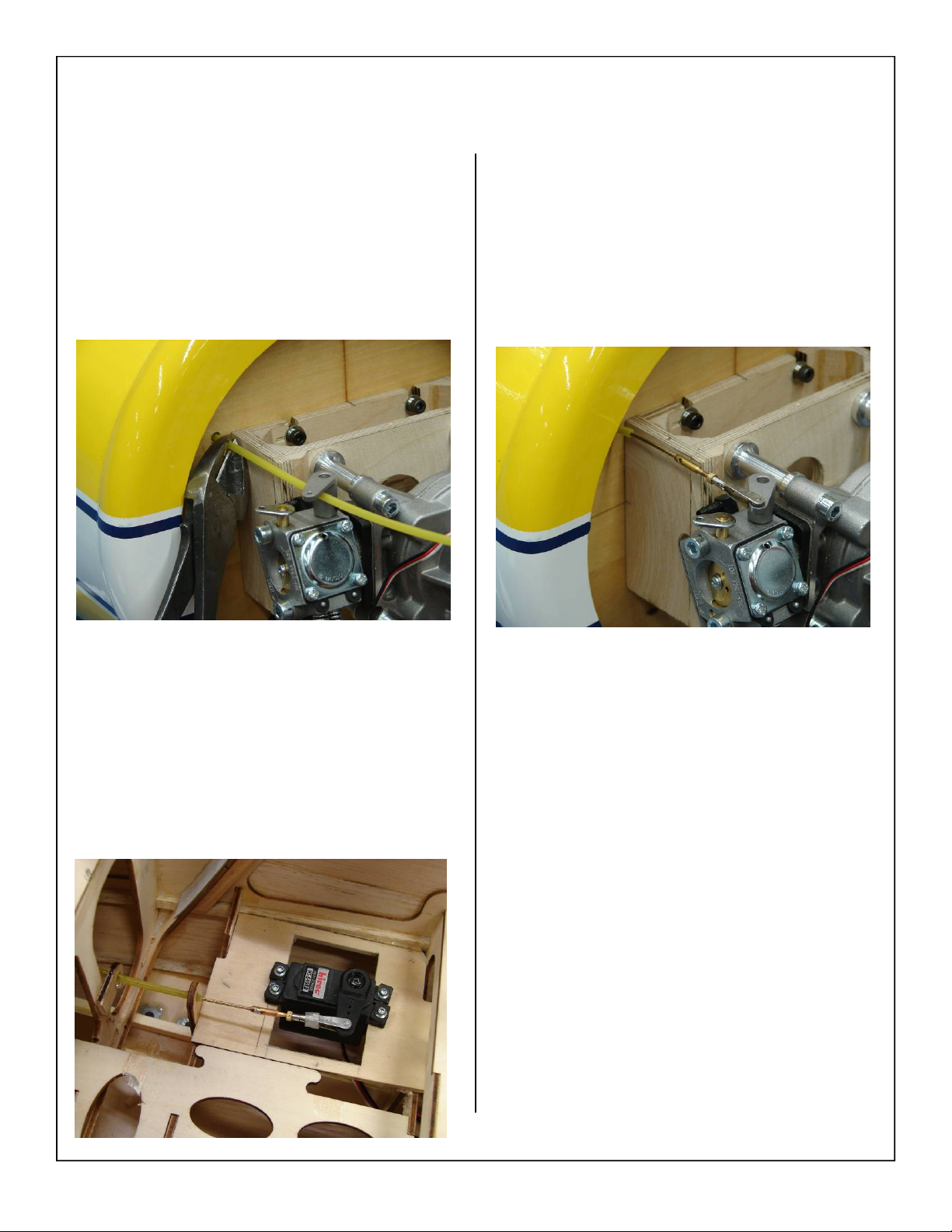
8. Trim the pushrod guide tube flush with the firewall as shown below.
10. Install the clevis on the throttle arm of the carburetor and solder in place.
11. Throttle installation is now complete.
9. Slide the pushrod through the guide tube from
inside the fuse out towards the engine. Attach
the clevis to the servo arm as shown.
Note: Use a piece of fuel line over the clevis to pre
vent it from coming loose in flight.
58
Page 59
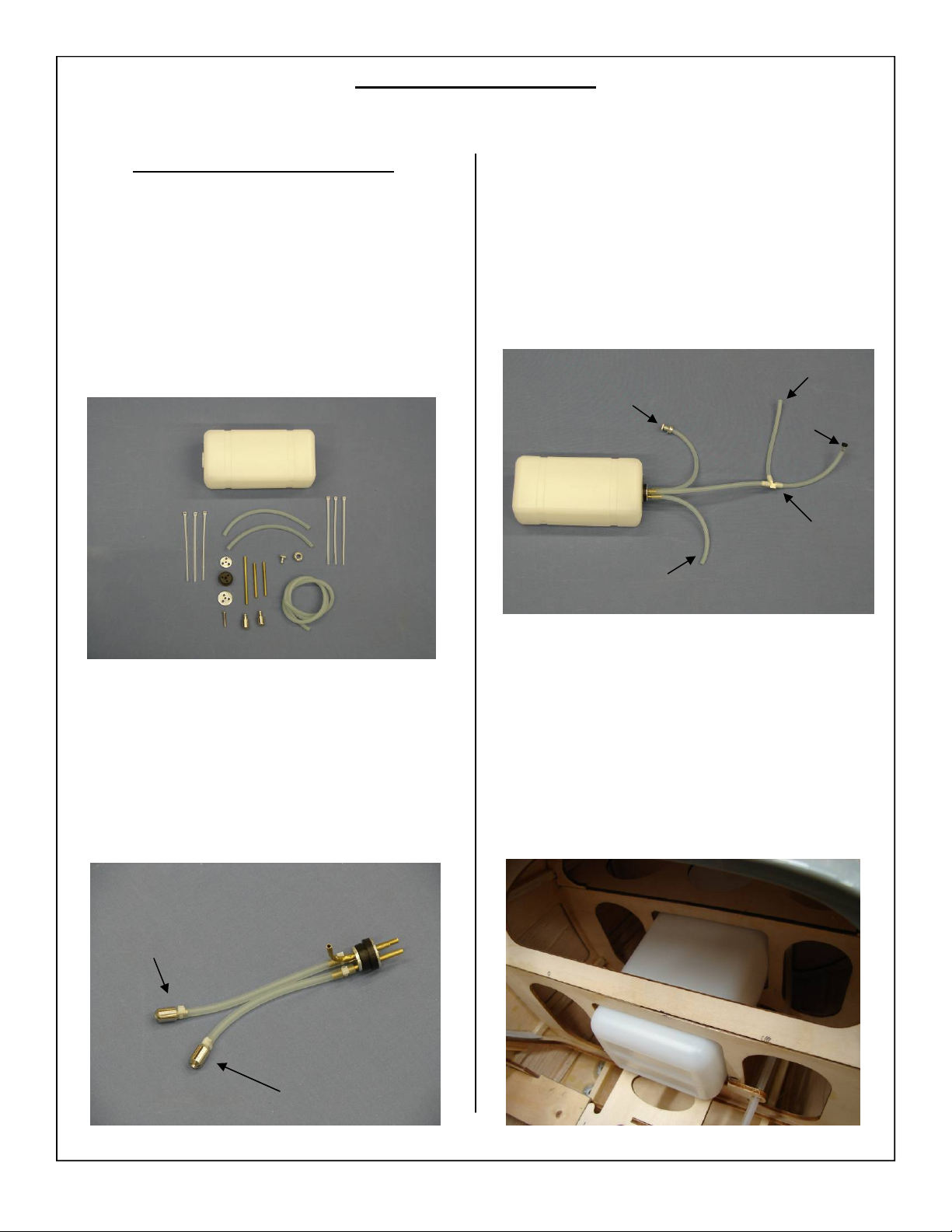
Fuel Tank Installation
Glow Fuel Tank Installation
1. Gather the fuel tank parts as shown below. Fuel
tank, hardware, and fuel tubing.
Note: Fuel tank stopper can be used for both gas or
glow fuel.
3. Assemble the fuel tank as shown below.
Note: Fuel “T” not supplied
Muffler Pressure
Fuel Dot
Overflow
2. Assemble the stopper as shown below. Use
Zip ties to secure the pick up line to the tubing
as well as to the clunk.
Fill
Fuel “T”
Fuel Line
4. Slide the fuel tank into the precut slots inside the
fuse as shown.
Carb
59
Page 60
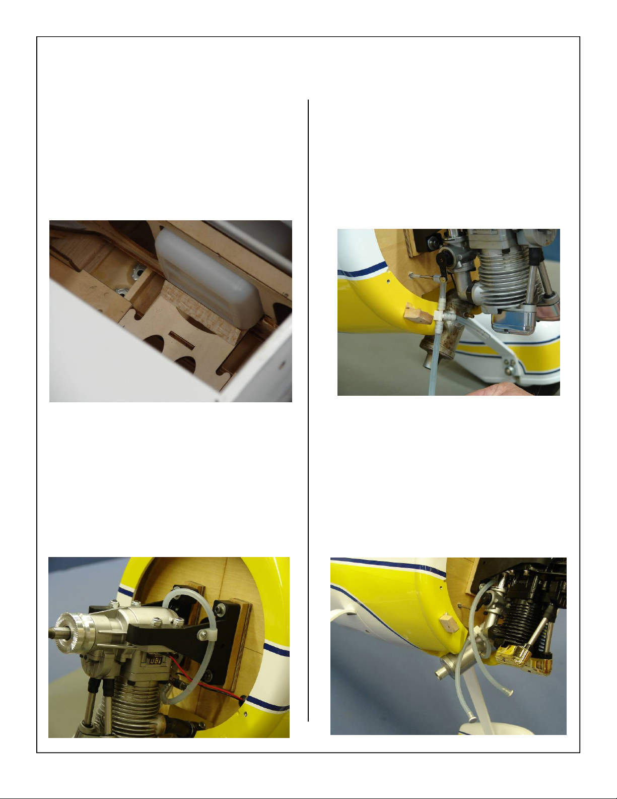
5. Locate the supplied tristock and glue in place
behind the fuel tank as shown. This will keep the
fuel tank secure during flight.
7. Attach the pressure line to the muffler.
6. Attach the fuel line to the carburetor inlet as
shown below.
8. Use two fuel dots to plug both the overflow and
the fill line as shown below.
60
Page 61
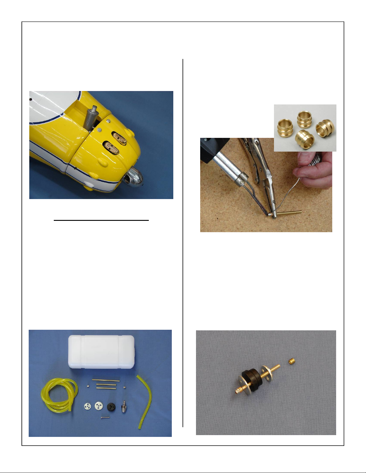
9. Install the two fuel dots in the lower portion of
the cowl as shown.
Gas Fuel Tank Installation
1. Gather the fuel tank parts as shown below.
• Fuel tank
• Hardware
• Brass barbs
• Fuel tubing
Note: Fuel tank stopper can be used for both gas or
glow fuel.
Note: Tygon fuel line is not supplied but is available
through Aeroworks
2. Locate the (2) supplied brass fuel barbs. Solder a
brass fuel barb to the fuel line pick up tube. This
will keep the weight of the fuel clunk from pulling the fuel line off the brass tube.
Note: No brass barbs are required for the air vent
lines.
3. Assemble the fuel pick up line, rubber stopper
and metal end caps. As shown below.
61
Page 62
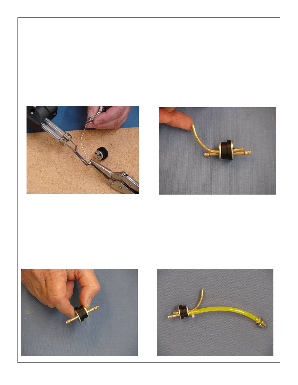
4. Solder a brass fuel barb to the other end of the
fuel pick up line.
6. Install air vent tube into rubber stopper and bend
upward.
Note: No brass barbs are required for the air vent
tube.
5. Final assembly of rubber fuel stopper with fuel
pick up tube shown below.
7. Install the fuel tubing and clunk. Secure the fuel
tubing with nylon ties to the pick-up tube and
clunk.
62
Page 63
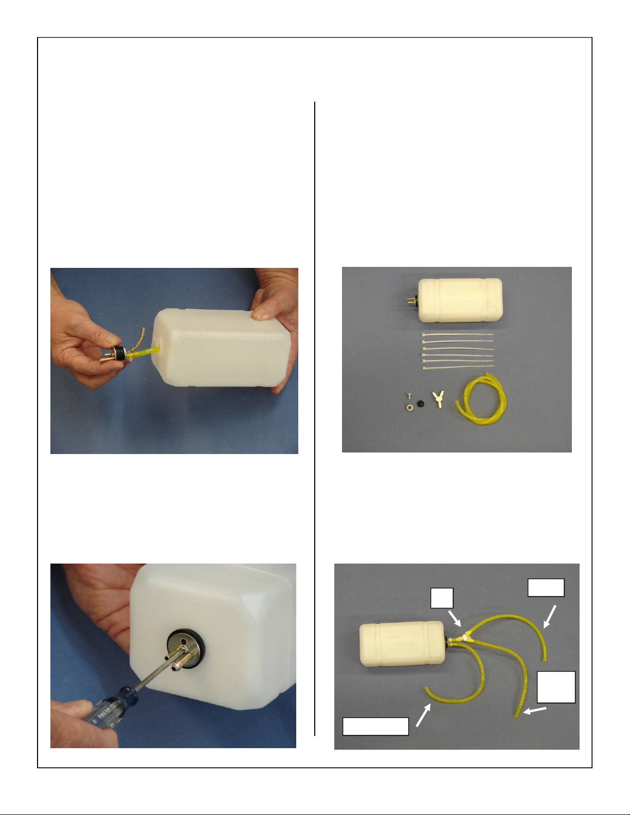
8. Insert the rubber stopper assembly into the tank
with the vent tube at the top of the tank.
1. Gather the fuel tank parts as shown below. Fuel
tank, fuel tubing,, fuel “T”, fuel filler dot, and
nylon ties.
Note: The fuel “T”, is not supplied, but is available
through Aeroworks.
9. Secure the rubber stopper with set screw. Take
care not to strip threads by over tightening set
screw.
2. Install the fuel filter, fuel pick up and fuel filler
lines to the fuel tank.
Carb
T
Fill
Line
Overflow
63
Page 64
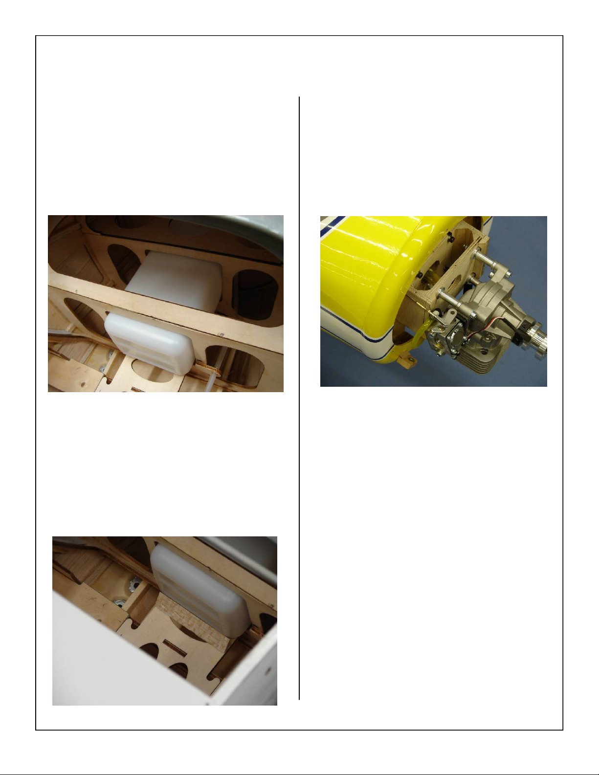
3. Slide the fuel tank into the precut slots inside the
fuse as shown.
5. Secure fuel pick up line to engine carburetor
with small nylon tie.
4. Locate the supplied tristock and glue in place
behind the fuel tank as shown. This will keep the
fuel tank secure during flight.
64
Page 65
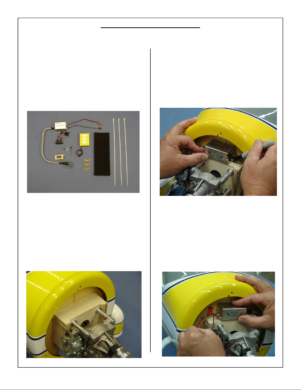
IGNITION INSTALLATION
1. Gather the ignition module, battery, switch,
switch mount, external switch pushrod assembly
(not supplied) Dubro Part # 203. and installation
parts as shown below.
3. Mark location for zip tie to pass through the
hatch as shown.
2. Place engine mount top hatch back on top of
engine mount.
4. Mark location for ignition power lead to pass
through the firewall as shown below.
65
Page 66
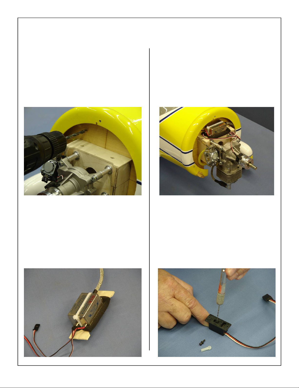
5. Drill the top hatch and ignition power lead holes
marked in the previous steps as shown below.
7. Secure ignition wire with nylon ties as necessary. Finished ignition installation shown
below.
6. Mount the engine ignition module using nylon
tie and foam rubber as shown.
8. If using the external switch pushrod assembly
drill a small hole in the switch as shown below.
66
Page 67
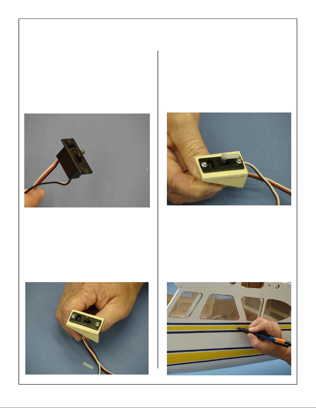
9. Install the ball joint onto the switch as shown.
11. Install ball link coupler onto the ball joint as
shown.
10. Install the switch into the switch mount as
shown.
12. Mark the location for the switch pushrod to pass
through the fuse. The final position is left to the
builder.
67
Page 68
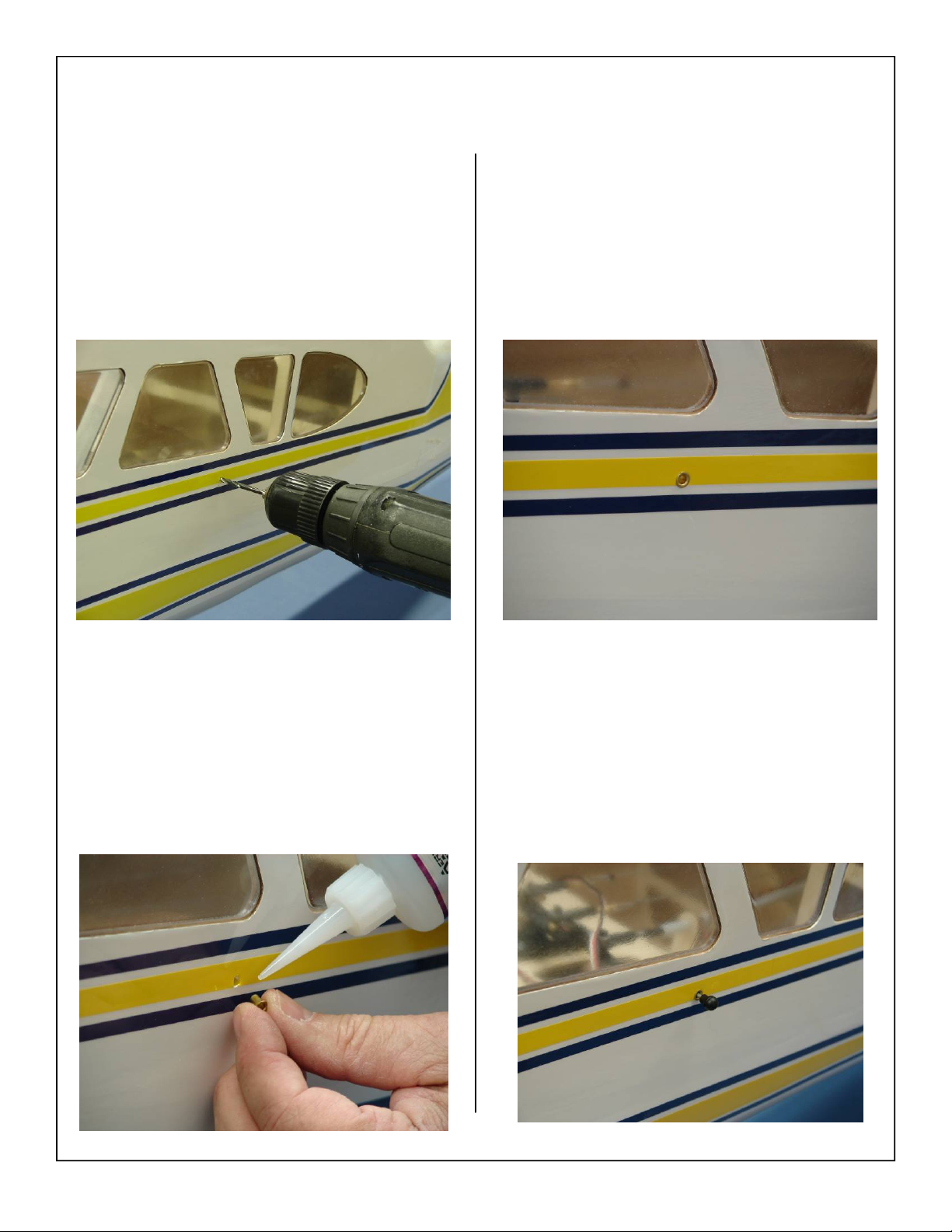
13. Drill through the fuse as shown below.
15. Finished eyelet installation shown below. The
flanged portion of the eyelet should be towards
the outside of the fuse.
14. Use thick CA to glue a brass servo eyelet into
the hole drilled in the previous step. This will
prevent the wood from breaking over time.
16. Install the switch pushrod with mounting ball as
shown below.
68
Page 69
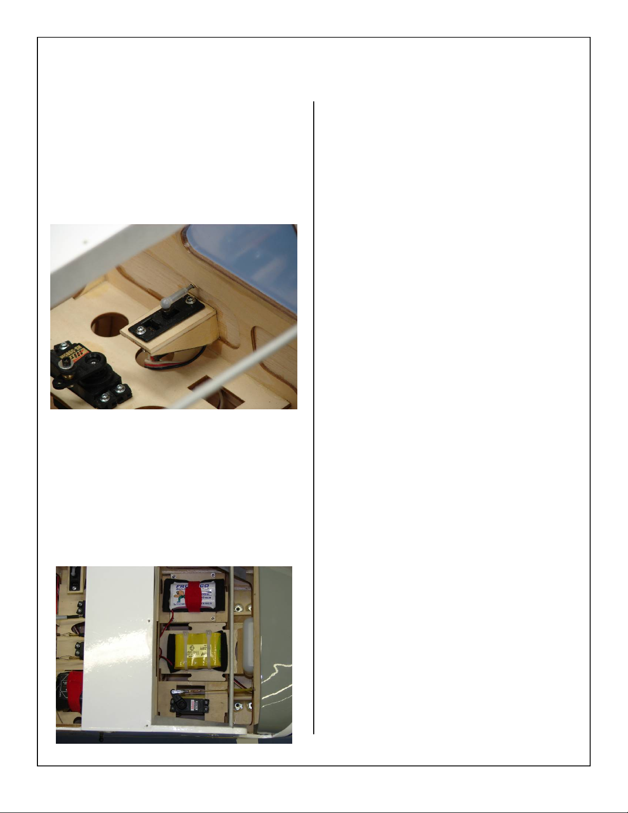
17. Use thick CA to glue the switch mounting box in
place as shown.
18. Mount the ignition battery using foam pad and
zip ties as shown below. Ignition installation is
now complete.
69
Page 70
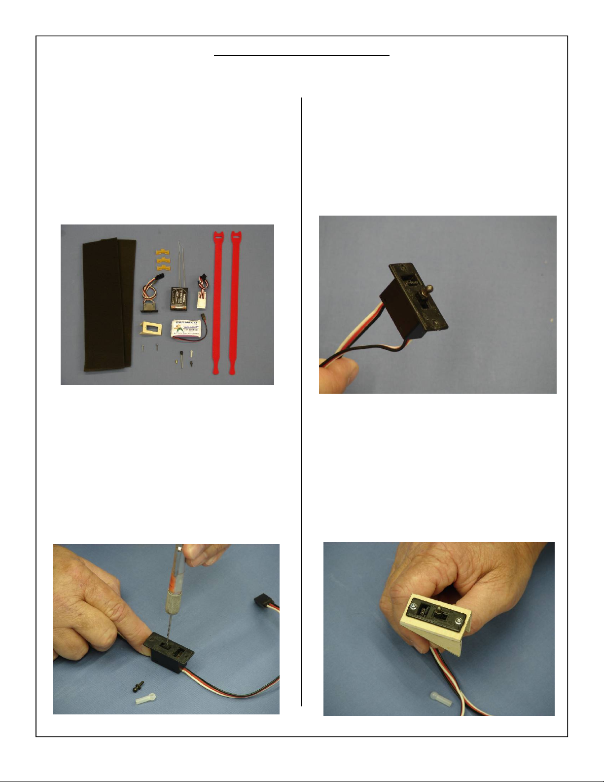
RADIO INSTALLATION
1. Gather the radio components as shown below.
Battery, Switch, Regulator if used, receiver,
switch mount, foam rubber and Velcro one wrap
straps.
3. Install the ball joint onto the switch as shown.
2. Mount radio switch in accordance with the
switch manufacturers instructions and hardware.
Note: Ensure switch does not interfere with wings
or cowl installation.
4. Install the switch into the switch mount as
shown.
70
Page 71
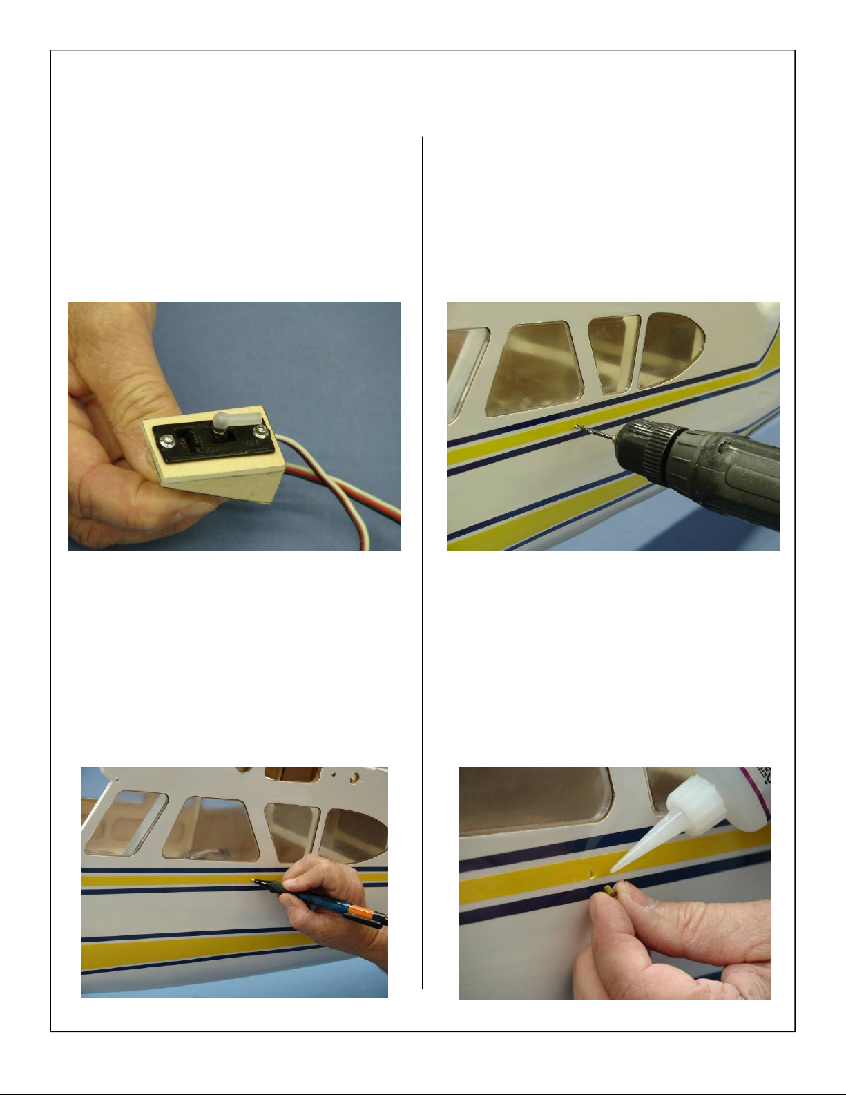
5. Install ball link coupler onto the ball joint as
shown.
7. Drill through the fuse as shown below.
6. Mark the location for the switch pushrod to pass
through the fuse. The final position is left to the
builder.
8. Use thick CA to glue a brass servo eyelet into
the hole drilled in the previous step. This will
prevent the wood from breaking over time.
71
Page 72
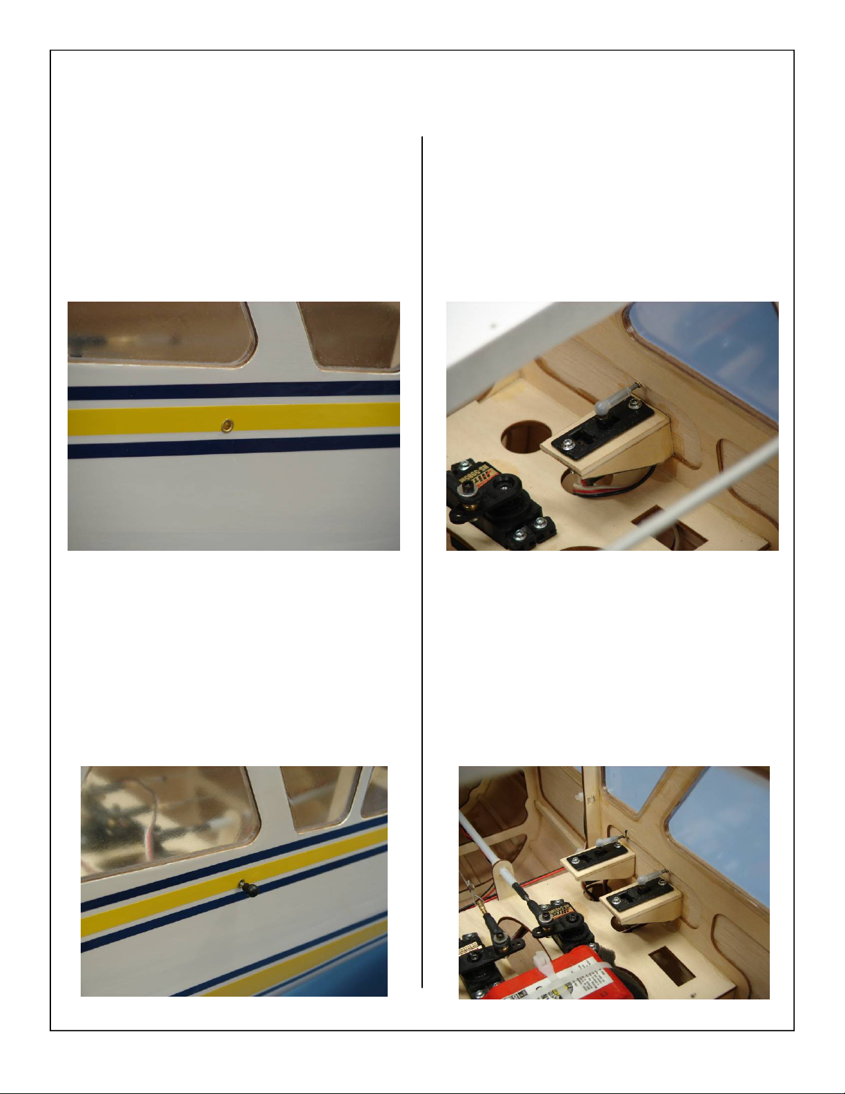
9. Finished eyelet installation shown below. The
flanged portion of the eyelet should be towards
the outside of the fuse.
11. Use thick CA to glue the switch mounting box in
place as shown.
10. Install the switch pushrod with mounting ball as
shown below.
12. If using the external lighting switch install it in
the same manner as described in the previous
steps for the receiver switch.
72
Page 73
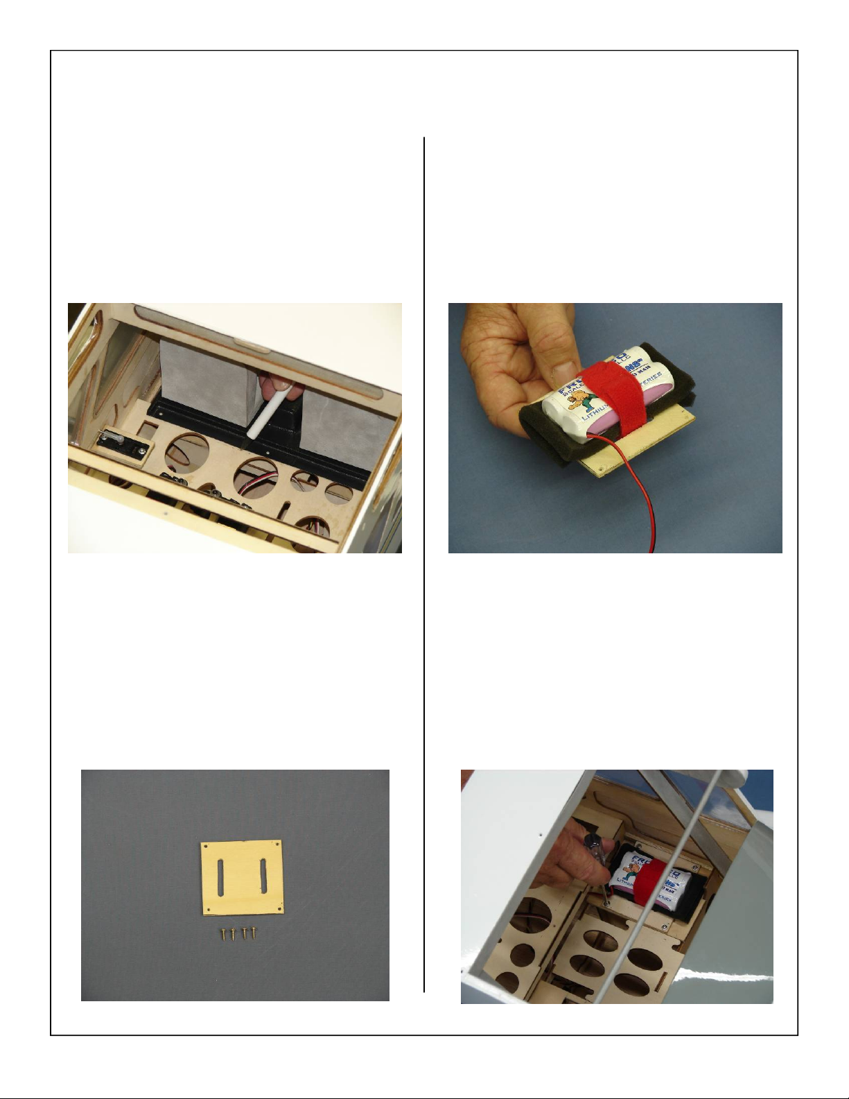
13. Temporarily place the cockpit back inside the
fuse and mark the location of the rear cockpit
floor onto the fuse floor as shown. This will allow the builder to locate as much of the electronics under the cockpit for a better scale look.
15. Install battery to battery tray using foam padding
and Velcro one wrap strap.
14. Gather the battery mounting tray and (4) wood
screws as shown below.
16. Screw the battery mounting tray to the fuse floor
as shown.
73
Page 74
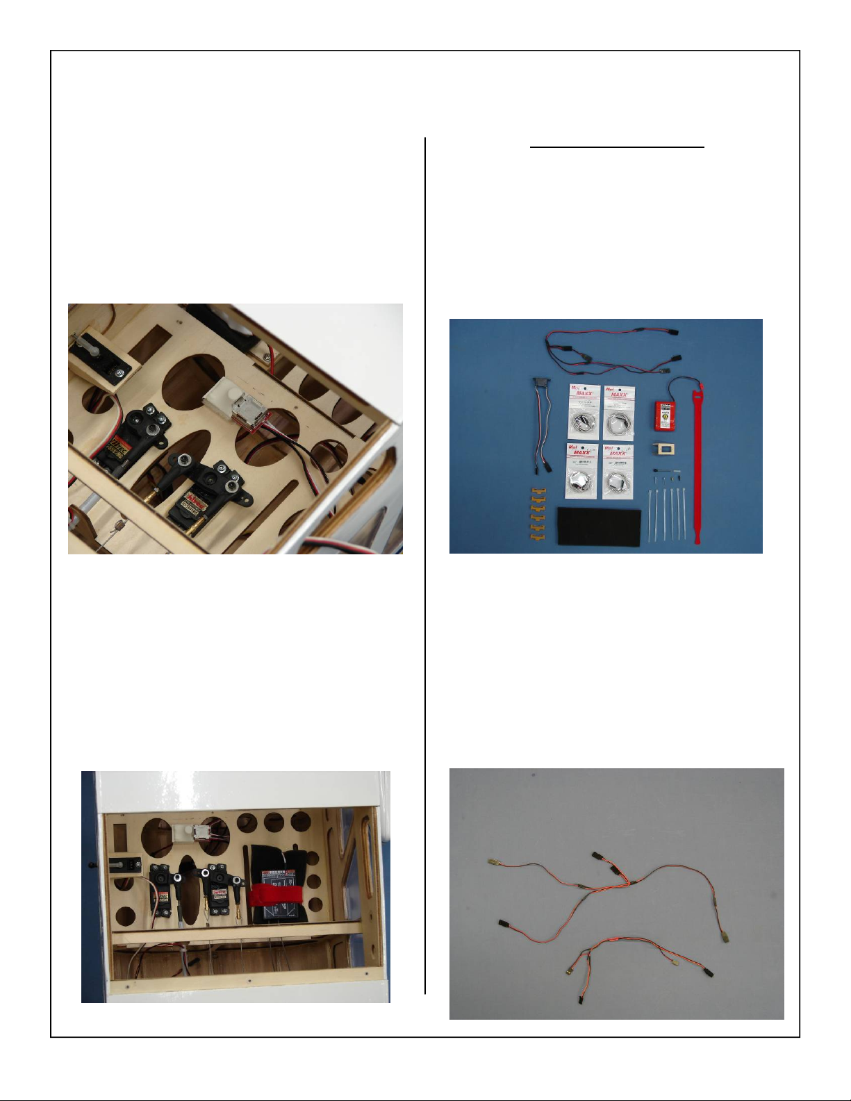
17. If a regulator is used install it at this time. Refer
to the regulator manufacturers instructions for
specific regulator mounting.
Lighting Kit Installation
1. Gather the following items for the optional lighting system. Wiring harness (supplied), switch,
4.8V battery, (2) 18” extensions, (2) 24” extensions, switch mount, Velcro strap, zip ties, foam
padding, (6) Aeroworks Safety Clips as shown
below.
18. Install the receiver using foam pad and Velcro
one wrap strap. Refer to receiver manufacturers
instructions for specific antenna orientation.
2. Both the included (top) as well as the optional
remote (bottom) wiring harnesses are shown
below. The remote harness will enable the pilot
to turn the lights on and off via the transmitter.
This harness is available from Aeroworks separately.
74
Page 75
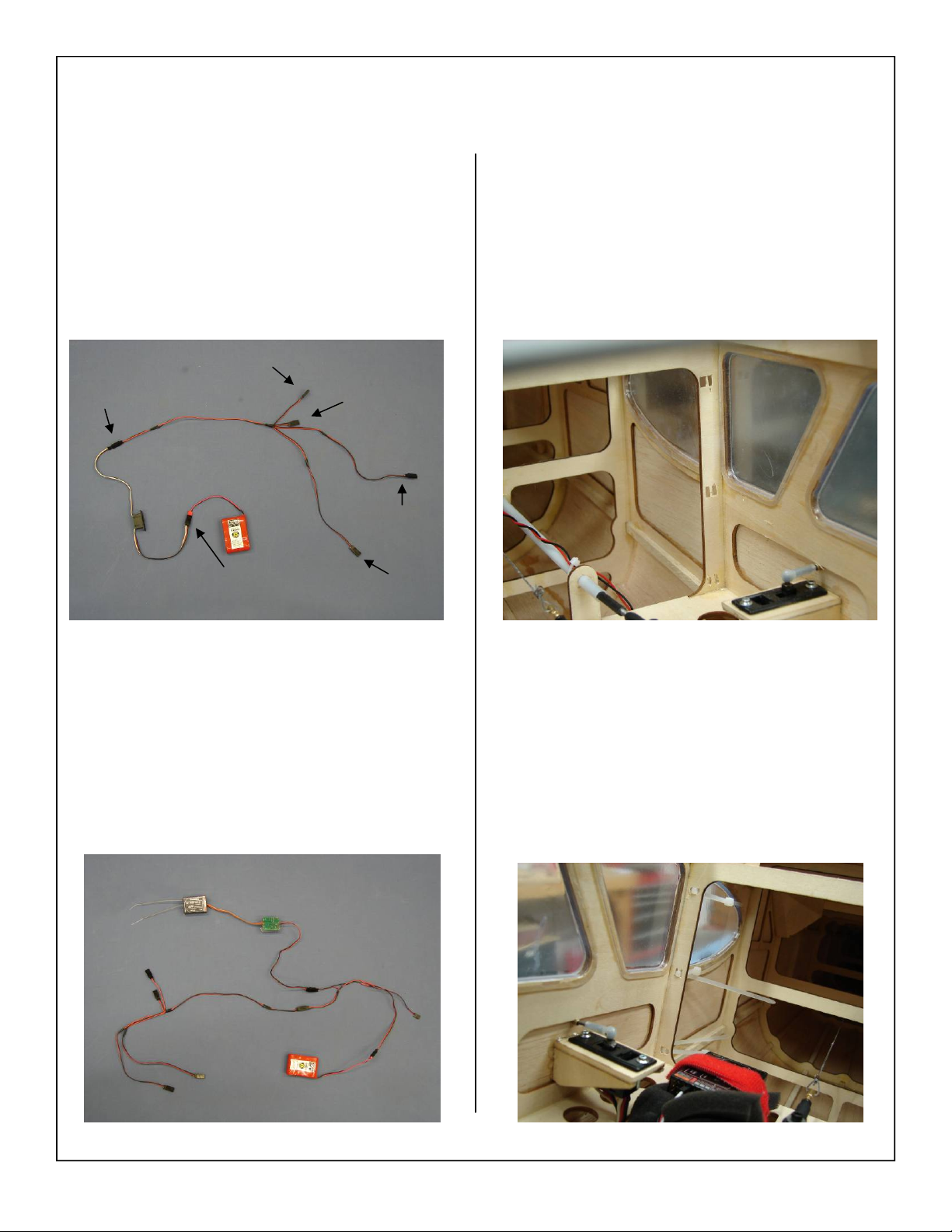
3. The manual switch lighting layout is shown below. This setup will be used for an external
lighting switch.
Tail
Switch
Switch
Beacon
R. Wing
L. Wing
5. The rear bulkhead of the fuse has 3 small holes
laser cut on both sides of the fuse. These 3 holes
are to allow the zip ties to pass through and hold
the aileron, flap, and wing tip light extensions
for a clean installation.
4. The electronic switch setup is shown below. Follow the same wiring diagram as shown in the
above step using an electronic switch as shown.
6. Slide a zip tie through each of the 3 precut holes
as shown below.
75
Page 76
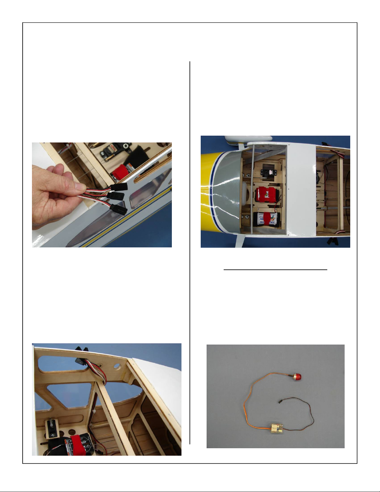
7. Gather the aileron, flap, and wing tip nav light
extensions as shown.
9. Follow the same steps for the remaining side of
the fuse. Finished radio installation shown below.
8. Place extensions on the bulkhead and tighten zip
ties. Allow approximately 2 1/2 inches of the
extensions to protrude over the top of the bulkhead and out the side of the fuse as shown.
Optional Beacon Kit Installation
1. Gather the optional Beacon kit shown below.
This kit can be purchased separately from
Aeroworks.
76
Page 77
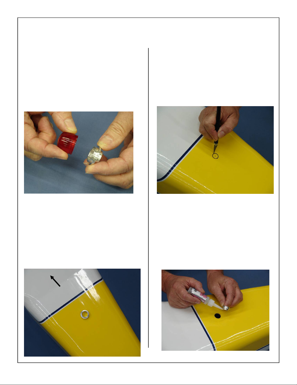
2. Remove the lens from the top of the beacon as
shown below.
4. Use a hobby knife to remove the covering and
wood for the beacon.
3. Place the beacon lens mount on the center of the
fuse behind the wing, and mark its location with
a felt tip pen as shown below.
Nose
5. Use thick CA to glue the beacon lens mount to
the fuse as shown below.
77
Page 78
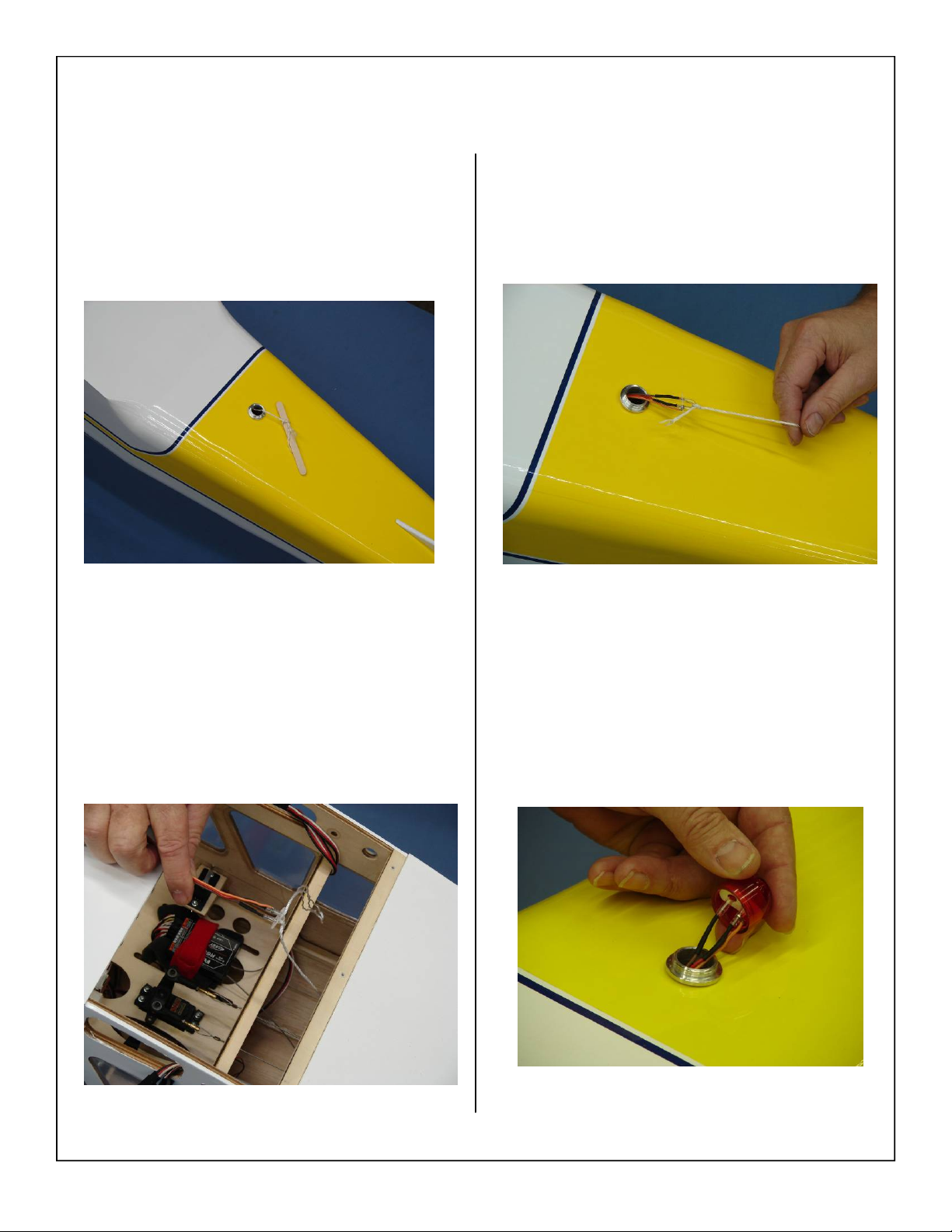
6. Pass a string through the beacon mount hole into
the radio compartment as shown below.
8. Pull the beacon light and wiring through the fuse
and out the beacon mount hole as shown below.
7. Tie the beacon light and wiring to the string as
shown below.
9. Remove the string and install the beacon light
lens cover onto the light and then onto the beacon lens mount.
78
Page 79
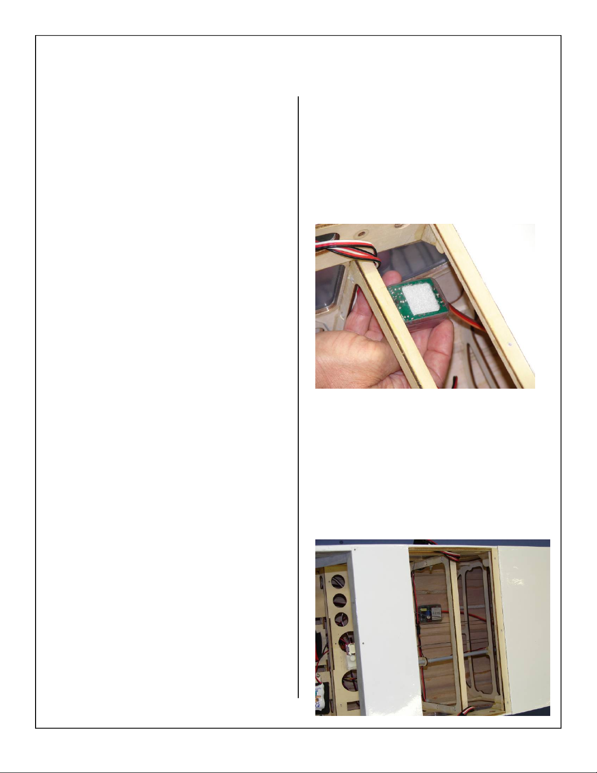
10. Use Velcro or double sided tape to hold the beacon control box in place.
11. Place the beacon control box at the bottom of the
fuse as shown.
79
Page 80
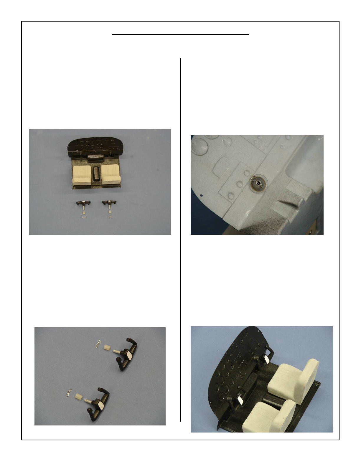
Cockpit Assembly/Installation
1. Locate the included cockpit kit as shown below.
3. Slide the control yoke through the predrilled
hole in the dash, slide the spacer onto the mounting rod and attach the cotter pin as shown.
2. Gather the following items for the cockpit assembly, (2) Control yokes, (2) Control yoke
spacers, and (2) cotter pins as shown below.
4. Finished cockpit assembly shown below.
80
Page 81
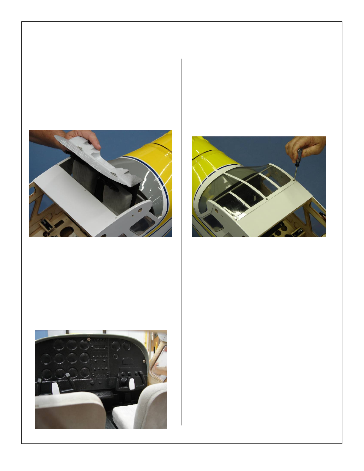
5. Slide the cockpit back into the fuse as shown
below.
Note: Be careful not to scratch the felt lining on the
inside of the fuse.
7. Reinstall the canopy using the provided mounting screws.
6. Screw the cockpit assembly into place using the
screws removed during the beginning of assembly.
81
Page 82
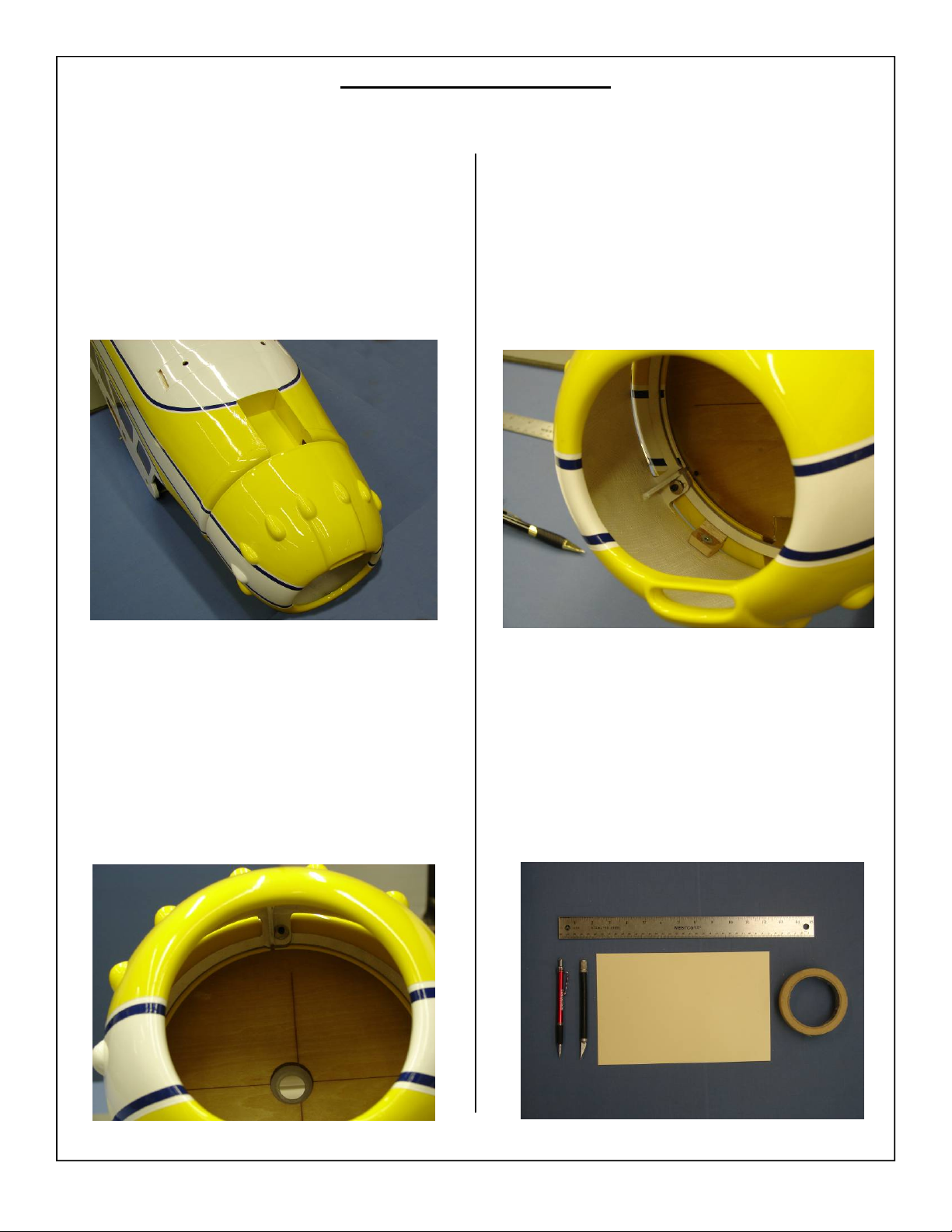
COWL INSTALLATION
1. Cowl installed on fuse as shown below. There
are two mounting options which will depend on
engine selection. These two options will be outlined in the following steps.
3. The bottom mounts for the cowling have two
mounting locations. The airplane comes setup
for a blind style mounting for bolts to pass
through the cowl ring. If these bolts are blocked
by the engine external mounts will be used. The
mounting block and blind nuts have been installed and all that is required is to drill holes in
the cowl for the mounting bolts. This decision
will be based on the engine selection.
2. The top mounting hole will be used regardless of
engine selection.
4. Gather the materials as shown below. Template
material, hobby knife, ruler, tape, marker and
pencil.
82
Page 83
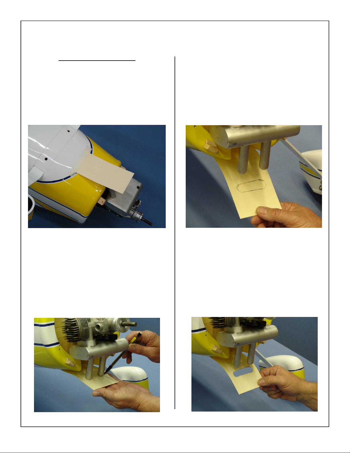
2 Stroke Cowl Installation
5. Tape the provided template material to the bottom of the fuse as shown below.
7. Remove the template and use a hobby knife to
cut out the muffler exit opening as shown.
6. Trace around the muffler being careful to keep
the template in the same location.
8. Check the fit of the template at this time. It may
be necessary to make small adjustments to the
cutout to get it to fit properly.
83
Page 84
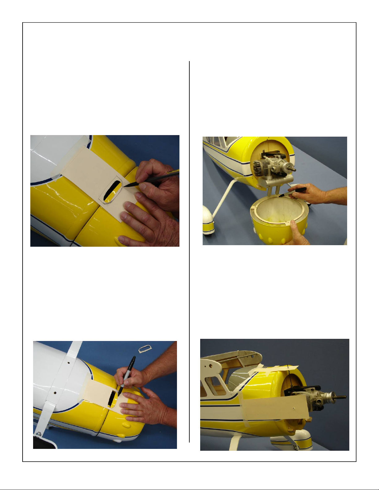
9. Trace around the template as shown below. It
may be necessary to increase the size of the cutout to aid in cowl installation.
11. Mark the location of the inner cowl ring as
shown. This portion of the cowl ring will be removed. The removal of the cowl ring will not
weaken the cowl or its mounting areas.
10. Align template with bottom of cowl. Use a felt
tip marker to transfer the template cutout pattern
to the cowl and mark cut location.
Note: Pay close attention to the marker you
choose. Some permanent markers may not
be easily removed. Also, When using
rubbing alcohols or other paint removers,
always test on painted parts before using!
12. Cut a strip of the template long enough to reach
the glow plug on the engine. Tape this strip to
the side of the fuse and mark the location of the
plug (if not using a remote glow plug). Also use
this method to locate the needle valve adjustment screw.
84
Page 85
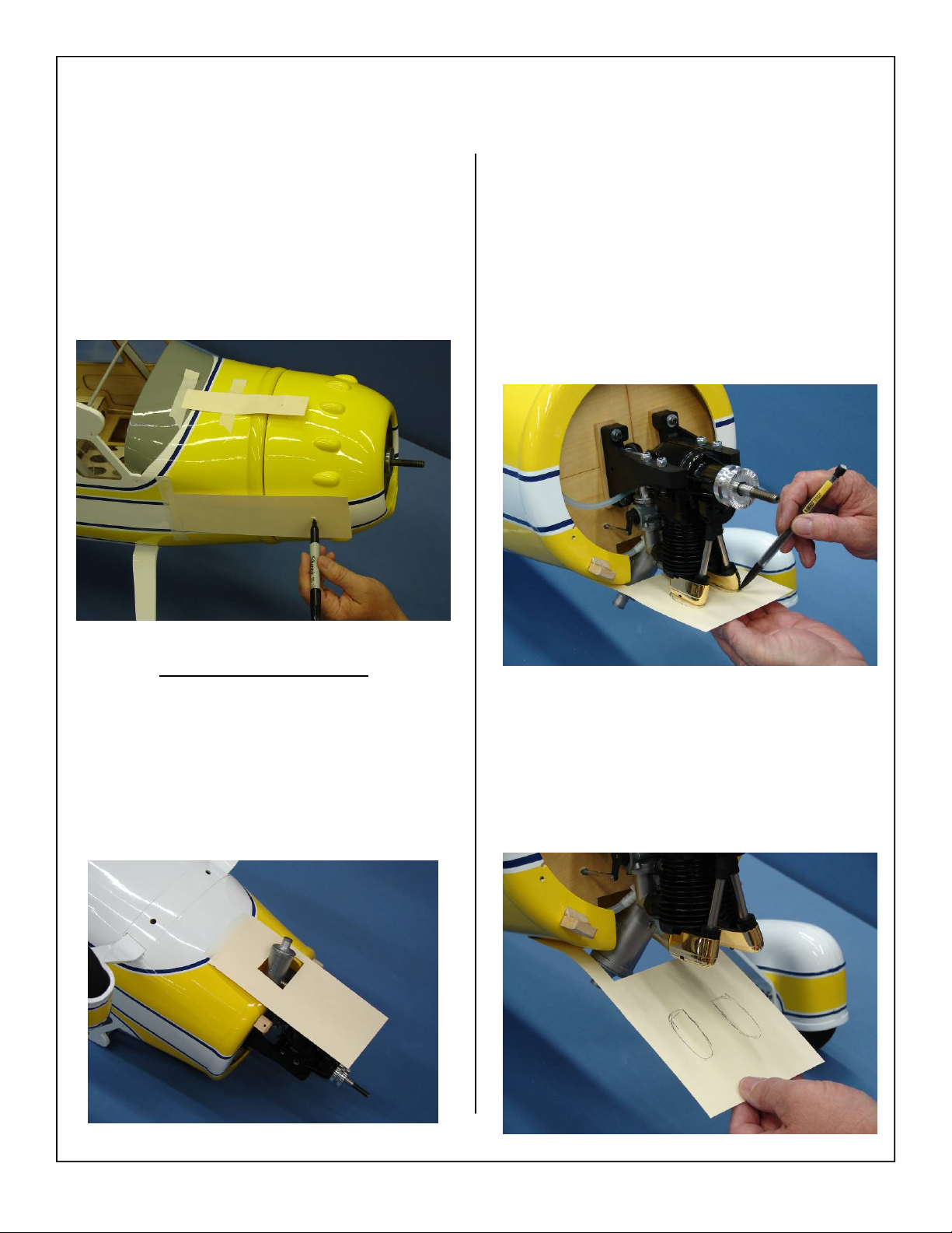
13. Bolt the cowl in place and slide the template
over it. Use a pen to transfer the location of the
cutout onto the cowl.
14. Cutout the marked area just like the previous
steps.
2. Trace around the valve covers being careful to
keep the template in the same location.
4 Stroke Cowl Installation
1. Tape the provided template material to the bottom of the fuse as shown below. Cut out access
hole to fit muffler.
3. Remove the template and use a hobby knife to
cut out the valve cover exit opening as shown.
85
Page 86
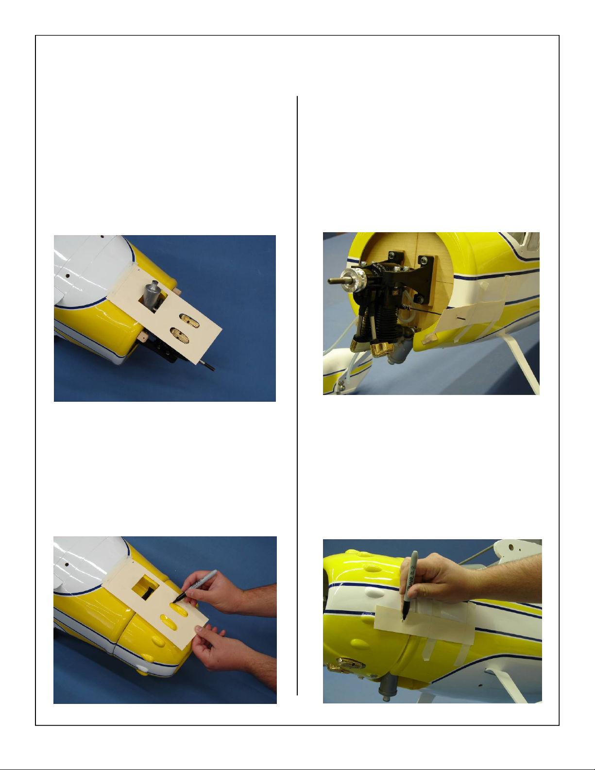
4. Check the fit of the template at this time. It may
be necessary to make small adjustments to the
cutout to get it to fit properly.
6. Cut a strip of the template long enough to reach
the needle valve on the engine. Tape this strip to
the side of the fuse and mark the location of the
needle valve. Also use this method to locate
glow plug.
5. Align template with bottom of cowl. Use a felt
tip marker to transfer the template cutout pattern
to the cowl and mark cut location.
Note: Pay close attention to the marker you
choose. Some permanent markers may not
be easily removed. Also, When using
rubbing alcohols or other paint removers,
always test on painted parts before using!
7. Bolt the cowl in place and slide the template
over it. Use a pen to transfer the location of the
cutout onto the cowl.
8. Cutout the marked area just like the previous
steps.
86
Page 87
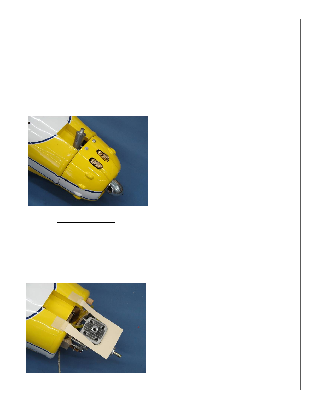
9. Finished cowl installation shown below.
Gas Cowl Installation
1. Use the steps included for the 2 and 4 stroke
cowl cutting directions to cut the cowl for the
Gas engine installation.
87
Page 88
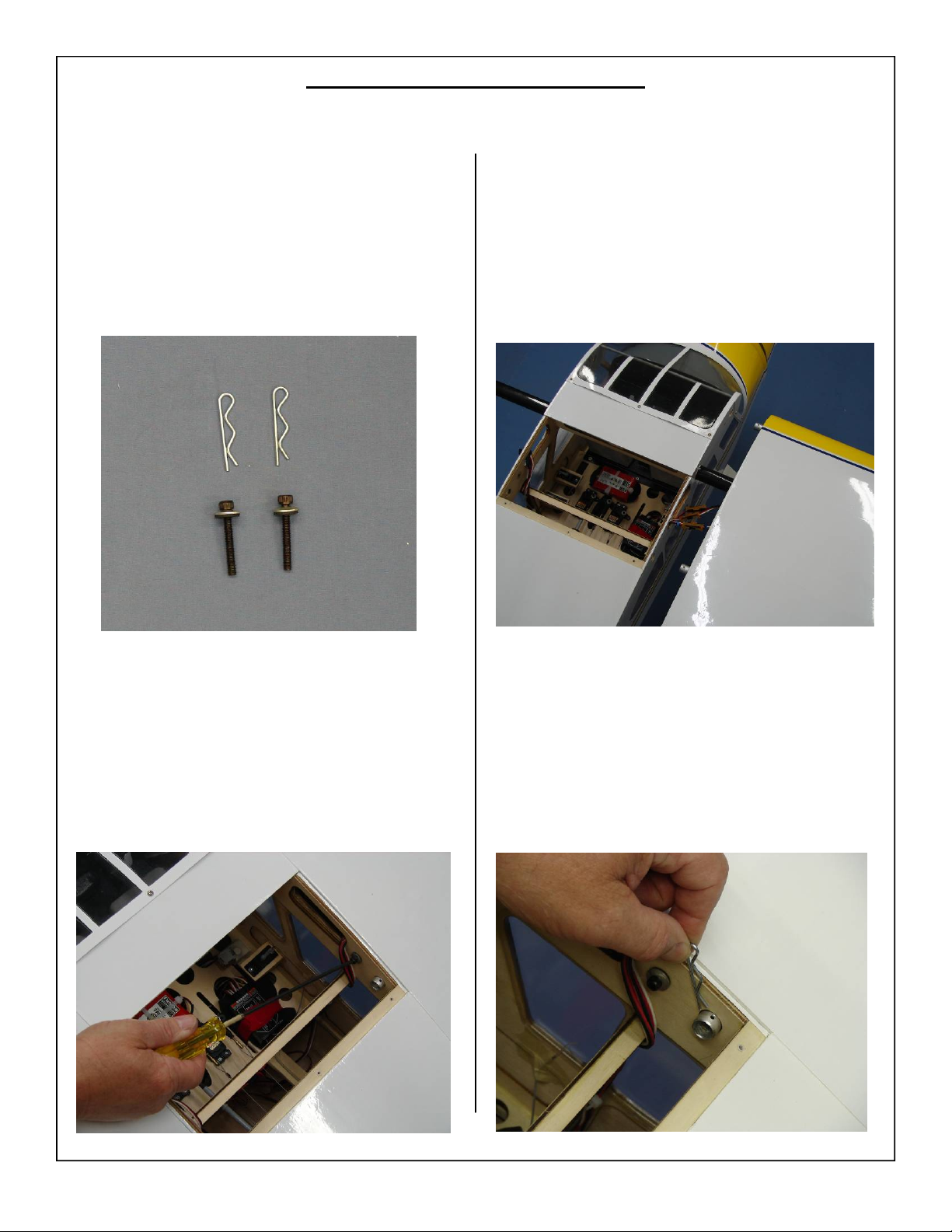
PRE-FLIGHT PREPARATION
1. Gather (2) 8-32 wing mounting bolts, (2) #8 rubber backed washers and (2) hairpins for preparation of mounting the wings.
3. Secure the aileron, flap, and lighting connectors
with Aeroworks Safety Clip. Ensure the connectors will not come apart from vibration or light
tension.
2. Slide the wing tube in the fuse wing tube sleeve.
Slide the wings on the wing tube and plug in the
aileron, flap, and light servo connectors. Slide
the rubber backed washers on the wing mounting bolts and insert bolts through the fuse side
and into the wing root blind nuts. Tighten
snugly but do not over tighten and crack the fuse
or wing root wood.
4. Install hairpins into rear aluminum anti-rotation
wing dowels to provide additional security.
88
Page 89
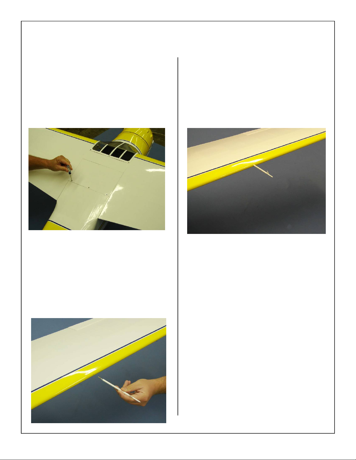
5. Install the top hatch using the 3 supplied mounting screws as shown below.
7. Screw the pitot tube in place, it is recommended
that the pitot tube be removed for transport to
protect it from damage.
6. Locate the predrilled pitot tube hole in the left
wing as shown below,
89
Page 90
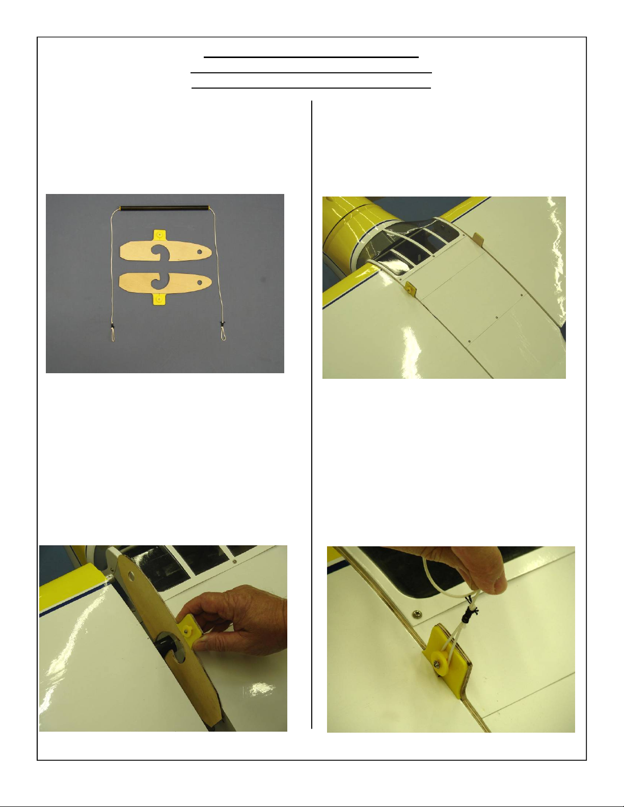
Center Of Gravity– CG Buddy
5 5/8” Back From The Wing Leading Edge
Measured From the Root End of the Wing
1. Aeroworks has included the new CG Buddy
with the Cessna 195. This handy tool will allow
the builder to balance the airplane without the
need for an assistant.
2. Gather the CG buddy as shown below:
3. Slide wings away from fuse and install the CG
Buddy on the wing tube and front rotation dowel as
shown. The cable attachment should be on the top
side of the wing. Make sure the CG Buddy is securely latched to the wing tube and dowel before
moving further.
4. Slide wing back against the fuse as shown below.
5. Install CG Buddy on the opposite wing using
the same methods described above.
6. Attach loop to cable attachment as shown below.
7. Insure both wings are pushed firmly against
fuse.
90
Page 91
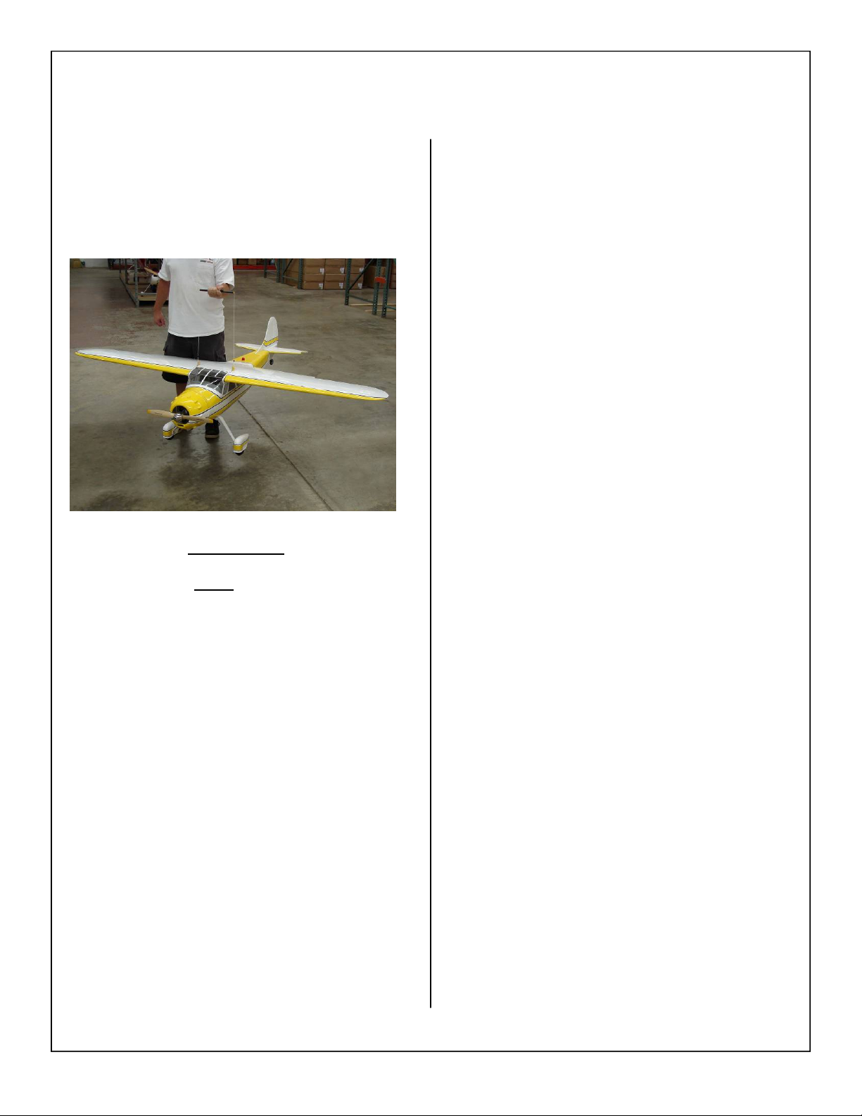
8. Lift airplane from center handle as shown, plane
should sit level when lifted. Balance the Cessna
195 without fuel in the tank with the batteries in-
stalled and READY TO FLY. Try to balance the
model by moving the batteries and receiver before
adding any ballast.
IMPORTANT
The CG Buddy is not
adjustable and is set to bal-
ance the airplane at the recommended CG of 5 5/8”
back from the leading edge at the wing root this is just
a starting point and can be adjusted as the pilot be-
comes familiar with the airplane.
91
Page 92
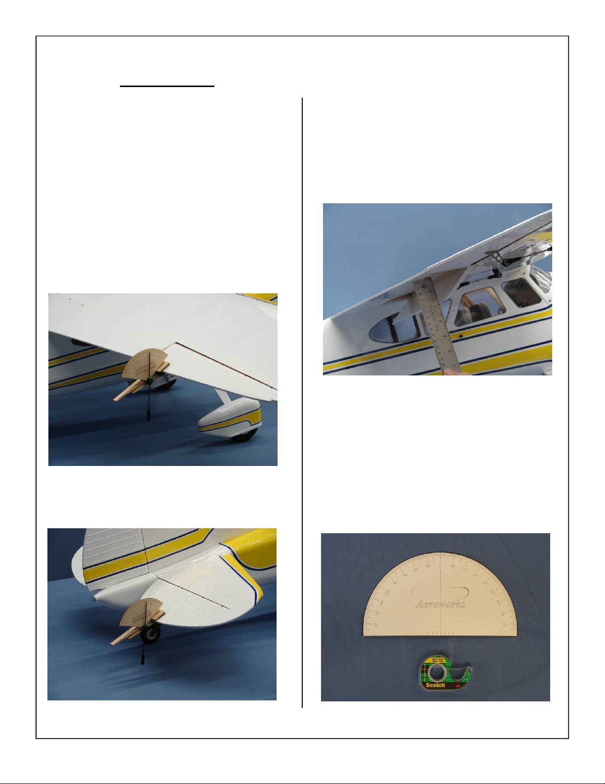
Control Throws
1. The amount of control throw should be adjusted
using mechanical means as much as possible and
then electronically with the radio. The control
throws are shown in degrees and inches of deflection measured at the widest point of the control
surface for both low and high rates.
2. Use the supplied flight control deflection meter to
measure the throws in degrees
of the aircraft until the fuselage is parallel to
the table top.
3. Use the widest part of the aileron to measure the
aileron throw in degrees.
. Prop up the tail
5. A ruler will be needed to measure the deflection
of the flaps.
4. Use the widest part of the elevator to measure the
elevator throw in degrees.
6. Gather the Rudder Deflection Meter (Supplied)
and scotch tape.
92
Page 93
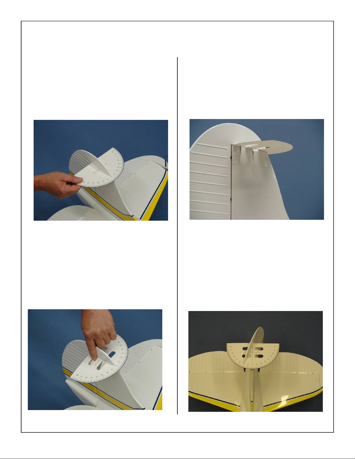
7. Slide the deflection meter under the rudder boost
tab.
9. Secure the tabs to the fin using scotch tape.
8. Center the deflection meter on the rudder using
the centering marks on the meter to aid with
alignment. Bend the precut positioning tabs down
around the fin.
10. Degrees are measured at the tip of the boost tab
as shown below.
93
Page 94
Control Throw Deflection Table
Low Rate
Aileron 10˚ up 20˚ up
10˚ down 20˚ down
Rudder 10˚ left 25˚ left
10˚ right 25˚ right
Elevator 10˚ up 20˚ up
10˚ down 20˚ down
Flap 3/4” down 1 1/2” down
We recommend 15% Expo on low rates, 30%
expo on high rates as a starting point. You a can
adjust from there to suit your own flying style.
High Rate
Preflight Checks
Center of Gravity: Check CG is set properly.
Engine: The engine should run smoothly at all
throttle settings with smooth transition from
idle to full throttle without stalling or hesitation. Do not fly an unreliable engine. Read
engine instructions including break in and tuning completely.
Prop balancing: Ensure prop is properly balanced
prior to mounting on engine.
Flight Controls: Ensure all flight controls are
free from binding and are centered. Check
that all hinges are tight and will not pull out.
Control linkages must be rigid and tight and
have no slop. Confirm proper direction of ailerons, rudder, and elevator. Experienced flyers have lost airplanes due to reversed ailerons. Right roll is right up, left down. Left roll
is left up, right down.
Batteries: Transmitter, ignition and receiver bat-
teries are fully charged.
Fasteners: Check all engine bolts, wing bolts,
hatch bolts, servo screws, control horn bolts,
wheel collars, and clevis keepers are tight and
secure.
Covering: Check all covering and seams are
sealed and secure.
Radio: Check trims set to neutral and controls
centered. Check rate and condition switches
set properly. Check the receiver antenna is
fully extended and not reversed on it self.
Range check: Do a range check with and without
the engine running in accordance with the radio manufacturer instructions. If there is insufficient range or a large reduction with the
engine running, do not fly until it is resolved!
Fuel: Fill the fuel tank before each flight.
94
Page 95

1.80-30cc Cessna 195 ARF-QB NOTES
___________________________________________________________________________
___________________________________________________________________________
___________________________________________________________________________
___________________________________________________________________________
___________________________________________________________________________
___________________________________________________________________________
___________________________________________________________________________
___________________________________________________________________________
___________________________________________________________________________
___________________________________________________________________________
___________________________________________________________________________
___________________________________________________________________________
___________________________________________________________________________
___________________________________________________________________________
___________________________________________________________________________
___________________________________________________________________________
___________________________________________________________________________
___________________________________________________________________________
___________________________________________________________________________
___________________________________________________________________________
__________________________________________________________________________
95
 Loading...