

Page 1
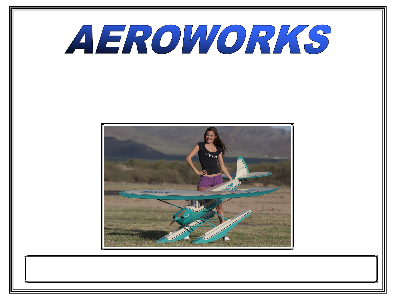
30cc BRAVATA ARF-QB
(Quick Build)
ASSEMBLY MANUAL
AEROWORKS
4903 Nome Street, Denver, CO. 80239 - Phone 303-371-4222 - Fax 303 -371-4320
E-mail - [email protected]
Page 2
CONTACT INFORMATION TABLE OF CONTENTS
WARRANTY
Page
Aeroworks Contact Information …………….. 2
Introduction …………………………………… 2
Warranty Information ………………………... 2
Kit Contents …………………………...………. 3
Items Needed To Complete …………………… 4
Tightening and Re-shrinking Covering ……… 6
Checking Glue Joints ….………………………. 7
Aileron/Flap Servo Assembly ……………...….. 8
Aileron/Flap Pushrod Installation ……………..11
Final Aileron/Flap Servo Installation.……….... 13
Stabs/Elevator Assembly………………………. 15
Vertical Fin/Rudder Assembly …………………18
Elevator Servo/Linkage Installation ….………..22
Rudder Servo/Pull-Pull Assembly……………...24
Tail Wheel Installation …………………………27
Landing Gear/Wheel Pant Installation ………. 29
Engine Installation …………………………….. 32
Ignition Installation ……………………………. 34
Throttle Servo & Choke Installation ………..... 37
Fuel Tank Assembly ……………...……………. 41
Fuselage Bottom Hatch Installation ..………… 45
Cowling Installation …………………………… 45
Radio Installation …………………………….... 48
Decal Installation ………………………………. 50
Side Window/Windshield Installation ….…..… 51
Preflight/Field Assembly………………….……. 53
Control Throw Deflection Table …………...… 54
Measuring Control Throws …………………… 55
Checking Center of Gravity …………………… 56
Flying the 30cc Bravata ………………………... 58
4903 Nome Street
Denver, CO 80239
Phone: (303) 371-4222
Fax: (303) 371-4320
Website: www.aero-works.net
E-mail: [email protected]
Tech Support: [email protected]
INTRODUCTION
Thank you for choosing the Aeroworks
30cc Bravata. We put great effort into making
this plane the best model you will ever build and
fly. Aeroworks has provided you with the highest quality kit and performance possible. We
wish you great success in the assembly and flying of your new Aeroworks 30cc Bravata ARFQB.
Great care has been taken in both the
design and manufacturing of the 30cc Bravata ARF-QB to allow for the strongest and
lightest construction possible. Only the
highest quality materials from the covering,
paint, wood and hardware have been used in
the construction of this model.
The 30cc Bravata ARF-QB has been
individually hand built, covered and painted
by trained and experienced craftsmen with
over 25 years of manufacturing experience.
Using CAD design, laser cut technology and
jig-built
production.
assures accuracy in all stages of
Aeroworks manufacturing guarantees this kit to
be free from defects in both material and workmanship at the date of purchase. This warranty
does not cover any component parts damaged by
use or modification. In no case shall Aeroworks
liability exceed the original cost of the purchased kit. Further, Aeroworks reserves the right
to change or modify this warranty without notice.
In that Aeroworks has no control over the final
assembly or materials used for final assembly,
No liability shall be assumed nor accepted for
any damage resulting from the use by the user of
the final user-assembled product. By the act of
using the user-assembled product, the user accepts all resulting liability. Aeroworks does not
accept any responsibility for structural failure.
Warranty Period
It is important to notify Aeroworks of any
damage or problems with the model within
30 days of receiving your airplane to be covered under warranty. All returned parts must
be shipped in their original shipping boxes
and insured for full replacement value. If
you wish to return this aircraft for any reason a 15% restock fee will be charged to the
customer. In addition the customer is responsible for all return shipping cost and all
prior shipping cost will not be refunded.
Parts will be fixed or replaced once the
original item is returned at the owner’s expense. It is the decision of Aeroworks if the
item is to be replaced or repaired.
Aeroworks cannot insure the skill of the
modeler and can not influence the builder
during the construction or use of this aircraft, and therefore, will not be accountable
for any property damage, bodily injury or
death caused by this aircraft.
2 Aeroworks 30cc Bravata Assembly Manual
Page 3
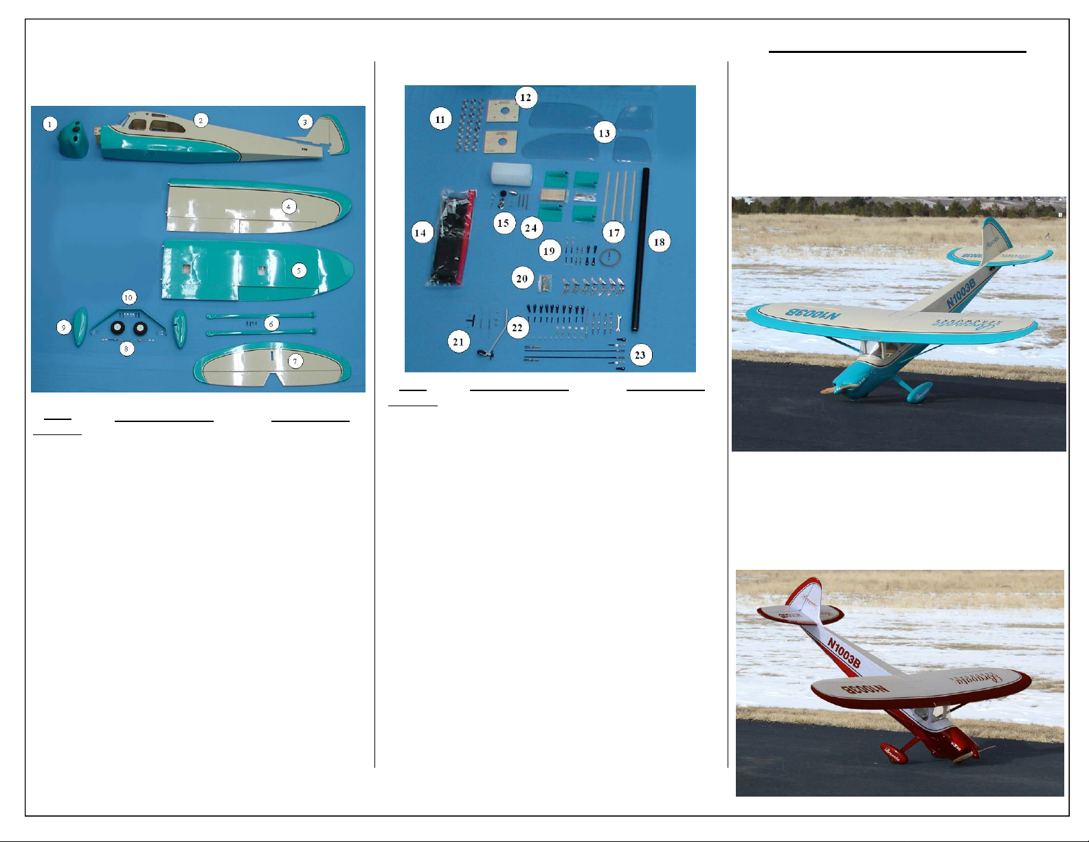
KIT CONTENTS MAIN
ASSEMBLEY
KIT CONTENTS SUB
ASSEMLEY
ULTRACOTE™ COLORS
Your model is covered with Ultracote™ covering. In
case of repairs, the colors are:
Turquoise/Cream Scheme
Turquoise #898
Cream #887
Black #874
Item
Number
Item
Number
1
2
3
4
5
6
7
8
9
10
1
2
3
4
5
6
7
8
9
10
Item Description
Turquoise/Cream
Cowl
Fuse (No Windshield)
Vertical Fin w/ Rudder
Right Wing
Left Wing
Wing Struts w/ Hardware
Horizontal Stab w/ Elevator
Main Wheel Set w/ Axles
Wheel Pants w/ Hardware
Aluminum Landing Gear
Deep Red/Cream
Cowl
Fuse (No Windshield)
Vertical Fin w/ Rudder
Right Wing
Left Wing
Wing Struts w/ Hardware
Horizontal Stab w/ Elevator
Main Wheel Set w/ Axles
Wheel Pants w/ Hardware
Aluminum Landing Gear
Part Number
ABRTC30CO
ABRTC30FW
ABRTC30VR
ABRTC30RW
ABRTC30LW
ABRTC30WS
ABRTC30HE
ABRTC30MW
ABRTC30WP
ABRTC30AL
ABRDRC30CO
ABRDRC30FW
ABRDRC30VR
ABRDRC30RW
ABRDRC30LW
ABRDRC30WS
ABRDRC30HE
ABRDRC30MW
ABRDRC30WP
ABRDRC30AL
Aeroworks 30cc Bravata Assembly Manual 3
11
12
13
14
15
16
17
18
19
20
21
22
23
24
24
25
Spare parts can be ordered directly through Aeroworks.
Please use the part numbers and item descriptions listed in
the kit contents list above to order.
Item Description
(24) 1/4” Engine Standoffs
Motor Mounting Templates
Side Windows
Foam/Velcro Mounting Pack
15oz Fuel Tank w/ hardware
Front Windshield (Not Shown)
Balsa Stab Fillets
Aluminum Wing Tube
Rudder Pull-Pull Assembly
Control Horn Set
Tail Wheel Assembly
Ball Link/Linkage Set
Throttle Pushrod Set
Turquoise/Cream
Servo Hatch Covers w/ Plates
Deep Red/Cream
Servo Hatch Covers w/ Plates
Fuselage Top Hatch (Not Shown)
SPARE PARTS
Part Number
ABR30AS
ABR30MT
ABR30SW
ABR30FV
ABR30FT
ABR30WS
ABR30SF
ABR30WT
ABR30RP
ABR30CH
ABR30TW
ABR30BL
ABR30TP
ABRTC30HC
ABRDRC30HC
ABR30TH
Your model is covered with Ultracote™ covering. In
case of repairs, the colors are:
Deep Red/Cream Scheme
Deep Red #871
Cream #887
Black #874
Page 4
HARDWARE NEEDED TO
COMPLETE
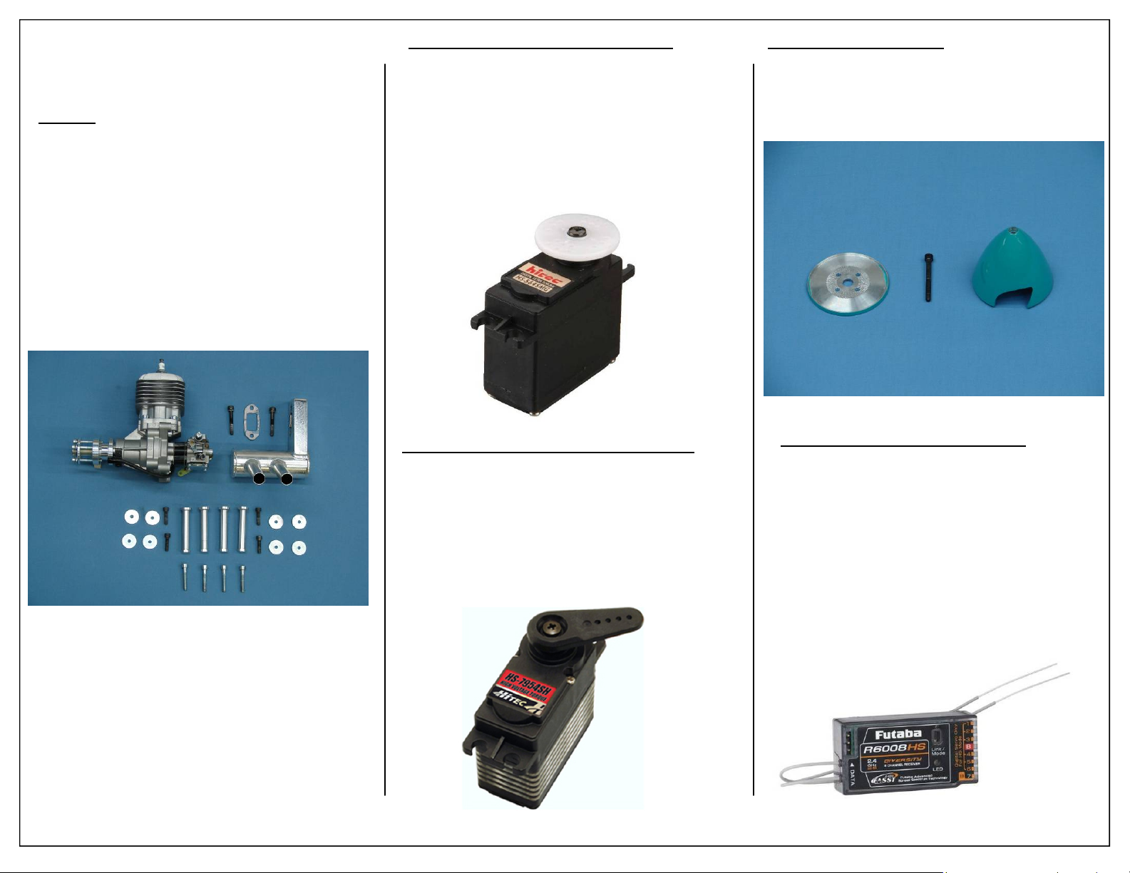
Engine:
◊ 1 - DLE 30 Rear Carb
◊ 1 - J’Tec Wrap Around Pitts Muffler
◊ 1 - Stock 60mm Standoffs Included with motor
◊ 8 - Fender Washers
◊ 8 - Motor mounting bolts
◊ 3’ - Large Gas Fuel Line
◊ 1 - 19x8 Propeller
Note: DLE 30, Propeller and J’Tec Muffler can be
purchased through Aeroworks.
Servo Option 1 : Sport Performance
Hitec 5645MG Servos may be used for sport flying.
If flying more aggressive aerobatics please see servo
option two below.
Note: Servos available through Aeroworks
◊ 6 - Hitec 5645MG Servos for flight surfaces
◊ 1 - Hitec 635HB Servo for throttle
Recommended Spinner:
◊ 1 - 3” Spinner- Aeroworks Recommended
Note: Spinner available from Aeroworks
Servo Option 2: Unlimited Performance
Electronic Accessories : Receiver
Hitec 7954SH Servos are recommended for unlimited flying. These servos will provide the best performance possible.
Note: Servos available through Aeroworks
◊ 6 - Hitec 7954SH Servos for flight surfaces
◊ 1 - Hitec 635HB Servo for throttle
A 6 or 8 channel receiver is recommended, using a
receiver with 6-8 channels will allow the builder to
mix both the aileron and elevator servo together in
the radio. Mixing these functions will result in a great
flying, well trimmed airplane.
◊ 1 - 6-8 Channel 2.4 GHz or PCM Receiver
4 Aeroworks 30cc Bravata Assembly Manual
Page 5
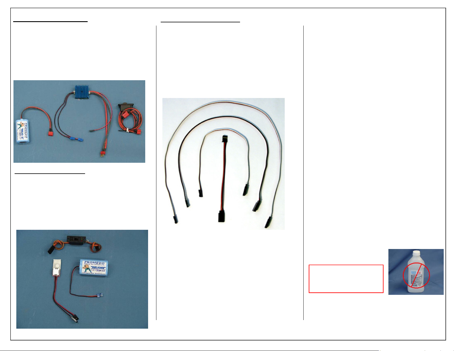
Receiver Power System :
The Aeroworks 20cc-30cc Power package is recommended. The package consists of the following
items:
◊ 1 - Fromeco Sahara Regulator Deans in 2 JR out
◊ 1 - Fromeco 2600mah Li-Ion Battery w/ Deans
◊ 1 - Smart-Fly Super Switch HD w/ Deans
Ignition Power System :
If using the DLE 30 or any other gas engine the
Aeroworks Ignition Power System is recommended
◊ 1 - Fromeco 2600mah Li-Ion Battery w/
Universal Connector
◊ 1 - Smart-Fly Ignition Regulator
◊ 1 - MPI charge switch
Recommended Extensions:
22 AWG extensions are recommended through out
the 30cc Bravata. The following sizes will be used:
◊ 1 - 36” Extensions For Elevator
◊ 2 - 18” Extensions For Ailerons
◊ 2 - 18” Extensions For Receiver to Flaps
◊ 2 - 18” Extensions For Receiver to Ailerons
TOOLS & ADHESIVES NEEDED
TO COMPLETE
• Allen wrenches US and Metric.
• Electric drill and selection of bits
• Razor saw
• Flat head screwdriver
• Hobby heat gun
• Hobby iron and covering sock
• Masking tape
• Modeling knife
• Needle nose pliers or crimping tool
• Paper towels
• Pen, pencil or felt tipped marker
• Phillips screwdriver
• Rubbing alcohol
• Ruler and tape measure
• Scissors
• T pins
• Wire Cutters
• Blue Loctite
• CA kicker (optional)
• Thick, Thin and Medium CA
• Rubbing alcohol
• Wipes
WARNING
Some rubbing alcohols
may attack painted parts.
Aeroworks 30cc Bravata Assembly Manual 5
Page 6
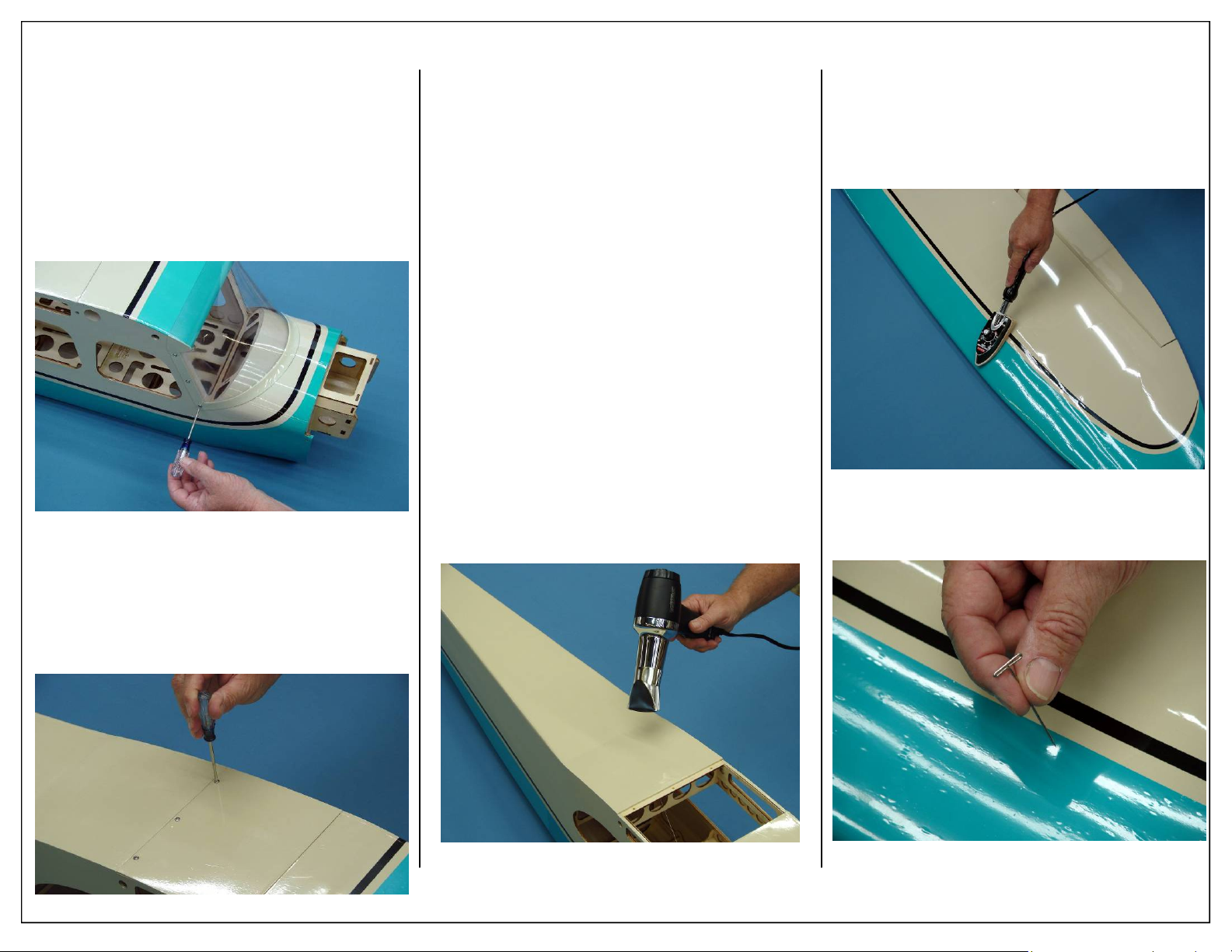
PREPARING FUSE FOR
ASSEMBLEY
1. Remove the (6) Phillips head screws that attach
the windshield to the fuse. Place the screws and
windshield in a safe place until assembly has
been completed.
Note: It is important to remove the windshield
before applying any heat to the covering.
Applying direct heat to the windshield can
damage the plastic.
2. Remove the top fuse access hatch as shown. Use
a covering iron to remove any wrinkles after it
has been removed from the fuse.
Note: It is recommended that the fuse access hatch
be placed on a flat surface and weighted down
when not bolted in place to prevent warping.
TIGHTENING AND
RESHRINKING THE
COVERING
1. Open your kit slowly and take care not to damage any parts of the kit. Remove all parts from
their plastic protective covers for inspection.
Before doing any assembly or installation of any
decals it is very important to re-shrink or retighten the already applied covering. Due to the
shipping process, heat and humidity changes
from different climates, the covering may
become lose and wrinkle in the sun. If you take
the time to re-tighten the covering, you will be
rewarded with a long lasting beautifully covered
model.
2. Use a heat gun to remove wrinkles from large
sections of covering. It is not recommended to
use a heat gun near seams or where two colors
meet.
3. Using your covering iron with a soft sock, gently
apply pressure and rub in the covering. If any
bubbles occur, your iron may be to hot. Reduce
heat and work slowly.
4. If bubbles persist, use a small pin to punch holes
in the bubble to relieve trapped air and reheat.
6 Aeroworks 30cc Bravata Assembly Manual
Page 7
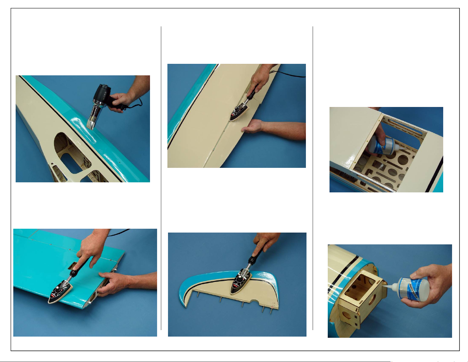
5. Use y our heat gun with extreme caution. Take
care not to apply too much heat to one area for
long periods of time. This may cause the trim
colors to over shrink and pull away leaving unsightly gaps on the color lines. The trim stripes
are especially vulnerable to over shrinking.
6. Go over all seams and color overlaps with your
sealing iron.
7. Go over all hinge gaps ensure there are no
wrinkles. Excessive wrinkles in the hinge
line can cause binding and or damage the
covering.
8. Use covering iron near seems and areas of exposed
wood. Over heating of these areas can cause the
covering to pull.
CHECKING GLUE JOINTS
1. Go over all seams and glue joints with thin CA,
this will ensure your model lasts for many seasons to come.
Note: Even if you can visibly see glue on all glue
joints it is still recommended that the joints be
reglued. Due to changes in humidity during
the life of the aircraft glue joints can separate,
it is always recommended that the glue joints
be checked before each flying session.
2. Apply Thin CA to all firewall joints. The firewall has already been fuel proofed and any additional fuel proofing is not necessary.
Aeroworks 30cc Bravata Assembly Manual 7
Page 8
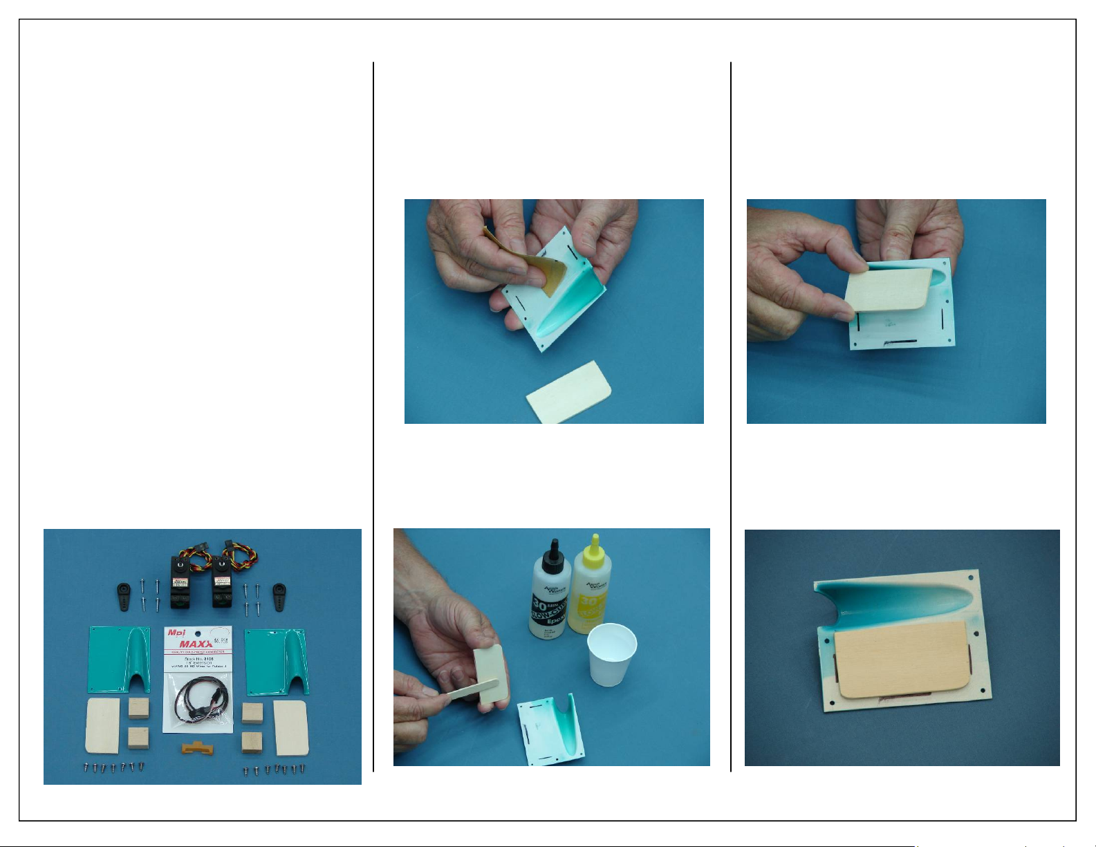
AILERON/FLAP SERVO
ASSEMBLEY
1. Gather the items shown below for the
installation of the aileron and flap servos.
Required Parts
◊ 2 - Servo Hatch Covers
◊ 4 - Servo mounting rails
◊ 2 - Plywood mounting plates
◊ 14 - Phillips head mounting screws
Required Parts-Not Included
◊ 1 - Aileron Servo
◊ 1 - Flap Servo
◊ 8 - Servo Mounting Screws (Micro Fastener
Part number STW0209 recommended)
◊ 2 - 1 1/4” Servo Arms
◊ 1 - 18” Servo Extension (Aileron Servo)
◊ 1 - Aeroworks Safety Clip
Required Tools and Adhesives
◊ Small Phillips screw Driver
◊ 80 Grit Sandpaper
◊ 30 Minute Epoxy
◊ Medium “C-Clamp”
◊ Electric Drill
◊ 1/16” Drill Bit
◊ Masking Tape
◊ Felt Tip Pen
2. Use 80 grit sandpaper to lightly scuff the area
where the plywood mounting plate will be glued
to the servo hatch cover.
Note: Take care not to sand off the pre-marked
mounting plate lines.
4. Align servo mounting plate with pre-marked
lines on the servo hatch cover as shown.
3. Apply 30 minute epoxy to the servo mounting
plate as shown.
5. Allow epoxy to fully cure before continuing
with servo hatch assembly. Masking tape can be
used to prevent the mounting plate from shifting
while the epoxy cures.
8 Aeroworks 30cc Bravata Assembly Manual
Page 9
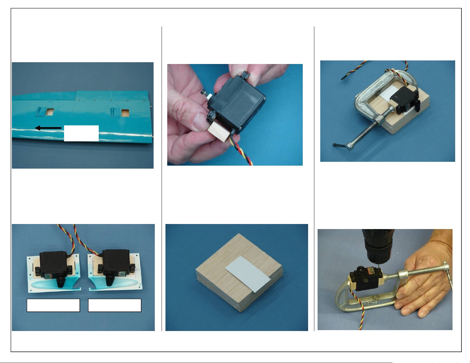
6. To ensure proper alignment, lay out the servo
hatch covers as shown. There are (2) Left and
(2) Right hatch covers supplied.
Wing Tip
8. Place the servo mounting blocks under the servo
mounting rails as shown.
10. Place servo onto card stock and clamp mounting
blocks to the servo case as shown.
7. Lay out the flap and aileron servos as shown.
Double check that the correct hatch covers are
being built for the correct wing. Both a left and
right hatch cover are shown below.
9. Before setting the servo onto a flat surface use a
piece of card stock to slightly elevate the servo.
The card stock should be the exact width of the
servo case.
11. Drill holes for servo mounting screws. Either an
electric drill or a manual hand drill will work
well in these steps.
Left Wing Right Wing
Aeroworks 30cc Bravata Assembly Manual 9
Page 10
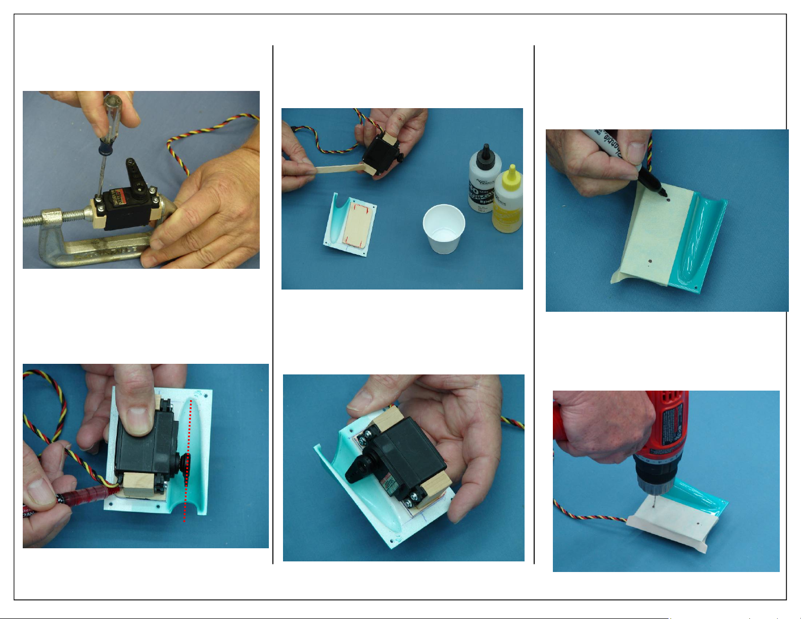
12. Install servo with servo mounting screws. Repeat servo installation process for all aileron
and flap servos.
13. Mark the location of the servo mounting blocks
onto the plywood mounting plate as shown. Ensure that the servo output shaft is centered on the
pushrod exit slot as shown below.
14. Apply 30 minute epoxy to the mounting blocks
as shown. Clean off any excess epoxy that may
get on the servo case.
15. Allow epoxy to fully cure before continuing assembly. The servo should be clamped to the
servo hatch while the epoxy cures.
16. Place masking tape on the outside of the servo
hatch as show. Mark the location of the hardwood mounting blocks. A self tapping Phillips
head screw will be installed through the hatch
and into the mounting block for additional
strength.
17. Use a 5/64” Drill bit to drill pilot holes for wood
screws.
18. Remove masking tape.
10 Aeroworks 30cc Bravata Assembly Manual
Page 11
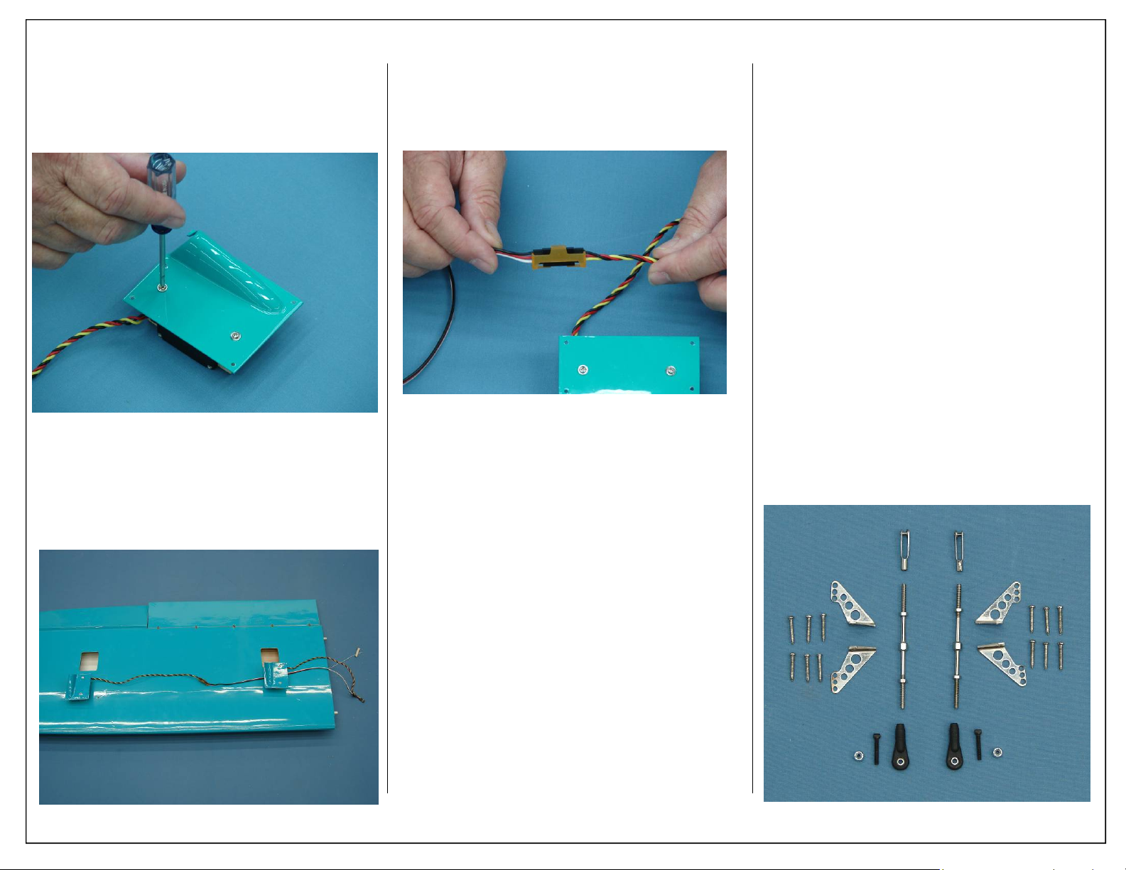
19. Use a Phillips head screw driver to install self
tapping screws. Be careful not to apply too much
force when tightening the screws as this can
cause the mounting block to fracture.
20. Lay out servos as shown. Attach an 18” servo
extension to the aileron servo.
Note: Do not install servo hatches at this time, this
will be done after the control horns have been
installed.
21. Use an Aeroworks Safety Clip to ensure the
plugs will not come apart from vibration or light
tension.
AILERON/FLAP CONTROL HORN
& PUSHROD INSTALLATION
1. Gather the aileron control linkage parts as shown
below.
Required Parts
◊ 1 - 3” Pushrod - Aileron
◊ 1 - 3” Pushrod - Flap
◊ 2 - 4-40 ball link assemblies
◊ 2 - Lock Nuts
◊ 2 - 4-40 Clevis
◊ 2 - Left control horns
◊ 2 - Right control horns
◊ 12 - T2.6x16mm Wood screws
Required Tools and Adhesives
◊ 5/64” Ball Driver
◊ 3/32” Ball Driver
◊ Pushrod Adjustment Wrench
◊ Phillips Screw Driver
◊ 1oz Bottle Gap Filling CA Glue
◊ .34oz Bottle Blue IC-Loc Thread Locker
Aeroworks 30cc Bravata Assembly Manual 11
Page 12
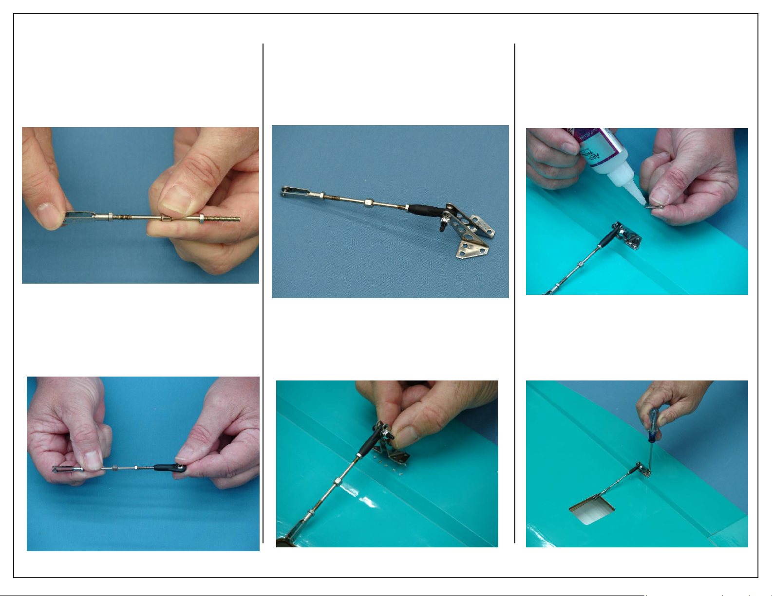
2. Thread the 4-40 clevis onto the pushrod as
shown.
Note: Pushrods have both right and left handed
threads to allow for full adjustments when
installed. The clevis must be threaded onto the
right hand thread portion of the pushrod.
3. Thread the 4-40 ball link onto the left handed
threads of the pushrod.
4. Assemble the pushrod and control horn assembly as shown. The ball link goes between the
left and right sides of the control horn sides and
is secured with a nylon lock nut. Start with the
center hole in the control horn. The ball link
may be moved up or down for more or less control throw.
5. Align the control horns over the factory drilled
holes.
6. Use a drop of thick CA glue on each screw to
prevent screws from loosening due to vibration
as shown.
Note: CA glues have a fast drying time.
Remember to work quickly.
7. Align the left and right sides of the control horns
to the mounting holes and mount using six wood
screws as shown.
12 Aeroworks 30cc Bravata Assembly Manual
Page 13
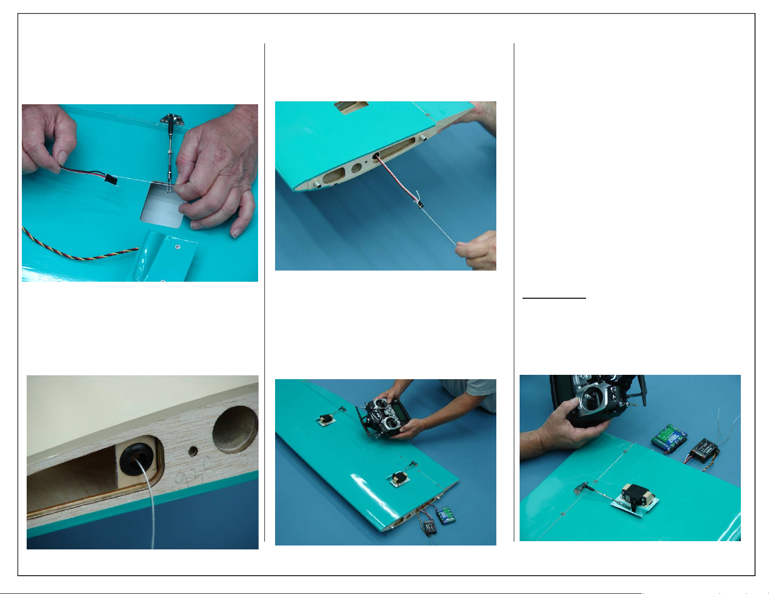
FINAL AILERON/FLAP
SERVO INSTALLA TION
1. Fasten the pull string from the servo hole to the
male plug of the servo extension.
2. Rubber grommets have been pre-installed to
help hold the servo leads in place. The pull
string should pass through this grommet allowing the servo extension to pass through once it is
pulled out the root end of the wing.
3. Pull aileron extension through root end of wing.
4. Repeat steps for the inboard servo and pull remaining extension through root end of wing.
5. Attach Aileron and flap servo to your receiver as
shown. Any 4.8-6 volt battery can be used for
servo centering/setup.
6. With the pushrod unattached to the servo arm,
power up the radio and receiver. Ensure the
servo trim and sub trim have been centered.
Both the aileron and flap servos should be setup
with the servo arm 90 degrees to the case when
in the neutral position.
7. Please refer to your radio’s manual for specific
steps on setting up dual flap and aileron servos.
It is highly recommended that this be done using
the programming capabilities of your radio and
not by using a “Y” harness.
8. Once initial programming is complete, attach the
clevis to the servo arm. A piece of fuel tubing
can be place over the clevis to prevent it from
coming loose in flight.
Note: On metal geared servos use Loctite for all
Servo arm mounting screws.
Builders Tip:
head servo arm screw with a socket head screw. This
will allow for easier removal at a later date. These
screws can be purchased from Micro Fasteners and
are part number: SCM2508
If using Hitec Servos, replace Phillips
Aeroworks 30cc Bravata Assembly Manual 13
Page 14
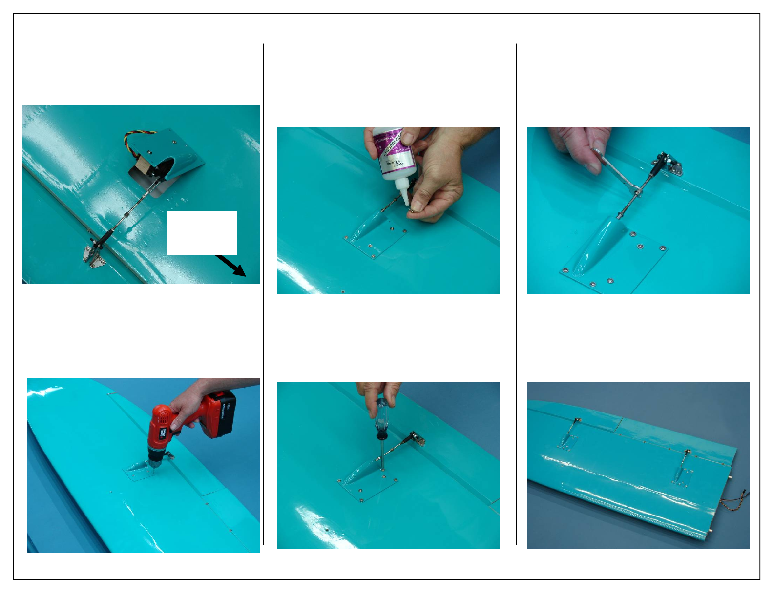
9. Install servo cover into the servo opening as
shown. Make sure that the servo cover sits flush
with the wing and that the servo exit slot is towards the wing tip.
Wing
Tip
11. Use a drop of thick CA glue on each screw to
prevent screws from loosening due to vibration
as shown.
Note: CA glues have a fast drying time.
Remember to work quickly.
13. A pushrod adjustment wrench has been included, this will allow the pushrod length to be
extended or shortened with out removing the
servo arm. Adjust the pushrod length so the control surface is neutral when the servo arm is 90
degrees to the servo case.
10. Use an electric drill with a 1/16” drill bit to drill
the servo hatch mounting hole locations as
shown.
14 Aeroworks 30cc Bravata Assembly Manual
12. Install five Phillips head screws as shown. Take
care not to over-tighten the screw as this can
damage the servo hatch cover.
14. Finished wing assembly shown below. Repeat
all previous steps for the remaining wing panel.
Page 15
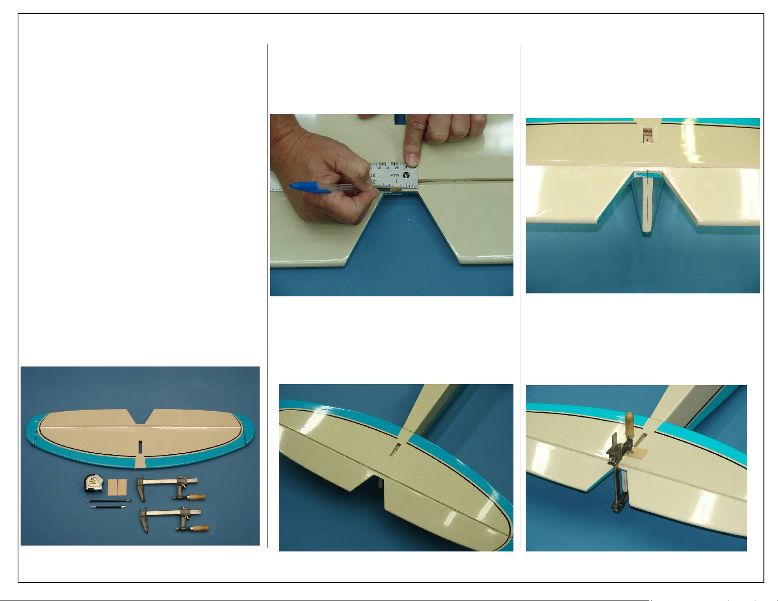
STAB/ELEVATOR
ASSEMBLEY
1. Gather the items shown below for the
installation of the Stabilizer and Elevator. The
elevator has been pre-hinged and glued to the
stab and is ready for flight. No other steps are
necessary for hinging.
Required Parts
◊ 1 - Horizontal Stabilizer w/ Elevator
◊ 2 - Stab reinforcement strips (Not Shown)
Required Tools and Adhesives
◊ Wood Slider Clamps
◊ 1/16 x 3 x 5” Hardwood sheets
◊ 30 Minute Epoxy
◊ Ball Point Pen
◊ Pencil
◊ Hobby Knife
◊ Ruler
◊ Tape Measure
2. Mark the center of the elevator joiner as shown.
3. Repeat this step for the back of the fuse, this will
help align the stabilizer for measuring.
4. Place the stab/elevator assembly on the stabilizer
cutout of the fuse as shown.
5. Align the two marks made in step 2 and 3 as
shown below.
Note: These marks are just for reference and to aid
in initial stab alignment. Once clamped in
place the stab will be aligned with the wing.
6. Use a wood clamp to temporarily hold the back
of the stab/elevator assembly in place as shown.
Use a 1/16” x 3” x 5” piece of hardwood sheet
under the clamp. This will prevent the clamp
from crushing the stab.
Aeroworks 30cc Bravata Assembly Manual 15
Page 16
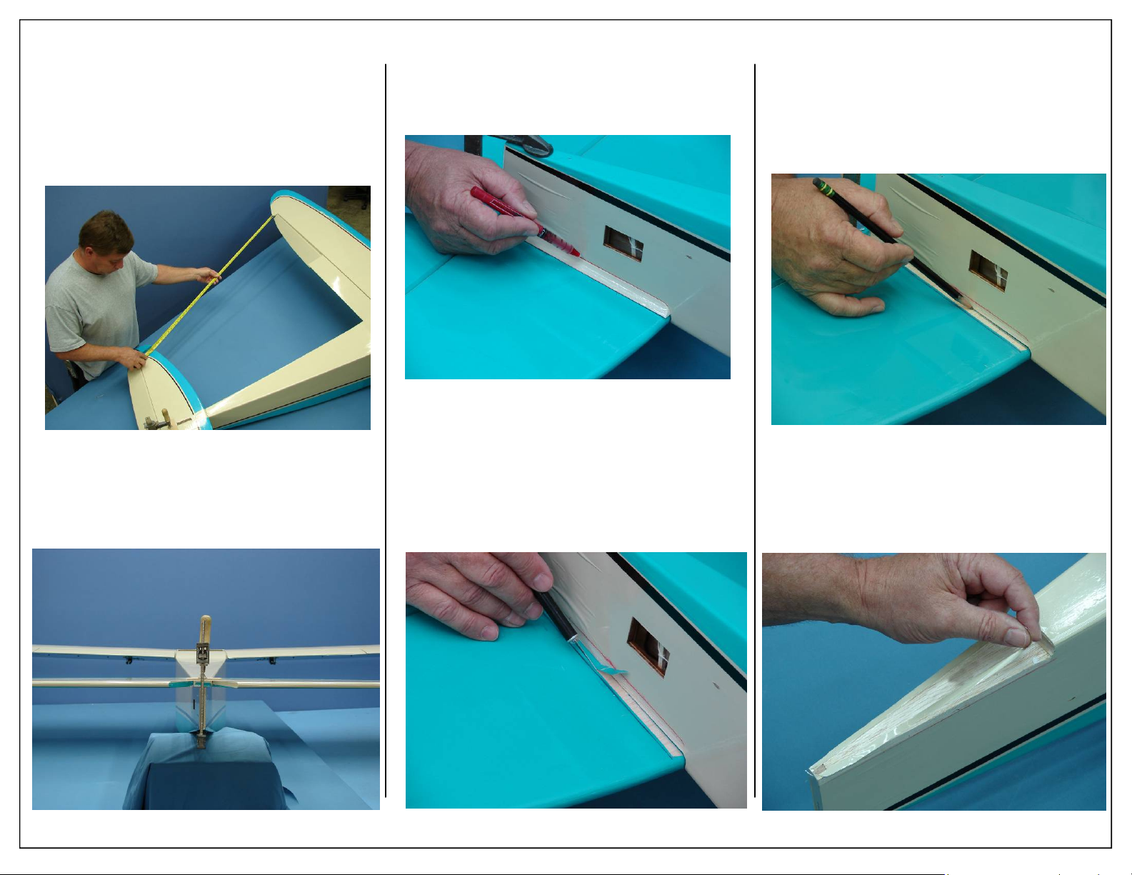
7. Using a tape measure, measure from the trailing
edge of the wing to the trailing edge of the stab
at the tip as shown. Repeat this step for the other
side of the stab. Ensure that the measurement is
identical on each side. If the stab is not straight
as compared to the wing some adjustment may
be necessary.
8. Making sure the airplane is completely level,
sight down the elevator and ensure it is level in
relation to the wing. If it is not level, it may be
necessary to slightly sand the fuse on one side.
9. Place the stab reinforcement strip against the
fuse and mark its location on both the stab and
fuse as shown.
10. Repeat for remaining side.
11. Use a hobby knife to remove the covering, cut
1/16” to the inside of the marks made in the previous step.
12. Repeat for remaining side.
Note: Take care not to cut into the underlying wood,
this may weaken the stab and can lead to an in
flight failure.
13. Using a pencil, mark the location where the stab
meets the fuse. This will help you align the stab
for final gluing.
14. Repeat for remaining side.
15. Remove any covering on the stab saddle as
shown. This will allow for maximum gluing
area.
16 Aeroworks 30cc Bravata Assembly Manual
Page 17
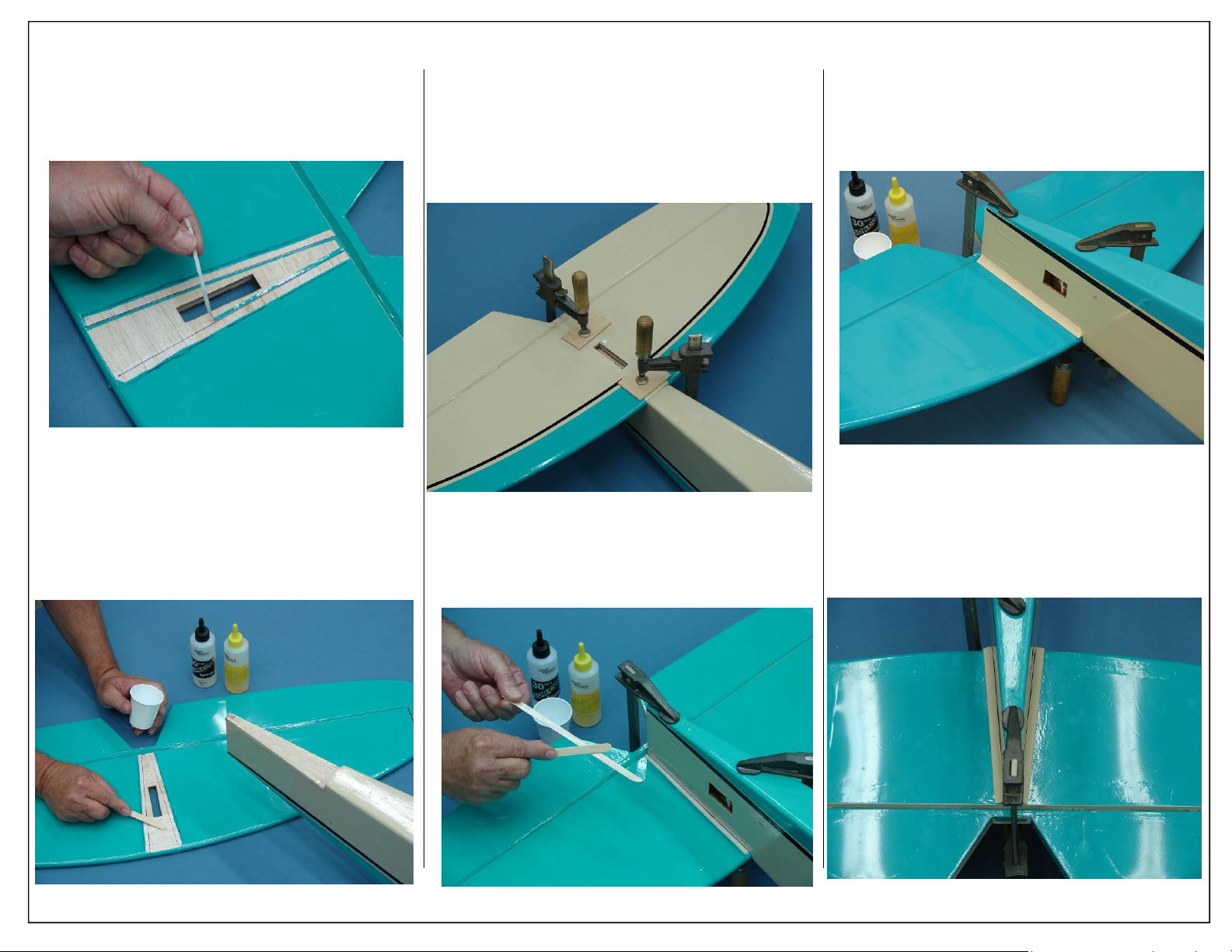
16. Remove any excess covering from the stab as
shown. There should be no covering between the
two stab reinforcement strips on the bottom of
the stab.
18. Use to clamps to firmly hold the stab in place
while the epoxy cures. Ensure the stab stays
aligned with the reference marks made in steps
13 and 14.
Note: Use rubbing alcohol to remove any excess
epoxy.
20. Place stab reinforcement strips against fuse as
shown. Make sure the reinforcement strip fully
contacts both the stab and fuse sides.
21. Repeat for remaining side.
17. Apply 30 minute epoxy between the pencil
marks made in steps 13 and 14 on the previous
page. Take care not to get any epoxy on the stab
reinforcement strips gluing area at this time.
Aeroworks 30cc Bravata Assembly Manual 17
19. Apply 30 minute epoxy to the stab reinforcement strips as shown.
22. Allow epoxy to fully cure before removing
wood clamps. It is recommended that the fuse be
kept at room temperature and allowed to dry for
an hour to allow epoxy to cure properly.
Page 18
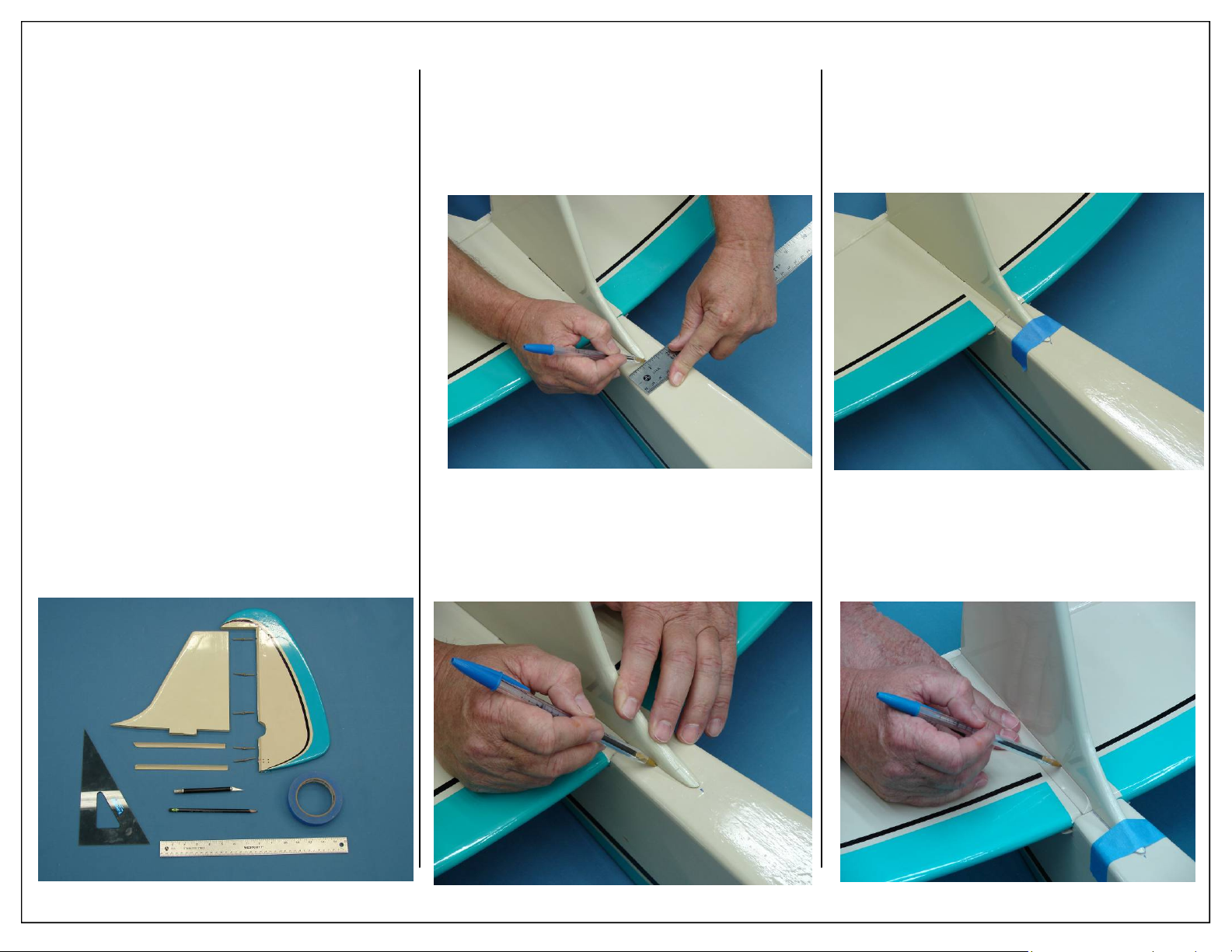
VERTICAL FIN/ RUDDER
INSTALLATION
1. Gather the items shown below for the installation of the fin/rudder.
Required Parts-Not Included
◊ 1 - Vertical Fin
◊ 1 - Rudder
◊ 5 - Hinge Pins
◊ 2 - Stab reinforcement strips
Required Tools and Adhesives
◊ Small Square
◊ Pencil
◊ Ball Point Pen
◊ Ruler
◊ Hobby Knife
◊ Masking Tape
◊ 30 Minute Epoxy
2. Place the vertical fin into the slot cut in the stabilizer as shown.
3. Measure for the center of the fuse where the vertical fin meets the fuselage.
5. Use masking tape to secure the front of the
vertical fin to the fuse. Be careful not to move
the vertical fin when taping.
4. Use a pin to mark the location of the vertical fin
on the fuse. Do not mark the stabilizer at this
time.
6. Place the stab reinforcement strips against the
vertical fin and stabilizer. Use a pen to mark
their location onto the fin and stab.
18 Aeroworks 30cc Bravata Assembly Manual
Page 19
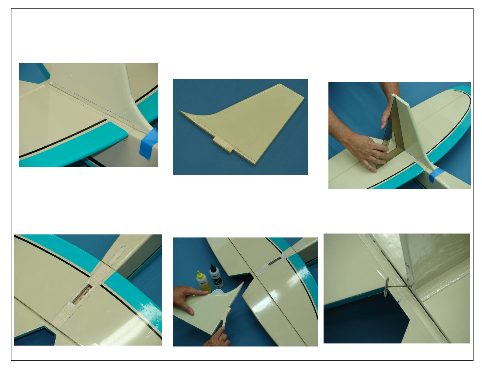
7. Remove the stab reinforcement pieces as shown.
Their location should be clearly marked by the
lines made in the previous step.
8. Use a hobby knife to remove the covering from
the fuse and stabilizer, cut 1/16” to the inside of
the marks made in the previous step.
Note: Take care not to cut into the underlying wood,
this may weaken the stab and can lead to an in
flight failure.
9. Use a hobby knife to remove the covering from
the vertical fin, cut 1/16” to the inside of the
marks made in the previous step.
Note: Take care not to cut into the underlying wood,
this may weaken the fin and can lead to an in
flight failure.
10. Apply 30 minute epoxy to vertical fin and alignment tab as shown.
11. Place vertical fin as shown. Realign the front of
the vertical fin with the reference marks made
earlier and tape in place.
12. Use a square to ensure the vertical fin is perpendicular to the stab.
13. Place a “T” pin through the trailing edge of the
vertical fin and into the stab to secure the fin
while the epoxy cures.
Aeroworks 30cc Bravata Assembly Manual 19
Page 20
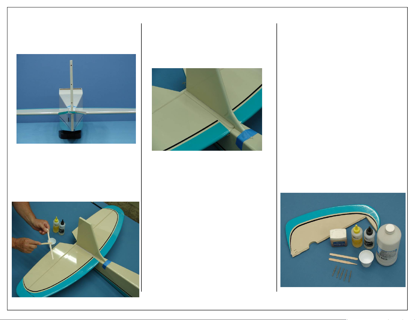
14. Allow epoxy to fully cure before continuing
with assembly. As the epoxy cure, ensure that
the vertical fin is perpendicular to the stab.
15. Apply 30 minute epoxy to the stab reinforcement strips as shown.
16. Place stab reinforcement strips against fuse as
shown. Make sure the reinforcement strip fully
contacts both the stab and fuse sides.
17. Repeat for remaining side.
RUDDER
INSTALLATION
1. Gather rudder installation items as shown
below
Required Parts
◊ 1 - Rudder
◊ 5 - Pin Point Hinges (Not Glued)
Required Tools and Adhesives
◊ 30 Minute Epoxy
◊ Mixing Sticks
◊ Mixing Cups
◊ Rubbing alcohol
◊ Vaseline petroleum jelly or light oil
20 Aeroworks 30cc Bravata Assembly Manual
Page 21
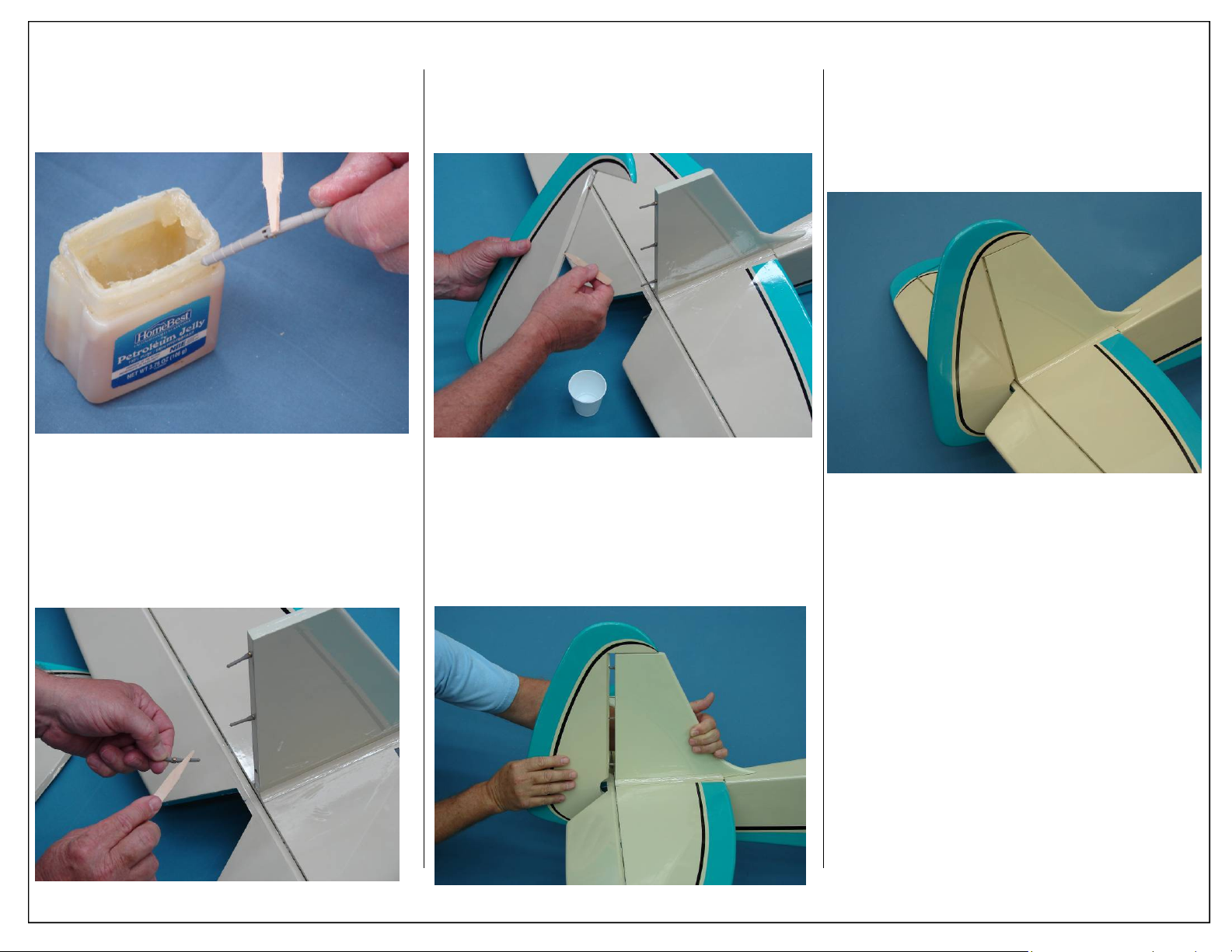
2. Prep all hinges for installation by applying
Vaseline petroleum jelly or light oil to the
hinge joint. This ensures no epoxy gets into
the hinge during assembly.
4. Mix epoxy in mixing cup and use a tapered stick
to apply the epoxy inside the pre-drilled holes in
the leading edge of the rudder.
6. Ensure there is minimal to no gap between fin
and rudder. Allow epoxy to fully cure.
Note: Ensure you have full rudder deflection
before epoxy fully cures.
3. Mix epoxy in mixing cup and apply epoxy to
one side of each hinge, insert the hinge completely into the predrilled holes in the trailing
edge of the vertical fin.
Aeroworks 30cc Bravata Assembly Manual 21
5. Carefully slide the rudder onto each hinge and
against the trailing edge of the fin. Wipe away
excess epoxy with alcohol wetted wipes.
Page 22
ELEVATOR SERVO
INSTALLATION
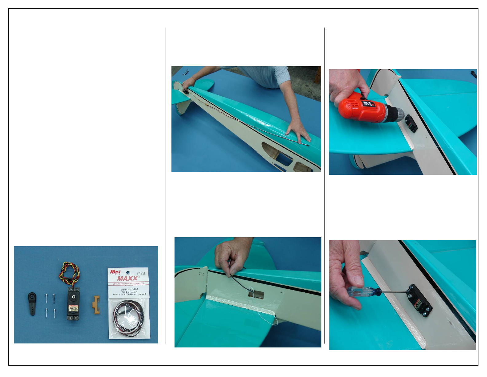
1. Gather the items shown below for the elevator
servo installation.
Required Parts
◊ 1 - Elevator Servo
◊ 1 - 1” Servo arm
◊ 1 - 36” servo extension
◊ 1 - Aeroworks safety clip
◊ 4 - Servo mounting screws (Micro Fastener
Part number STW0209 recommended)
Required Tools and Adhesives
◊ 1 - 5/64” Ball Driver
◊ 1 - 3/32” Ball Driver
◊ 1 - Pushrod Adjustment Wrench
◊ 1 - Electric Drill
◊ 1 - 1/16” Drill Bit
2. Attach 36” servo extension to servo. Use an
Aeroworks Safety Clip to ensure the plugs will
not come apart from vibration or light tension.
3. Attach elevator servo extension to pre-installed
pull string as shown.
4. Pull extension through fuse and into radio compartment.
5. Install servo in servo well with the output shaft
towards the rear of fuse as shown below.
6. Using a 1/16” drill bit, drill holes for servo
screws.
7. Install servo with servo mounting screws.
22 Aeroworks 30cc Bravata Assembly Manual
Page 23
ELEVATOR LINKAGE
ASSEMBLEY
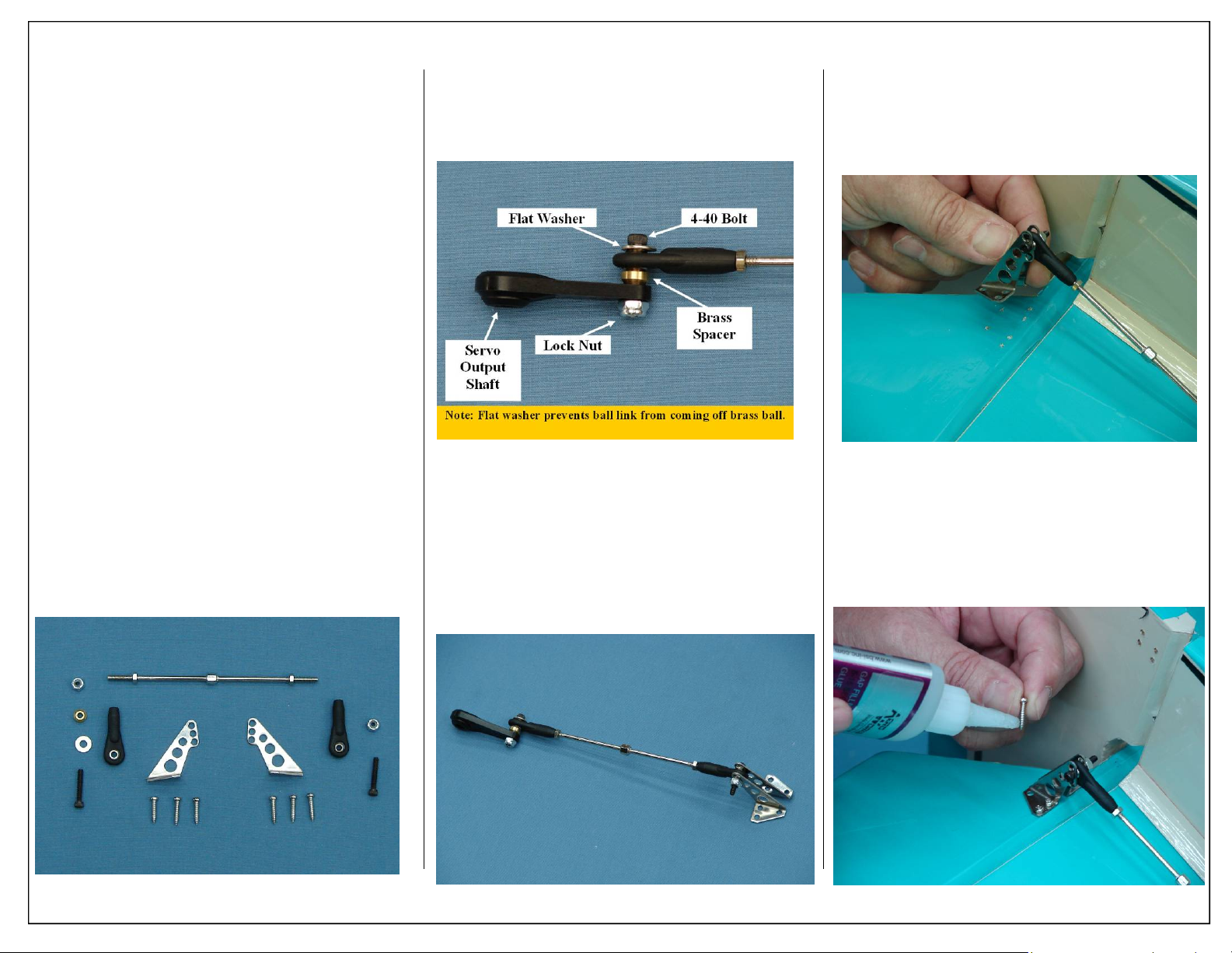
1. Gather the elevator control linkage parts as
shown below.
Required Parts
◊ 1 - 4” pushrod
◊ 2 - 4-40 ball link assemblies
◊ 1 - Brass spacers
◊ 1 - Flat washer
◊ 2 - Lock nuts
◊ 1 - Left control horns
◊ 1 - Right control horns
◊ 6 - T2.6x16mm Wood screws
Required Tools and Adhesives
◊ 1 - 5/64” Ball Driver
◊ 1 - 3/32” Ball Driver
◊ 1 - Pushrod Adjustment Wrench
◊ 1 - Phillips Screw Driver
◊ 1 - 1oz Bottle Gap Filling CA Glue
◊ 1 - .34oz Bottle Blue IC-Loc Thread Locker
2. Correct installation of ball link to servo arm
shown below.
Note: Flat washer will prevent ball link from
coming loose from brass ball.
3. Assemble the pushrod and control horn assembly as shown. The ball link goes between the
left and right sides of the control horn sides and
is secured with a nylon lock nut. Start with the
center hole in the control horn. The ball link
may be moved up or down for more or less control throw.
4. Align the control horns over the factory drilled
holes.
5. Use thick CA on each screw prior to installing to
lock screws in place.
Note: CA glues have a fast dry i ng time.
Remember to work quickly.
Aeroworks 30cc Bravata Assembly Manual 23
Page 24
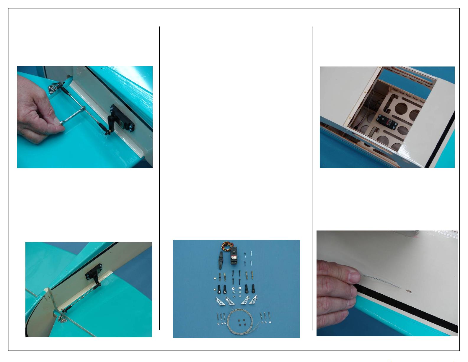
6. A pushrod adjustment wrench has been included, this will allow the pushrod length to be
extended or shortened with out removing the
servo arm. Adjust the pushrod length so the control surface is neutral when the servo arm is 90
degrees to the servo case.
7. Finished elevator servo assembly shown below.
RUDDER SERVO AND
PULL-PULL ASSEMBLEY
1. Gather the rudder servo and pull-pull parts as
shown below.
Required Parts
◊ 2 - 1x1300mm Pull-Pull cable
◊ 4 - 4-40 ball link assemblies
◊ 4 - 4-40 Bolts
◊ 2 - Brass spacers
◊ 2 - Flat washer
◊ 4 - Lock nuts
◊ 2 - Left control horns
◊ 2 - Right control horns
◊ 6 - 2x20mm Phillip head bolts
◊ 6 - 2mm Nuts
◊ 4 - 3.5x5mm Brass swage tubes
◊ 4 - 4-40 Coupler with nuts for cable
Required Parts-Not Included
◊ 1 - Rudder servo w/ Mounting Hardware
◊ 1 - 2 1/2” Double Output Servo Arm
Required Tools and Adhesives
◊ 5/64” Ball Driver
◊ 3/32” Ball Driver
◊ Wire Cutters
◊ Pliers
◊ Phillips Screw Driver
◊ 1oz Bottle Gap Filling CA Glue
◊ .34oz Bottle Blue IC-Loc Thread Locker
2. Install rudder servo, out put shafts facing the
tail, with servo mounting screws.
3. Feed the rudder cable through the pre installed
cable exit tube in the tail of the fuse toward the
front. Repeat for other side.
24 Aeroworks 30cc Bravata Assembly Manual
Page 25
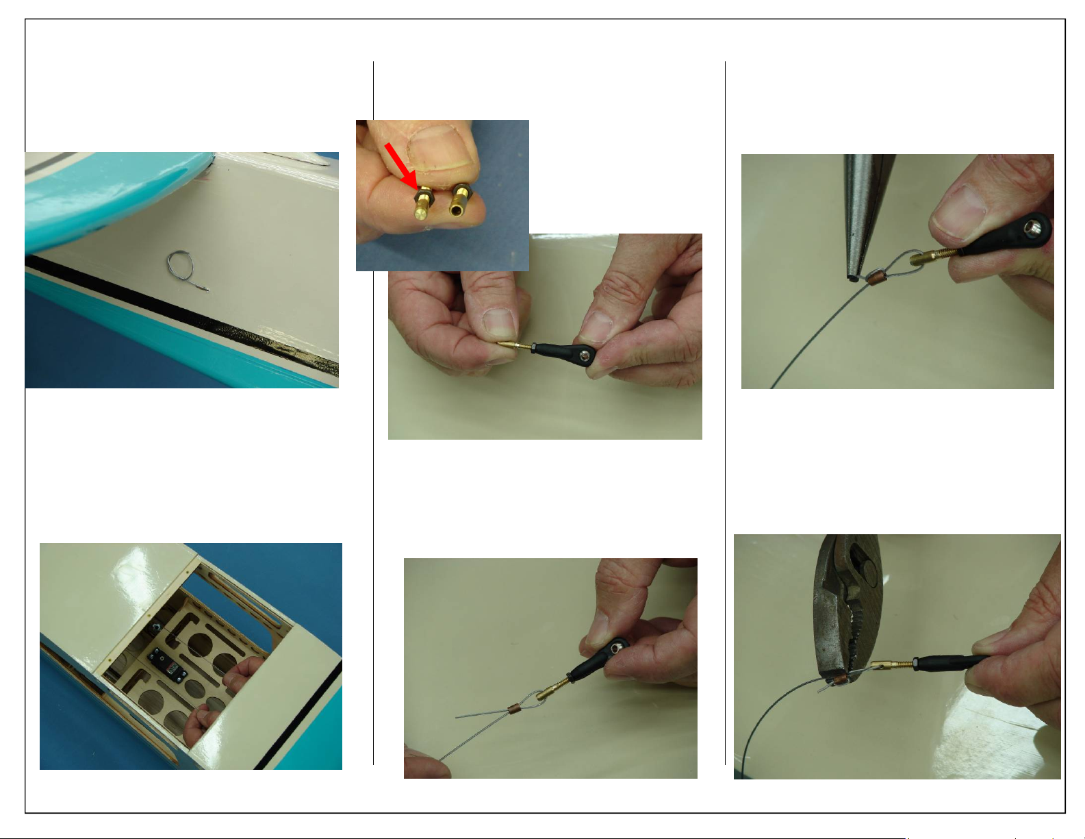
4. Loop or tape cable to fuse to prevent cable from
being pulled into fuse
5. Pull the rudder cables from the fuse tail to the
rudder servo tray. Take care not to cross the cables.
6. Thread brass coupler half way into ball link.
Note: There are two types of 4-40 couplers supplied,
two are for the throttle and choke pushrods
and four are for the pull
pull system. The couplers
with the solid base are to
be used for the pull pull
assembly.
7. Thread the brass swag tube onto the pull pull
cable followed by the threaded coupler.
8. Thread cable back through the brass swage tube
as shown.
9. Loop the cable back through the brass swage
tube and pull tight as shown.
10. Crimp the brass tube with a crimping tool or
pliers.
11. Cut off excess cable at this time.
Aeroworks 30cc Bravata Assembly Manual 25
Page 26
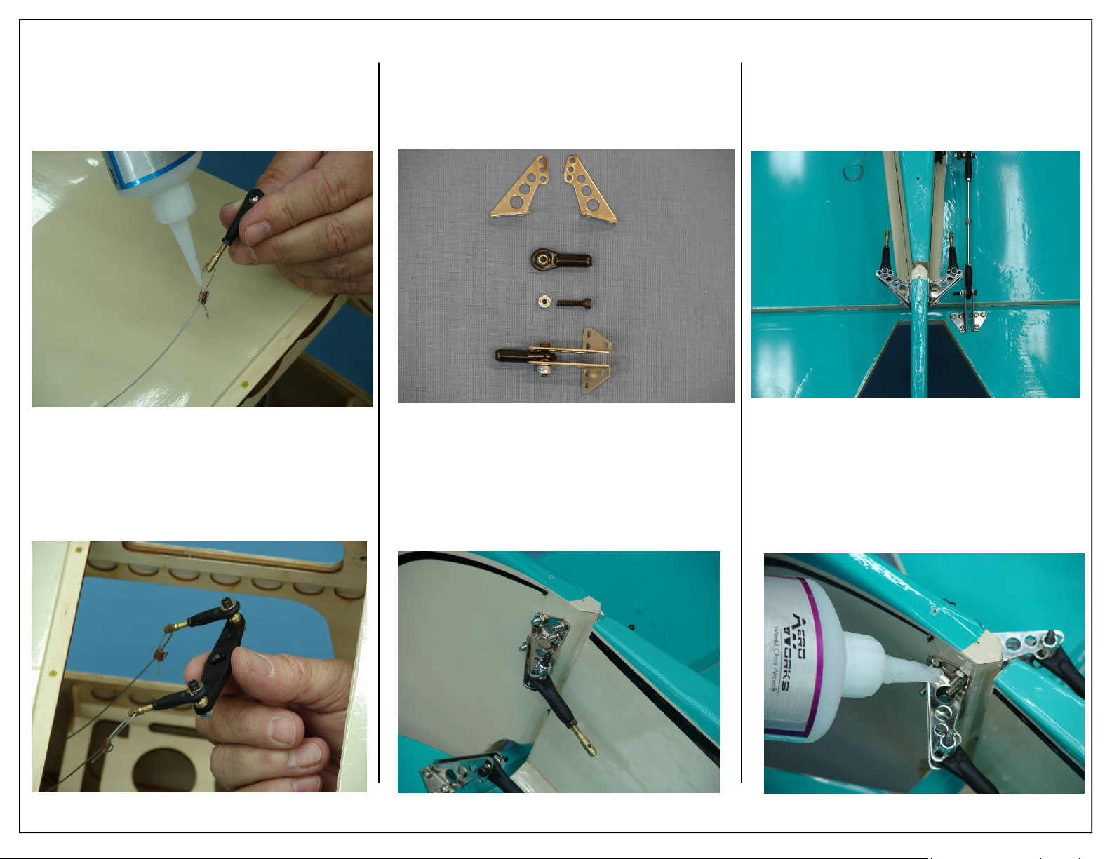
12. A drop of thin CA may be applied to the swage
tube to help secure the cable.
13. Repeat for other side rudder control linkage.
15. Assemble the ball links between the control
horns as shown. Secure with nylon lock nut.
Note: Mount ball link to inner control horn hole
to obtain full rudder deflection
18. Final control horn installation shown below.
Tighten the 2mm bolts evenly, this will prevent
the control horns from crushing the rudder.
14. Using 4-40 bolt, flat washer and lock nut, install
the ball links onto servo arm as shown below.
26 Aeroworks 30cc Bravata Assembly Manual
16. Pass the 2x20mm Phillips head bolts through
one control horn and then through the pre-drilled
holes in the rudder.
17. Install the remaining control horn and secure in
place with six 2mm nuts
19. Secure nuts with a drop of thick CA. This will
prevent them from coming loose in flight.
Page 27
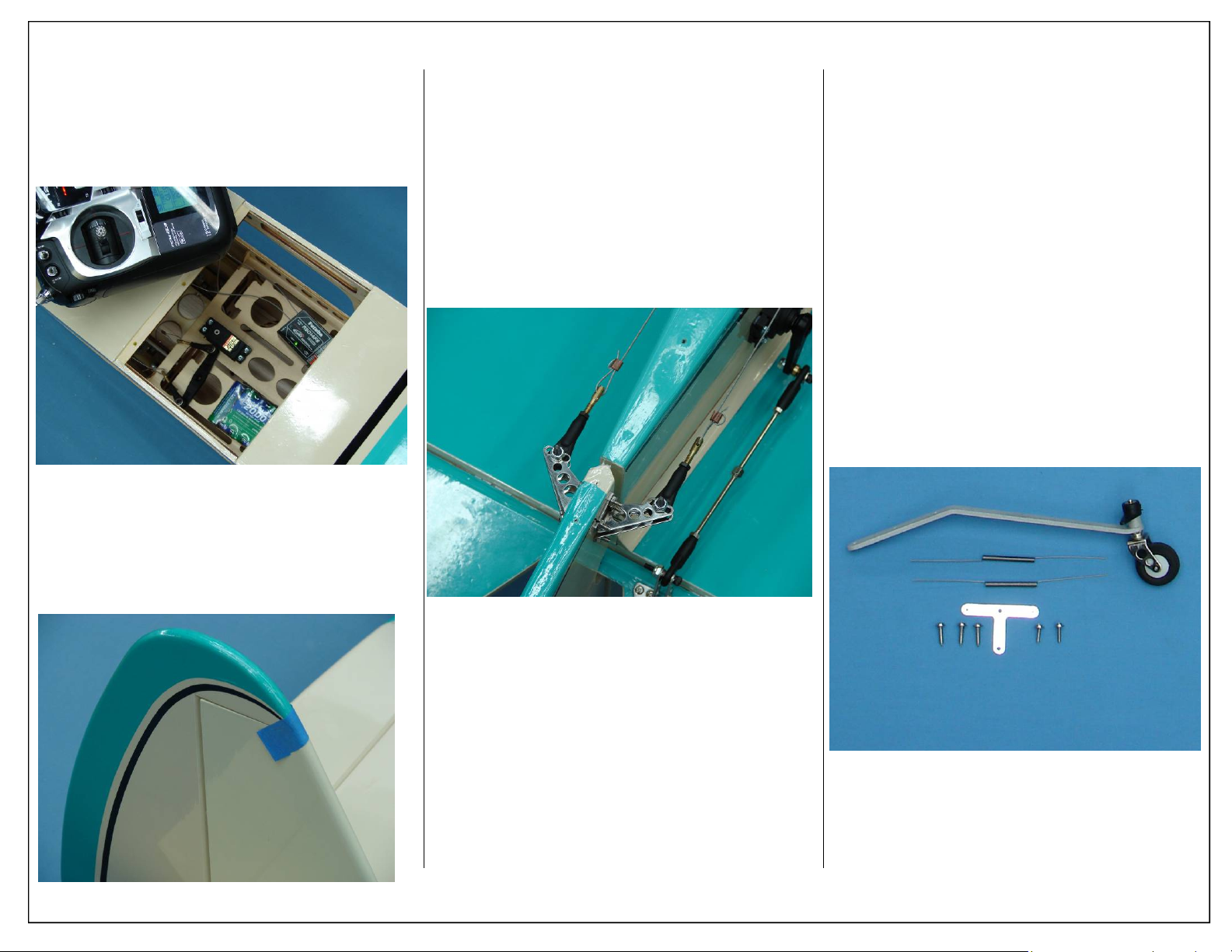
20. Plug the rudder servo into the rudder channel of
the receiver and power up. Turn on transmitter
to center rudder servo.
21. Tape the rudder balance tab to the top leading
edge of the vertical fin in the neutral position as
shown. This ensures the rudder is straight when
the cables are attached.
22. Pull cable snug and attach pull pull cable to rear
ball links.
23. Adjust the tension of the pull pull cables until
they are tight. Overly tightening cables can bind
or slow servo movement. Adjust cables to allow
for some slack as shown.
Note: Due to temperature change and normal wear,
it may be necessary to tighten the cables over
time.
TAIL WHEEL
INSTALLATION
1. Gather the tail wheel assembly items as
shown below.
Required Parts
◊ 1 - Tail wheel assembly
◊ 3 - Tail wheel mounting screws
◊ 1 - Steering tiller
◊ 2 - Tiller mounting screws
◊ 2 - Steering springs
Required Tools and Adhesives
◊ 1 - Phillips Screw Driver
◊ 1 - 1oz Bottle Gap Filling CA Glue
◊ 1 - .34oz Bottle Blue IC-Loc Thread Locker
Aeroworks 30cc Bravata Assembly Manual 27
Page 28
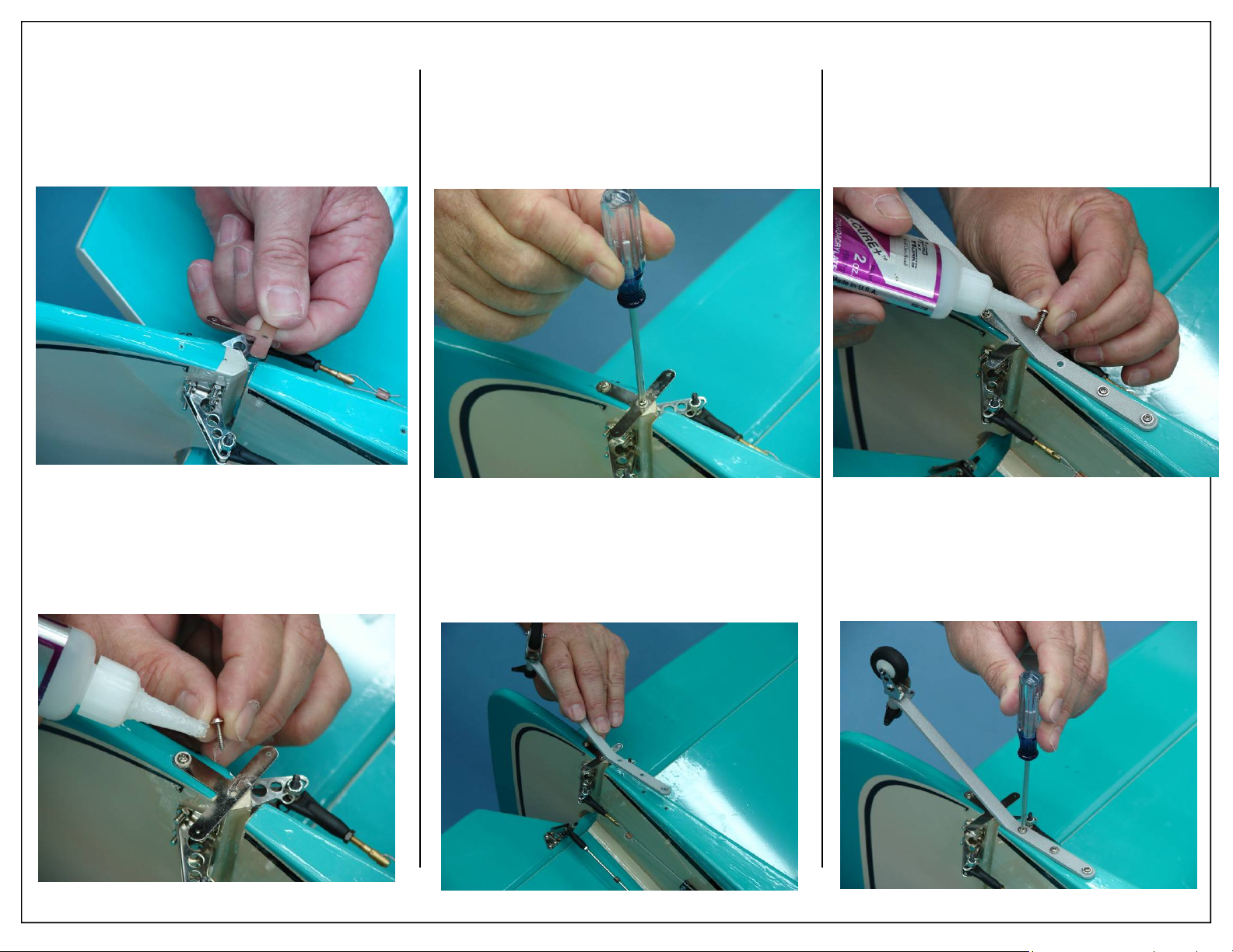
2. Place tail wheel steering tiller over the predrilled holes in the bottom of the rudder.
4. Mount the tail wheel steering tiller using two
wood screws.
6. Place a drop of thick CA on tail wheel strut
mounting screws before inserting in the predrilled mounting holes on the bottom rear of the
fuse.
3. Apply a drop of thick CA to the mounting
screws before inserting into the tiller mounting
holes.
28 Aeroworks 30cc Bravata Assembly Manual
5. Place tail wheel strut over the pre-drilled holes
in the bottom rear of the fuse.
7. Mount the tail wheel strut using three wood
screws.
Page 29
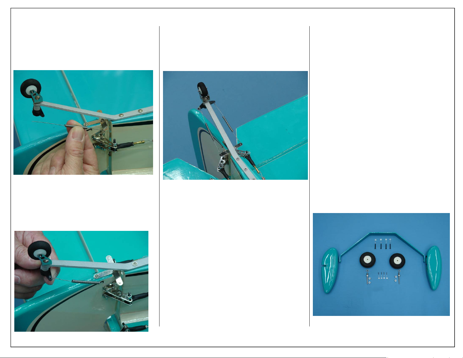
8. Tape the rudder boost tab in place to keep the
rudder aligned while tightening the steering
springs.
9. Attach the steering spring to the rudder tiller.
Center the spring between both tail wheel and
steering tillers.
10. Twist spring end tight with pliers.
11. Repeat spring installation for other side.
12. Bottom view of completed tail wheel installation.
MAIN LANDING GEAR AND
WHEEL PANT INSTALLATION
1. Gather the following items shown below for the
main landing gear assembly.
Required Parts
◊ 1 - Aluminum landing gear strut
◊ 2 - 3 1/2” Foam Tires
◊ 2 - Axles with lock nuts
◊ 4 - Wheel collars
◊ 4 - 8-32 mounting bolts
◊ 4 - 8-32 Lock washers
◊ 4 - 8-32 Flat washers
◊ 2 - Wheel pants
◊ 4 - 4-40 Bolts
◊ 4 - 4-40 Lock washers
◊ 4 - 4-40 Flat washers
Required Tools and Adhesives
◊ 1 - 9/64” Ball Driver
◊ 1 - 12mm Open End Box Wrench
◊ 1 - .34oz Bottle Blue IC-Loc Thread Locker
Aeroworks 30cc Bravata Assembly Manual 29
Page 30
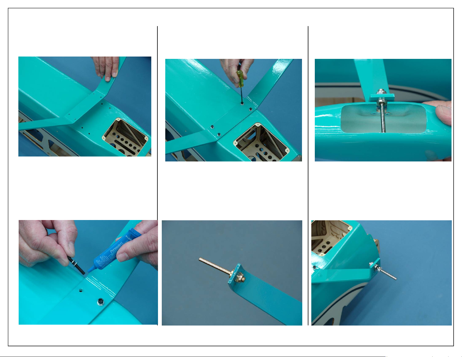
2. The tapered edge of the landing gear goes to the
back of the airplane.
4. Bolt landing gear strut to fuse with (4) 8-32 bolts
and washers.
6. Check alignment of axle with cutout in wheel
pant. Check alignment of wheel pant mounting
holes with mounting holes in gear. Securely
tighten axel to gear strut.
3. Attach the landing gear with bolt and flat
washer. Use a drop of blue Loctite on landing
gear bolts before attaching the landing gear.
30 Aeroworks 30cc Bravata Assembly Manual
5. Install the axle into the gear strut with lock nut.
Only snug tighten at this time.
7. Install inner wheel collar. Use blue Loctite on
the wheel collar set screw before final tightening.
Page 31
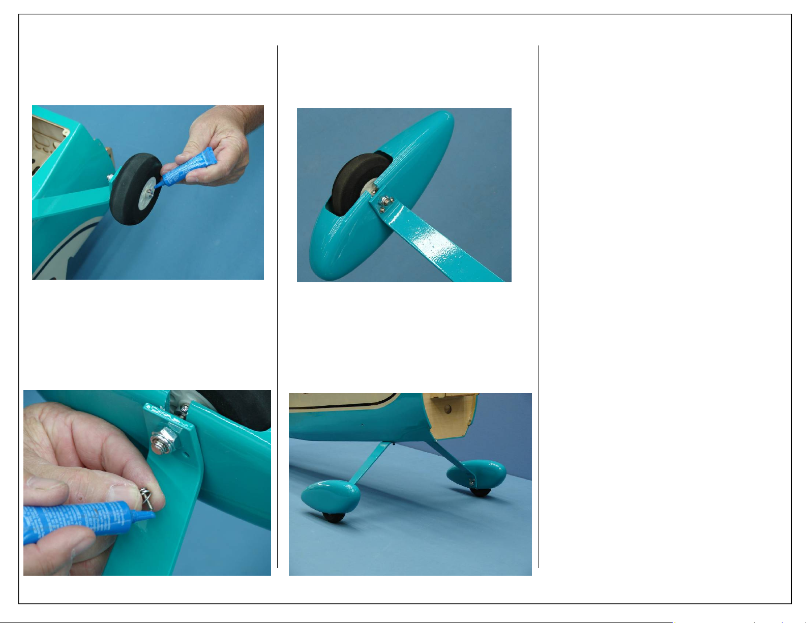
8. Install 3 1/2” wheel and outer wheel collar. Use
blue Loctite on the wheel collar set screw before
final tightening
10. Final installation of wheel pant with two mounting bolts.
9. Slide the lock washer then the flat washer on the
wheel pant mounting bolts. Use blue Loctite on
the bolts before final tightening.
Aeroworks 30cc Bravata Assembly Manual 31
11. Repeat previous steps for other wheel and wheel
pant.
Page 32
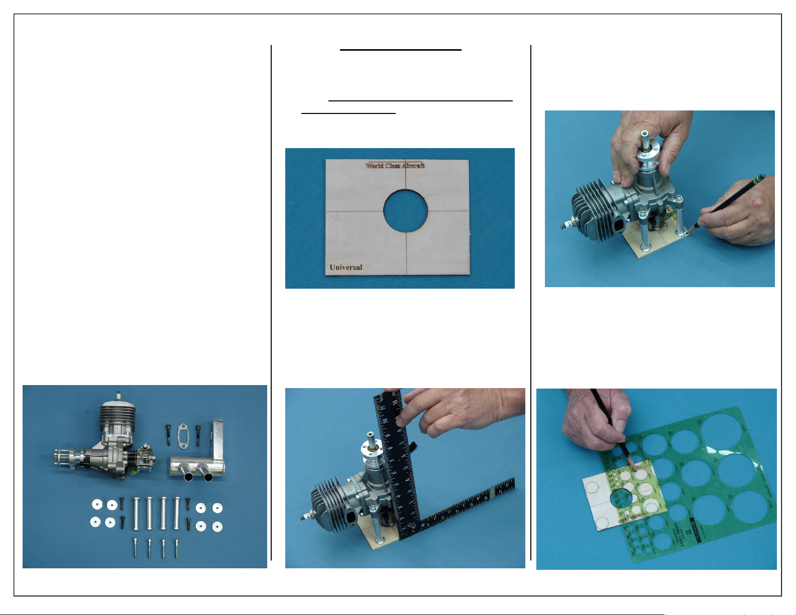
ENGINE INSTALLATION
1. The 30cc Bravata will accept a wide range of
engine types. The DLE 30 engine with J’tec
pitts muffler was used for the test flights. Gather
the following items needed for engine installation:
Required Parts
◊ 1 - Universal Mounting Template
Required Parts -Not Included
◊ 1 - 30cc Engine: DLE 30 Shown
◊ 4 - DLE 30 Standoffs w/ Mounting Bolts
◊ 8 - 1/2” Diameter Fender Washers
◊
Required Tools and Adhesives
◊ 1 - Pencil
◊ 1 - Masking Tape
◊ 1 - Electric Drill
◊ 1 - 3/16” Drill Bit
Universal Template:
2. If using a motor that is not a DLE 30 please follow these directions for using the universal template. If a DLE 30 is to be used, please skip to
step #1 On page #33
3. Place the engine on universal mounting template
as shown. Use a square to align the propeller
output shaft with the pre marked thrust lines on
the template.
4. Mark the location of the standoffs on the template as shown. Ensure that the motor does not
move during this step.
5. Use a stencil to fill in any missed parts where the
standoffs were marked in step 4.
32 Aeroworks 30cc Bravata Assembly Manual
Page 33
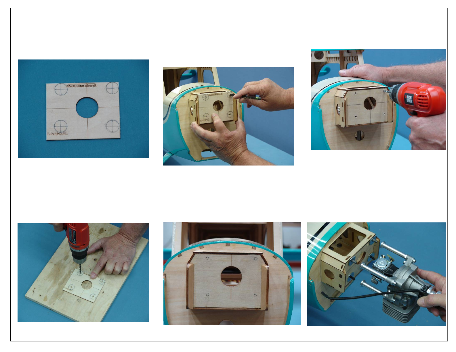
6. Mark the center of each standoff location as
shown.
7. Use a 3/16” drill bit to drill the four mounting
hole locations as shown below.
8. Align laser etched lines on template with lines
on firewall. Use a felt tip marker to mark the
location of the mounting holes.
9. Follow the remaining engine mounting steps for
mounting instructions.
DLE 30 Installation
1. The firewall has been pre marked for the DLE
30 gas engine.
2. Use a 3/16” drill bit to drill the engine mounting
holes in firewall.
3. Using mounting bolts and flat fender washers
mount engine to firewall.
4. Use blue loctite to secure the engine mounting
bolts in place. This will insure that the mounting
bolts stay in place over time.
Aeroworks 30cc Bravata Assembly Manual 33
Page 34
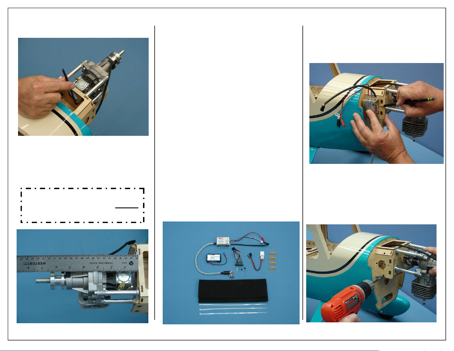
5. Tighten the bolts evenly to prevent crushing of
the firewall.
6. Distance from front of firewall to front of
engine prop hub is 6 3/8”.
Note: Use aluminum stand offs (supplied with
engine) and washers (not supplied) to achieve
correct distance.
Mounting Distance is: 6 3/8”
IGNITION
INSTALLATION
1. Gather the items shown below for ignition
installation.
Required Parts
◊ 2 - 8x80x300mm Foam Pad
◊ 3 - 8x450mm Nylon Ties
Required Parts -Not Included
◊ 1 - Ignition Module
◊ 1 - Battery (2600mah Li-Ion Shown )
◊ 1 - Ignition Regulator (Smart-Fly Shown )
◊ 1 - Ignition Switch (MPI Shown )
◊ 4 - Aeroworks Safety Clips
◊ 1 - Dubro Universal Kwik-Switch Mount
Part# 203
◊ 1 - Dubro Ball Link Sockets Part #188
Required Tools and Adhesives
◊ 1 - Pencil/felt tip pen
◊ 1 - Electric Drill
◊ 1 - 1/16” Drill Bit
◊ 1 - Wire Cutter
2. Position the ignition module on the side of the
engine mounting box and mark the location of
the nylon tie holes as shown.
3. Use a 1/4” bit to drill the ignition module
mounting holes.
34 Aeroworks 30cc Bravata Assembly Manual
Page 35
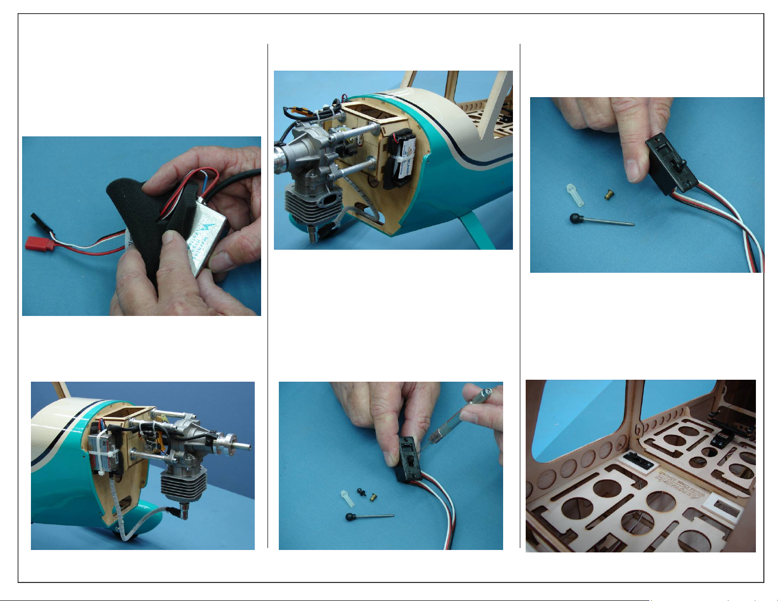
4. Thread nylon tie through mounting holes.
5. Roll the supplied foam rubber to make a 4 layer
pad as shown. Make the pad slightly larger than
the ignition module.
6. Secure ignition module with nylon tie as necessary.
7. Using a nylon tie, install the ignition battery as
shown.
8. Using a pin vice carefully drill into the sliding
portion of the switch as shown.
9. Install the threaded ball onto the sliding portion
of the switch.
10. Switch mounting holes have been cut into the
radio floor. Install your switch using the hardware supplied by the switch manufacturer.
Aeroworks 30cc Bravata Assembly Manual 35
Page 36
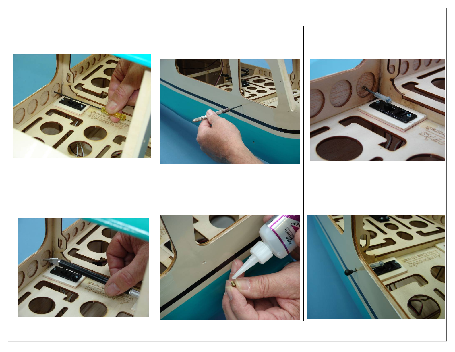
11. Use a ball driver to locate where the switch
pushrod will exit the fuse. Lightly mark the
wood in this area being careful not to push
through the fuse side.
13. Use a pin vice to drill through the fuse side as
shown.
15. Snap ball link socket onto ball and thread the
switch pushrod into the ball link.
12. Using a hobby knife, puncture the location
marked in the previous step. This will allow you
to drill from the outside.
36 Aeroworks 30cc Bravata Assembly Manual
14. Glue a brass servo eyelet into the hole. This will
keep the hole from widening over time.
16. Finished ignition switch installation show.
Page 37
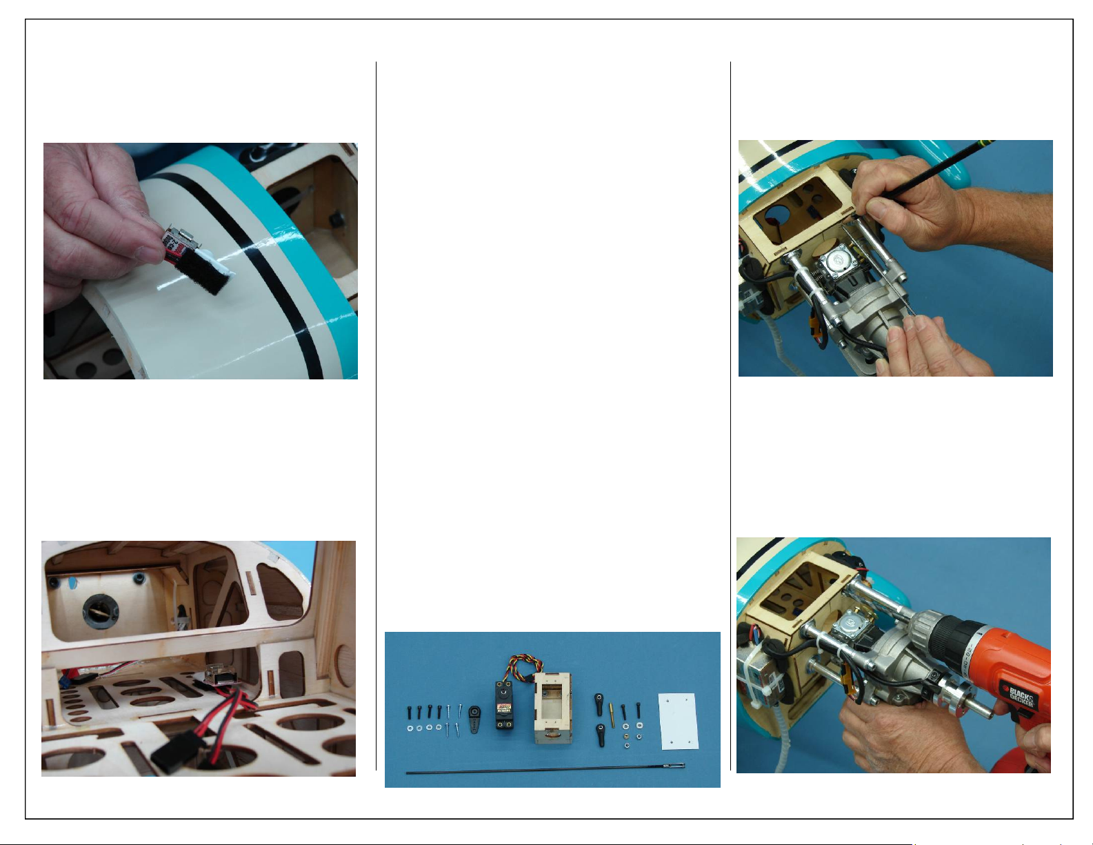
17. Using a small piece of hook and loop material,
secure the Smart-Fly ignition regulator to the
fuse floor.
18. Final ignition regulator installation shown below.
THROTTLE SERVO INSTALLATION
1. Gather the throttle and choke items as shown
below:
Required Parts
◊ 1 - Prebuilt Plywood Servo Mount
◊ 1 - 4-40x300mm Threaded Pushrod
◊ 1 - 4-40 Threaded Solder Coupler
◊ 2 - 4-40 Ball Links
◊ 2 - 4-40x16mm Hex Head Bolts
◊ 2 - 4-40 Lock Nuts
◊ 1 - Brass Spacer
◊ 1 - 3mm Flat Washer
◊ 1 - Servo Mount Template
◊ 4 - 4-40 Servo Mount Mounting Bolts
◊ 4 - 4-40 Flat Washers
Required Parts -Not Included
◊ 1 - Throttle Servo
◊ 4 - Servo Mounting Screws (Micro Fastener
Part number STW0209 recommended)
◊ 1 - 3/4” servo arm
Required Tools and Adhesives
◊ 1 - Pencil/felt tip pen
◊ 1 - Phillips Screw Driver
◊ 1 - 5/64” Ball Driver
◊ 1 - Electric Drill
◊ 1 - 1/16” Drill Bit
◊ 1 - 7/64” Drill Bit
◊ 1 - Rotary Cutting tool with Cutting Disk
◊ 1 - Wire Cutter
◊ 1 - Soldering Iron
◊ 1 - Silver Solder “Sta-Brite Recommended”
◊ 1 - 80 Grit Sandpaper
◊ 1 - .34oz Bottle Blue IC-Loc Thread Locker
2. Mark the location of the throttle pushrod on the
firewall as shown.
3. Use a drill bit to drill the holes for the throttle
pushrod.
Aeroworks 30cc Bravata Assembly Manual 37
Page 38
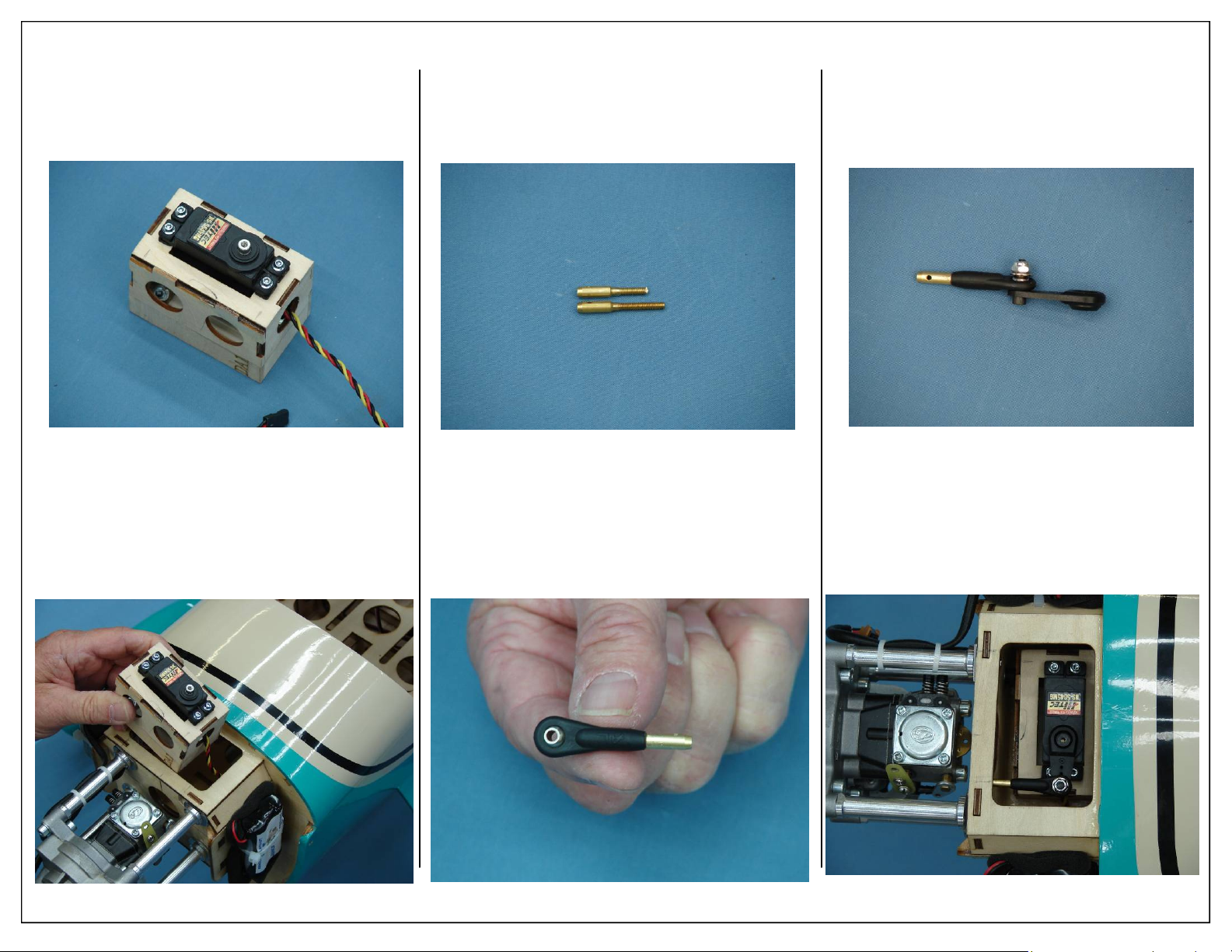
4. Install the throttle servo in the preassembled laser cut mounting tray as shown below.
6. It may be necessary to shorten the threaded portion of the solder coupler as shown.
8. Assemble brass threaded coupler to 4-40 ball
link and ball link and brass spacer to the servo
arm as shown below.
5. Place servo mounting tray inside motor box as
shown.
38 Aeroworks 30cc Bravata Assembly Manual
7. Thread ball link onto solder coupler as shown.
Ball link should touch the non-threaded portion
of the solder coupler.
9. Placer Servo arm on servo. The servo arm
should be parallel with the servo case.
Page 39
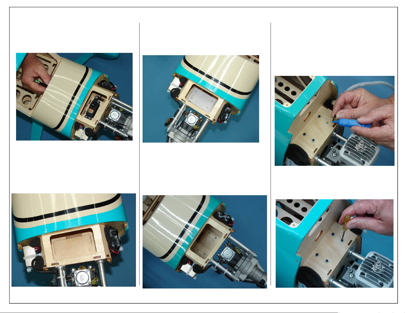
10. Mark the location of the throttle servo mount as
shown. It may be necessary to go in through the
cabin area to fully mark throttle servo mount.
12. Place servo mounting template in motor box and
align with marks made in the previous steps.
13. Mark mounting holes onto motor box floor.
15. Place the 4-40 mounting bolt and flat washer
through the mounting holes as shown. Mounting
bolts will pass through the motor box with the
heads accessible from the outside of motor box.
Note: Use blue loctite on mounting bolts.
11. Finished throttle servo mount mark shown below.
Aeroworks 30cc Bravata Assembly Manual 39
14. Drill all four mounting holes as shown. Use caution when drilling, drilling to fast may cause plywood to splinter around mounting hole.
16. Place servo mount inside fuse and align with
mounting bolts. Tighten mounting bolts at this
time.
Page 40
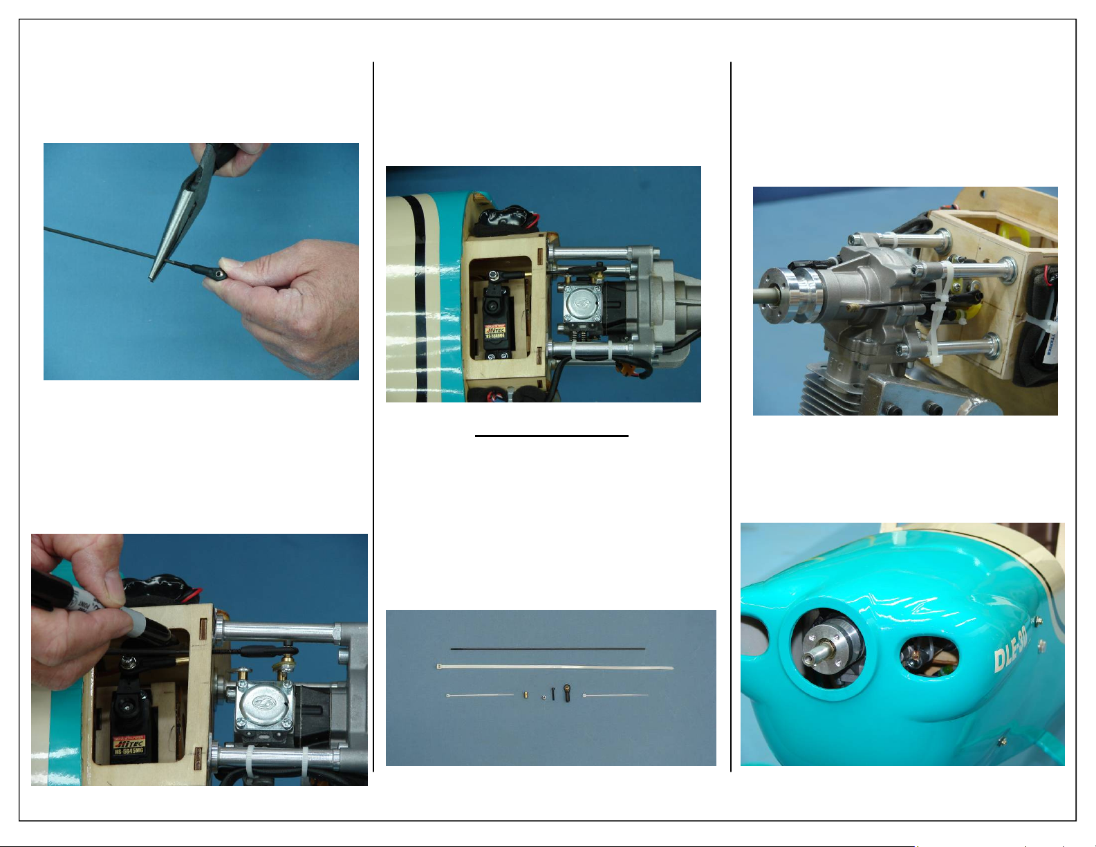
17. Assemble ball link to threaded end of pushrod.
Note: Thread ball link half way onto pushrod to
allow for proper adjustment during final
installation.
18. Attach throttle pushrod to the carburetor throttle
arm with the 4/40 ball link
19. With servo arm still parallel to servo and throttle
arm of carburetor in the center or half throttle
position. Mark the cut location for the throttle
push rod.
20. Solder throttle pushrod to brass coupler.
21. Attach the throttle pushrod with the 4/40 ball
links and secure. Power up the receiver and
throttle servo and adjust pushrod for proper operation. Ensure the servo or rod does not bind or
jam at closed or full open positions.
Choke Installation
1. Choke installation items shown below, items are
not included.
◊ 1 - 4-40 metal rod threaded at one end
◊ 1 - 4-40 ball link assembly with hardware
◊ 1 - 4-40 Threaded insert
◊ 1 - Large Zip Tie
◊ 2 - Small Zip Ties
2. We recommend installing the carburetor choke
pushrod as shown. Use nylon ties to provide
support and holding friction for the choke pushrod. Place silicon fuel tubing over the wire
pushrod to prevent damage from vibration and
provide holding friction. Solder a threaded insert on the end of the pushrod to provide a finger
grip.
3. Location of manual choke pushrod shown below.
40 Aeroworks 30cc Bravata Assembly Manual
Page 41
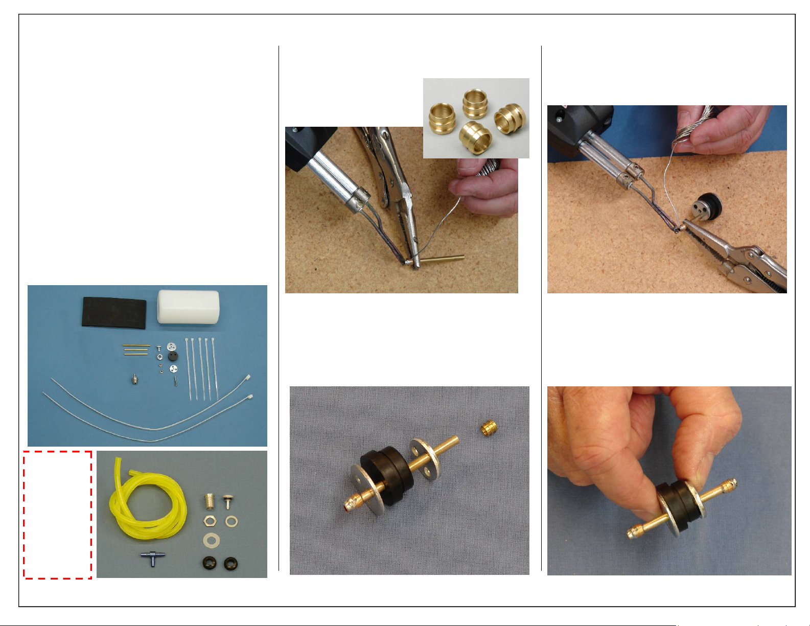
FUEL TANK AS SEMBLEY
1. Gather the fuel tank parts as shown below.
Required Parts
◊ 1 - 450cc (15oz) Gas Tank
◊ 1 - Rubber Stoppers (Universal)
◊ 3 - Brass Tubes
◊ 1 - Aluminum Stopper Front Plates
◊ 1 - Aluminum Stopper Back Plates
◊ 1 - Phillips head bolts
◊ 2 - Brass Barbs for Fuel Line
Required Parts -Not Included
◊ 1 - Aeroworks Fuel Line Installation Kit
Required Tools and Adhesives
◊ Pencil/felt tip pen
◊ Phillips Screw Driver
◊ Wire Cutter
◊ Soldering Iron
◊ Silver Solder “Sta-Brite Recommended”
◊ 80 Grit Sandpaper
2. Locate the (2) supplied brass fuel barbs. Solder a
brass fuel barb to the fuel line pick up tube. This
will keep the weight of the fuel clunk from pulling the fuel line off the brass tube.
Note: No brass barbs are
required for the air
vent lines.
4. Solder a brass fuel barb to the other end of the
fuel pick up line.
3. Assemble the fuel pick up line, rubber stopper
and metal end caps. As shown below.
5. Final assembly of rubber fuel stopper with fuel
pick up tube shown below.
Fuel Line
Installation
kit available
separately
from
Aeroworks
Aeroworks 30cc Bravata Assembly Manual 41
Page 42
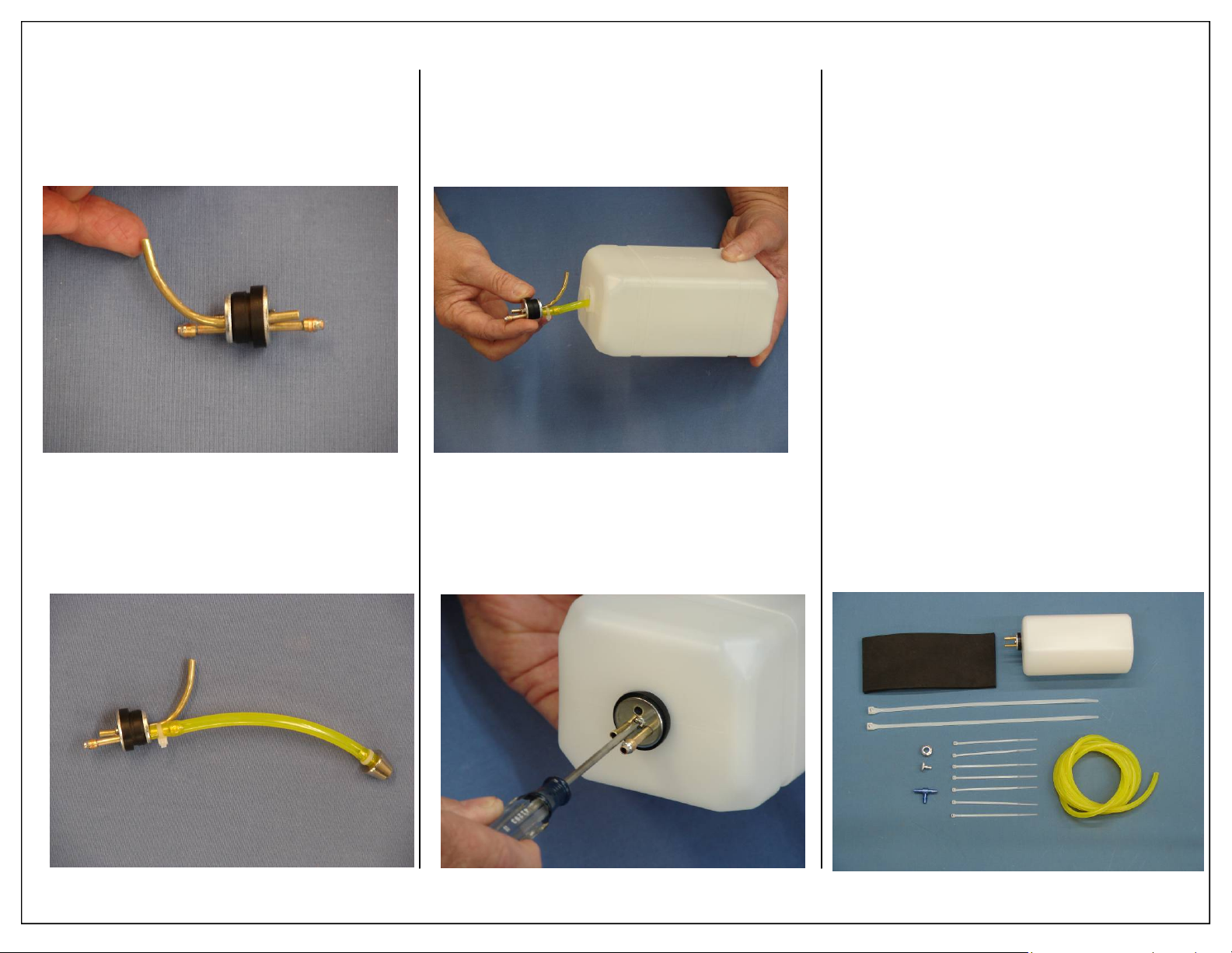
6. Install air vent tube into rubber stopper and bend
upward.
Note: No brass barbs are required for the air vent
tube.
8. Insert the rubber stopper assembly into the tank
with the vent tube at the top of the tank.
FUEL TANK INST ALLATION
1. Gather the fuel tank parts as shown below.
Required Parts
◊ 1 - 450cc (15oz) Gas Tank Assembled
◊ 1 - 6 x 130 x 70mm Foam Sheet
◊ 2 - 8 x 450mm Nylon Ties
◊ 7 - 3 x 150mm Nylon Ties
Required Parts -Not Included
◊ 1 - Aeroworks Fuel Line Installation Kit
Required Tools and Adhesives
◊ Pliers
◊ Wire Cutter
◊ Electric Drill
◊ Various Drill Bits for Fuel Dot Installation
◊ 1oz Bottle Gap Filling CA Glue
7. Install the fuel tubing and clunk. Secure the fuel
tubing with nylon ties to the pick-up tube and
clunk.
9. Secure the rubber stopper with set screw. Take
care not to strip threads by over tightening set
screw.
42 Aeroworks 30cc Bravata Assembly Manual
Page 43
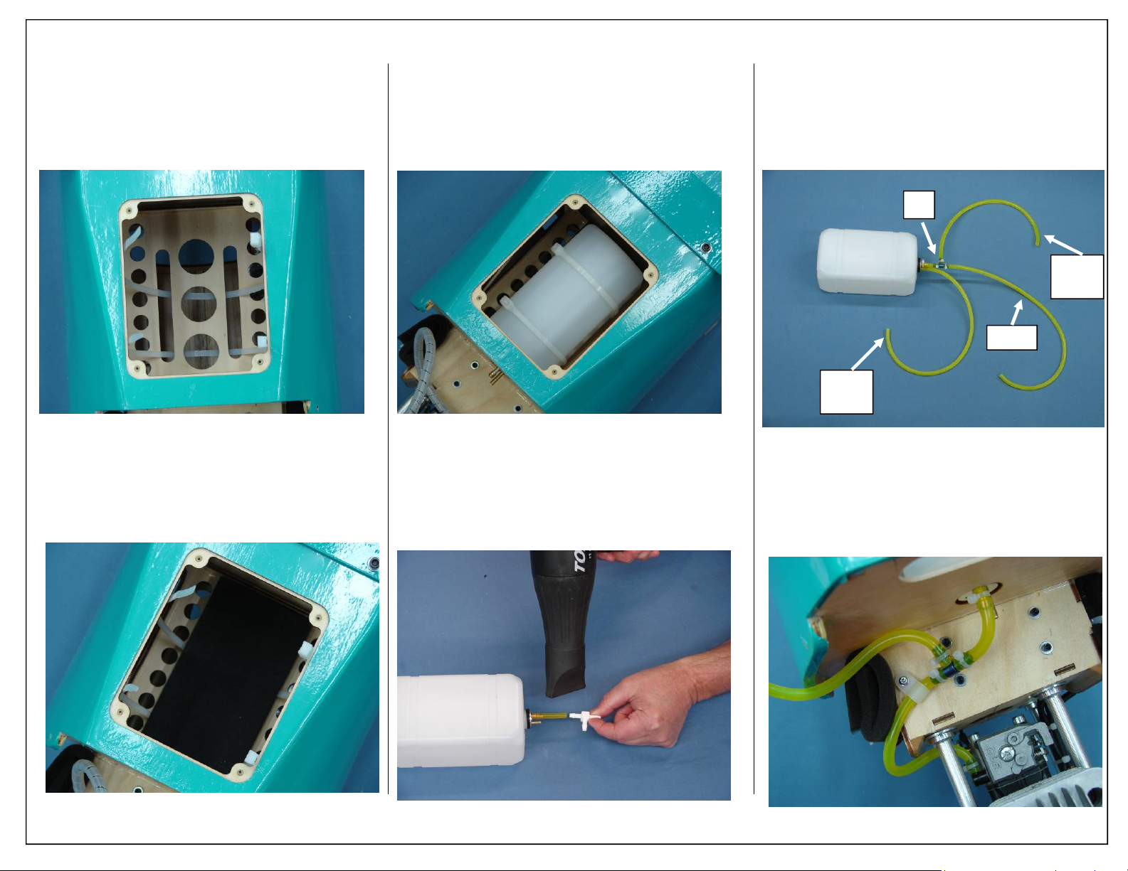
2. Thread nylon ties under tank mounting plate and
center in position.
3. Install foam rubber pad for fuel tank to rest on.
Foam rubber will help prevent fuel from foaming or getting air bubbles from engine vibration
4. Tighten nylon ties to secure tank in place.
5. Use wire cutter to remove excess nylon tie after
tightening.
6. Install a short piece of fuel line and the fuel “T”
to the fuel pick up tube.
Note: Using a heat gun to soften the fuel line will
help with the installation of the fuel “T”.
7. Install the fuel pick up and fuel filler lines to the
fuel tank.
Note: It is recommended you always use a fuel
filter on your gas can, filters should not be
installed inside the airplane. Inline fuel filter
can clog and cause your engine to quite.
T
Fill
Line
Carb
Vent
Line
8. Use small nylon ties to secure fuel line.
Note: Gasoline will cause the fuel line to expand
over time. Always secure fuel lines with
nylon ties to prevent them from pulling off
during flight.
Aeroworks 30cc Bravata Assembly Manual 43
Page 44
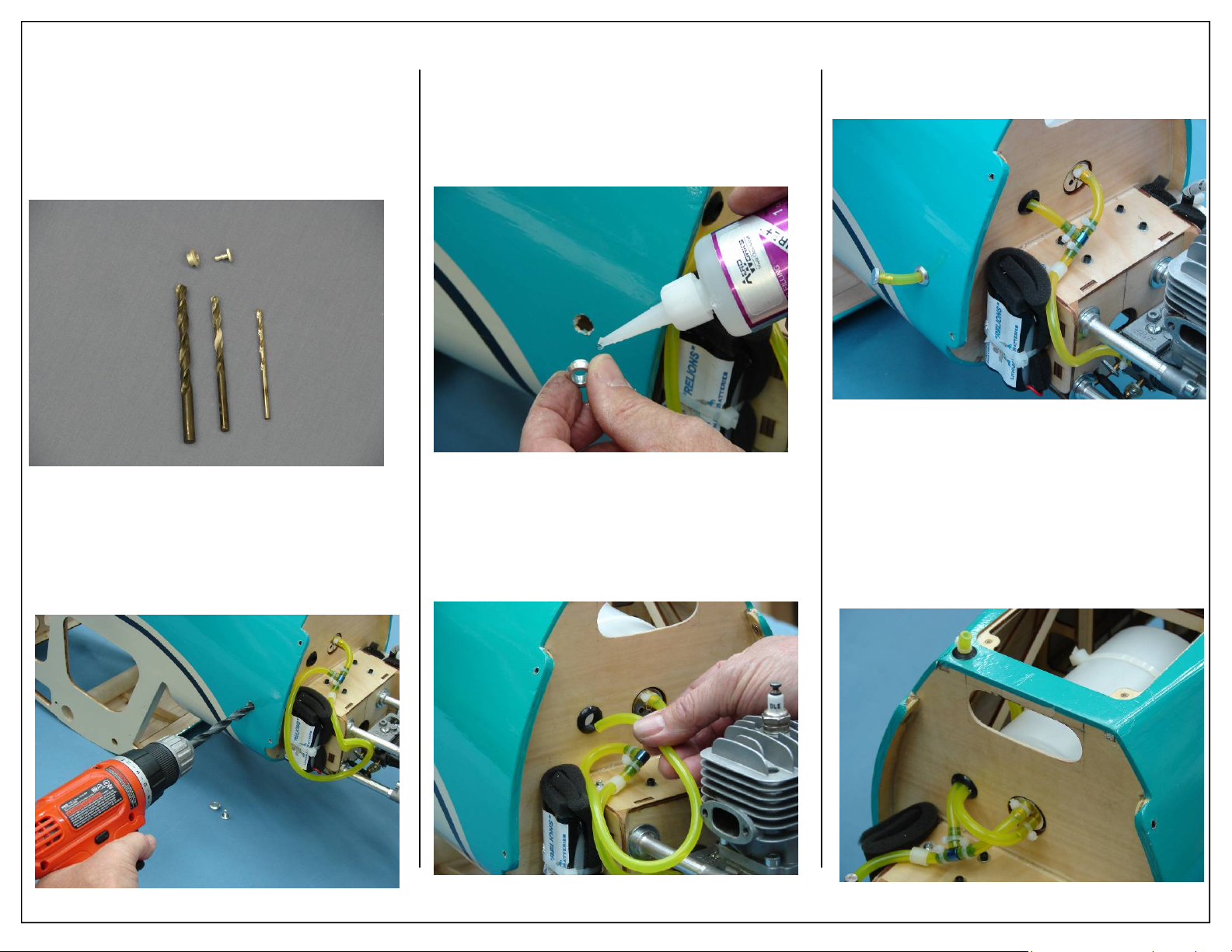
9. Gather the fuel filler dot and drill bits as shown
below.
Note: We recommend you start with a smaller size
drill bit then increase the bit size to the
correct size to fit your filler dot. This will
help prevent the fuse side from splitting
or cracking.
10. Mark location of fuel filler dot.
11. Drill hole to accommodate fuel filler dot.
12. Use thick CA to secure fuel dot in fuse.
13. Drill a hole in the front fuse former and install a
large grommet as shown. Pass filler line through
grommet and into fuse.
14. Feed filler line through dot and plug line into
filler plug as shown.
15. Feed vent line tubing through bottom of fuse.
Cut off excess fuel line.
Note: Place a zip tie around the vent line as shown.
Be careful not to tighten the zip tie to the
point of closing the vent line. This will pre vent the vent line from falling back inside
the fuse and flooding the airplane with gas
during fueling.
44 Aeroworks 30cc Bravata Assembly Manual
Page 45
FUSELAGE BOTTOM HATCH
INSTALLATION
1. Gather the Fuse Bottom Hatch items as shown
below.
Required Parts
◊ 1 - Fuse Bottom Hatch w/Air Vent
◊ 1 - Fuse Bottom Hatch w/o Air Vent
◊ 4 - Phillips head mounting screws
Required Tools and Adhesives
◊ Phillips head screw driver
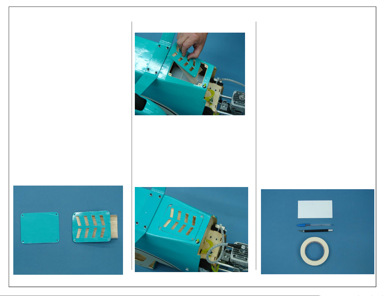
2. Two different fuse bottom hatches have been
included with the 30cc Bravata. If using a single
cylinder motor that is mounted inverted it is
highly recommended that the air exit hatch be
used. This hatch has been designed to remove
hot air from inside the cowling while also keeping it out of the fuselage. An inlet hole has already been cut in the fuse former to allow air to
pass into the air exit hatch.
3. If a different motor option is used, a solid hatch
has been provided.
4. Place hatch into pre cut mounting location as
shown. Make sure that the air scoop correctly
align with the air inlet in the fuse former.
5. Secure hatch with four Phillips head mounting
screws as shown.
Note: Aeroworks has found this method to provide
sufficient cooling for the DLE 30 gas engine.
It is still important to check motor
temperatures to ensure it is not running too
hot. If your engine does run hotter than the
manufacturer suggest, cooling hole may need
to be made in the cowling.
COWLING INSTALLATION
1. Gather the following items for the cowling installation.
Required Parts
◊ 1 - 30CC Bravata Cowling
◊ 1 - 3 x 6” Card Stock for Muffler Template
Required Tools and Adhesives
◊ 1 - Felt tip pen
◊ 1 - Masking Tape
◊ 1 - Rotary Cutting tool with Cutting Disk
Aeroworks 30cc Bravata Assembly Manual 45
Page 46
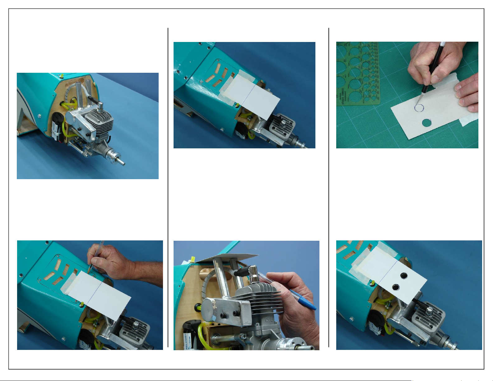
2. Temporarily install wrap around pitts muffler to
engine as shown.
4. Fully tape card stock to fuse to prevent it from
shifting while marking muffler exit location.
6. Remove template from fuse and using a hobby
knife to remove card stock from marked areas of
template.
3. Tape card stock to bottom of fuse and mark its
location. This will ensure the template is placed
in the exact spot when marking the cowl.
5. Mark the location of the individual exhaust exits
as shown.
7. Place template back on fuse aligning with marks
made in a previous step.
8. Check the fit of the template at this time. It may
be necessary to make small adjustments to the
cutout to get it to fit properly.
46 Aeroworks 30cc Bravata Assembly Manual
Page 47
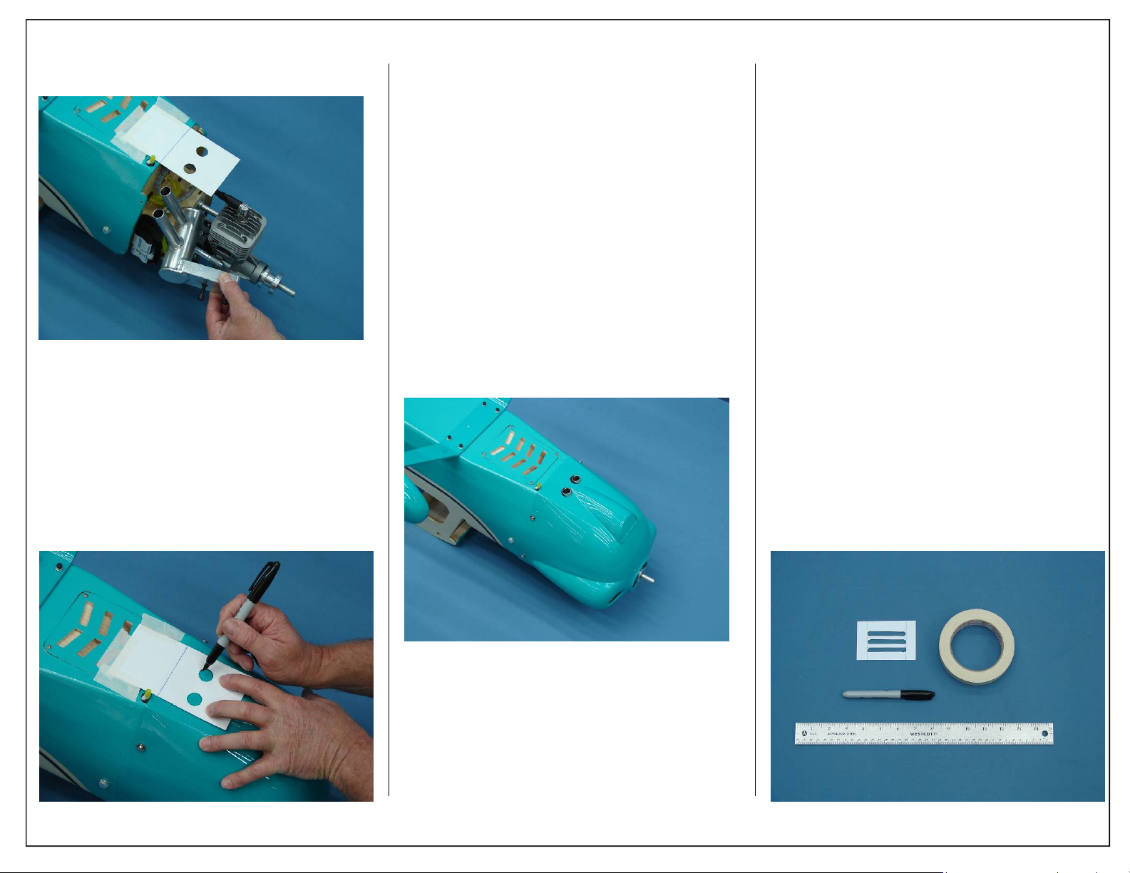
9. Remove pitts muffler from engine at this time.
Use caution not to disturb the template.
10. Align template with bottom of cowl. Use a felt
tip marker to transfer the template cutout pattern
to the cowl and mark cut location.
Note: Pay close attention to the marker you
choose. Some permanent markers may not
be easily removed. Also, When using
rubbing alcohols or other paint removers,
always test on painted parts before using!
11. Remove the template and use a rotary cutting
tool and sanding drum to cut out the openings in
the cowl.
Note: Take care not to cut or scratch the
cowl.
12. Reinstall muffler using the supplied gasket or
high temp silicon gasket material and securely
bolt to cylinder head.
1. Gather the following items to cut the front air
inlet.
Required Parts
◊ 1 - 30CC Bravata Cowling
◊ 1 - Front Air Inlet Template
◊ 4 - 4-40 Cowl Mounting Bolts
◊ 4 - #6 Bonded Washers
Required Tools and Adhesives
◊ Felt tip pen
◊ Masking Tape
◊ Rotary Cutting tool with Cutting Disk
◊ Ruler
◊ 5/64” Ball Driver
2. Front air inlet has been designed for inverted
motor installation. If using a different motor
installation these inlet holes are not required.
3. Ensure front air inlet aligns with engine head.
This will allow maximum airflow over the cooling fins of the engine.
Aeroworks 30cc Bravata Assembly Manual 47
Page 48
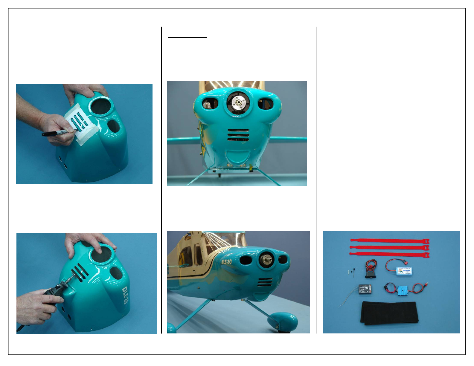
4. Align template with front of cowl. Use a felt tip
marker to transfer the template cutout pattern to
the cowl and mark cut location.
Note: Pay close attention to the marker you
choose. Some permanent markers may not
be easily removed. Also, When using
rubbing alcohols or other paint removers,
always test on painted parts before using!
5. Remove the template and use a rotary cutting
tool and sanding drum to cut out the openings in
the cowl.
Note: Take care not to cut or scratch the
cowl.
6. Finished front air inlet cutout shown below.
Builders Tip:
A round dowel wrapped with 120 grit
sandpaper can be used to clean up
cutouts. This will ensure all 3 cutouts
are the same size and have the same
radius.
7. Mount cowl to the fuse using
(4) 4-40x16mm button style hex head bolts
(4)#6 bonded washers
RADIO INSTALLATION
1. Gather the radio installation items as shown below.
Required Parts
◊ 2 - 8x80x300mm Foam Pad
◊ 3 - 356x12.5mm Velcro Straps
Required Parts -Not Included
◊ 1 - Receiver 6-8 channel recommended
◊ 1 - Batteries (2600mah Li-Ion Shown )
◊ 1 - Regulators (Fromeco Sahara Shown )
◊ 1 - Receiver Switch (Smart-Fly Shown )
◊ 4 - 18” Servo Extensions
◊ 1 - Dubro Universal Kwik-Switch Mount
Part# 203
◊ 1 - Dubro Ball Link Sockets Part #188
◊ 1 - Adhesive backed Velcro
◊ 4 - Small Nylon Ties
Required Tools and Adhesives
◊ Pencil/felt tip pen
◊ Electric Drill
◊ 1/16” Drill Bit
◊ Wire Cutter
◊ Masking Tape
48 Aeroworks 30cc Bravata Assembly Manual
Page 49
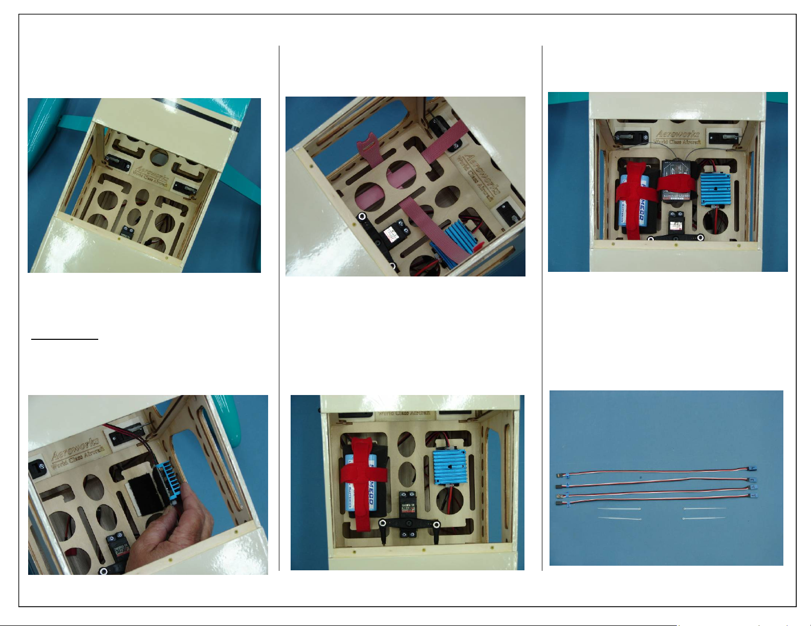
2. Install receiver switch using same steps outlined
for ignition switch installation.
Note: Ignition switch installation shown on pages 35
and 36 Steps 8-16
4. Slide 2 One Wrap Straps under radio tray as
shown.
6. Mount the receiver using the same method as
used for battery mounting.
3. Attach hook and loop material to the backside of
the regulator as shown. Secure regulator to fuse
floor.
Builders Tip: Placing thick CA on adhesive side of
hook and loop material will allow it to
adhere firmly to the plywood radio
floor.
5. Install battery using foam padding and securely
tighten one wrap straps as shown.
7. Gather four 18” Servo extensions and small nylon ties as shown. This will be used to connect
the ailerons and flaps to the receiver.
Aeroworks 30cc Bravata Assembly Manual 49
Page 50
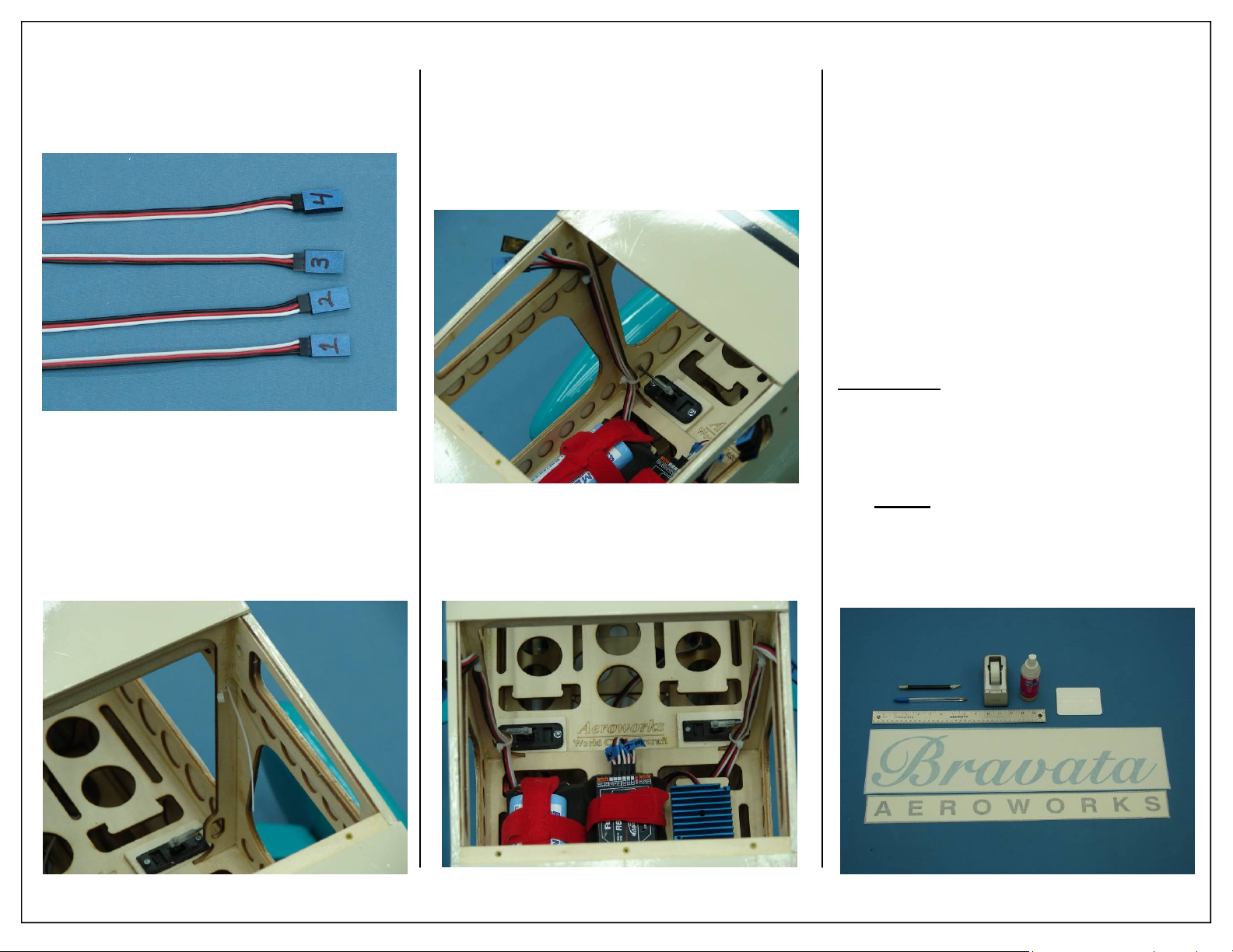
8. Label the four extensions 1-4 as shown. Repeat
this step for the aileron and flap connectors coming out of the wing. This will allow the extensions to be plugged into the correct channels
during field assembly.
9. Drill 2 small holes through fuse former as shown
below.
10. Pass small nylon tie through holes in fuse former. These will secure the extensions and help
keep them away from the windows.
11. Route 2 extensions up the fuse former and out
the access hole in the side of the fuse. Tighten
nylon ties and remove excess with wire cutters.
12. Repeat for remaining 2 extensions on opposite
side of fuse.
13. Finished receiver installation shown below.
DECAL INSTALLATION
1. Gather the DECAL installation items as shown
below.
Required Parts
◊ 1 - Vinyl Decal Set
◊ 1 - Large Transfer Tape
Required Tools and Adhesives
◊ Ball Point Pen
◊ Hobby Knife
◊ Ruler
◊ Scotch Tape
◊ Rapid Tac Decal Application Fluid
◊ Plastic Squeegee
Builders Tip:
before any decals are applied.
Note: Only one piece of transfer tape has been
supplied. This transfer tape must be applied to
decal and then reused for the next decal.
Do Not
transfer tape.
Clean surface and tighten all covering
attempt to install decal with out
50 Aeroworks 30cc Bravata Assembly Manual
Page 51
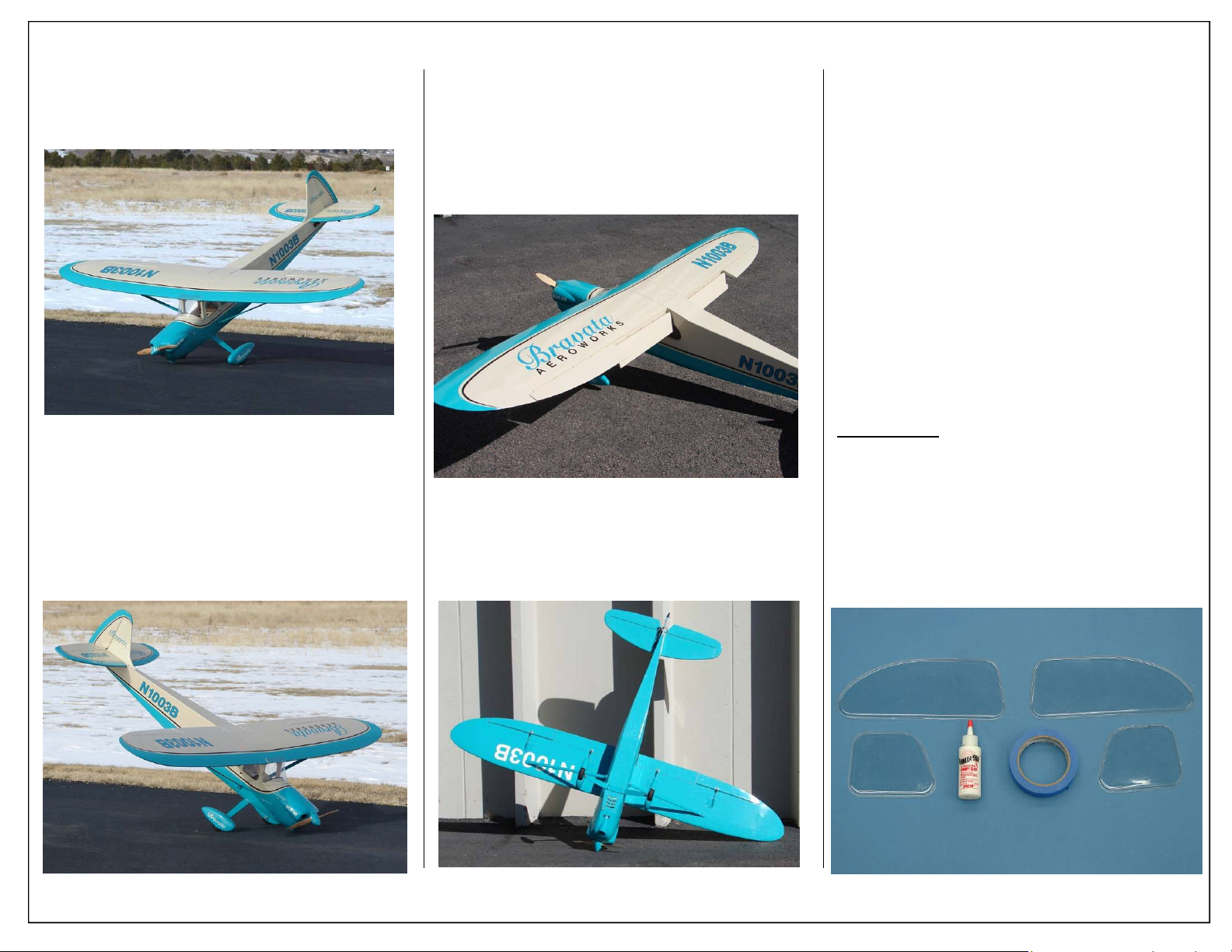
2. Placement of included decals shown below.
3. Placement of included decals shown below.
4. Placement of included decals shown below.
5. Placement of included decals shown below.
SIDE WINDOW AND
WINDSHIELD INSTALLATION
1. Gather the window installation items as shown
below.
Required Parts
◊ 1 - Front Windshield -(Not Shown)
◊ 6 - Phillips Head Mounting Screws
◊ 2- Front Side Windows (Left & Right Set)
◊ 2 - Rear Side Windows (Left & Right Set)
Required Parts- Not Included
◊ 1 - Custom Dash Panel
Required Tools and Adhesives
◊ Masking Tape
◊ Canopy Glue
◊ Phillips Head Screw Driver
Builders Tip:
before installing.
Clean windows from both sides
Aeroworks 30cc Bravata Assembly Manual 51
Page 52
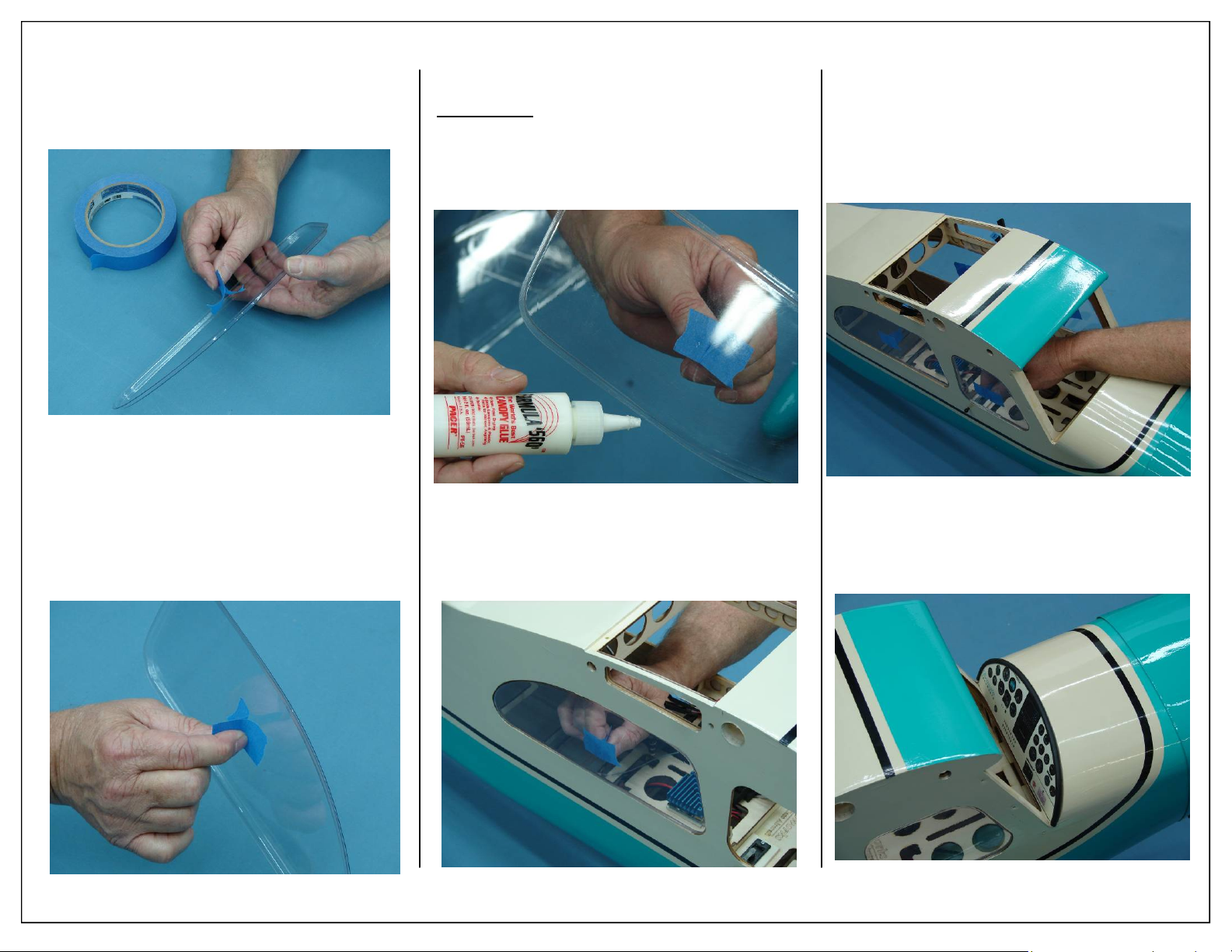
2. Make a small handle using masking tape by
folding masking tape over itself as shown.
3. Stick masking tape handle to inside of window
as shown. This will allow the window to be
placed in the fuse cut out without smearing canopy glue.
4. Apply a small amount of canopy glue to the window mounting rail as shown.
Builders tip:
rail with 80 grit sandpaper will help
the glue adhere to window. Use
caution to not scratch the visible
portion of window if this is done.
5. Place window in fuse cutout from inside fuse
cabin as shown. Allow glue to full cure before
removing masking tape.
Lightly scuffing the window mounting
6. Repeat previous steps for all remaining side windows.
7. Install optional dash panel at this time. Small
wood screws and double sided tape are recommended to secure dash panel.
52 Aeroworks 30cc Bravata Assembly Manual
Page 53
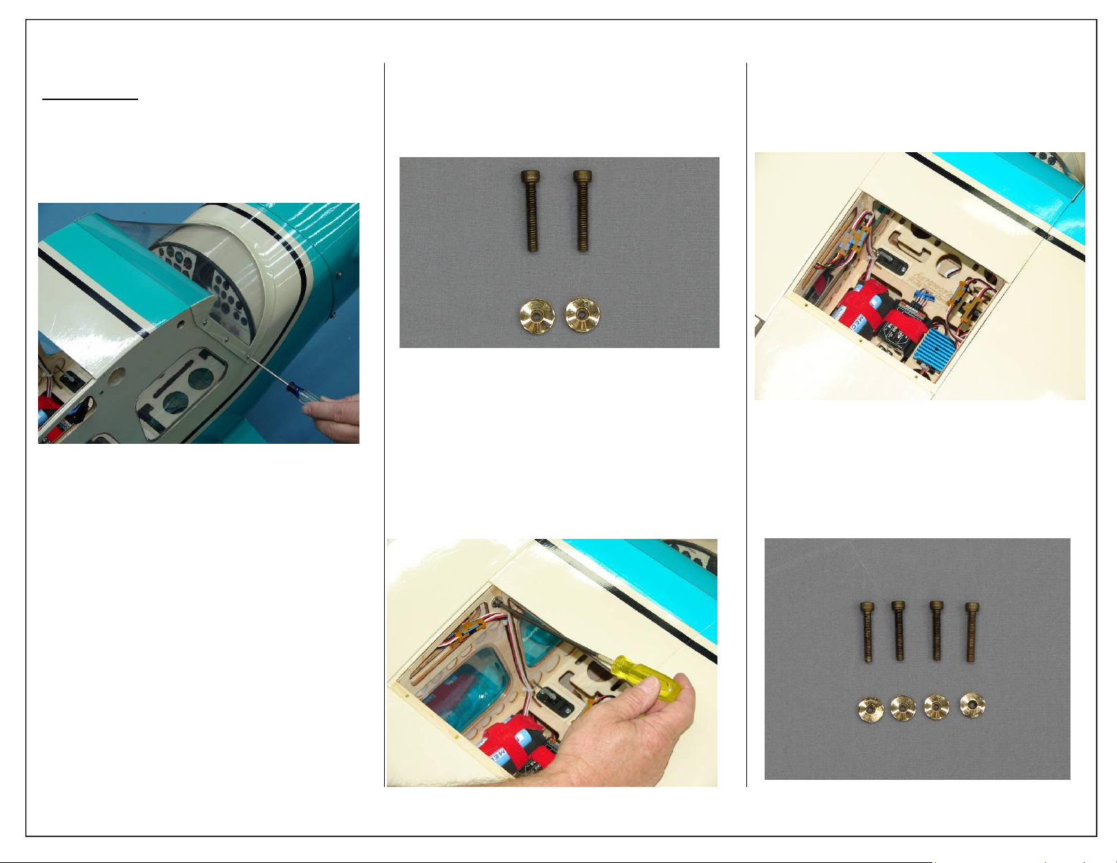
2. Reinstall front windshield using Phillips head
screws at this time.
Builders Tip:
applied to the mounting screw to
prevent the windshield from cracking
over time.
A small amount of silicone can be
PREFLIGHT
1. Gather (2) 8-32 wing mounting bolts and (2) #8
rubber backed washers for preparation of mounting the wings.
2. Slide the wing tube in the fuse wing tube sleeve.
Slide the wings on the wing tube and plug in the
aileron servo connectors. Slide the rubber
backed washers on the wing mounting bolts and
insert bolts through the fuse side and into the
wing root blind nuts. Tighten snugly but do not
over tighten and crack the fuse or wing root
wood.
3. Attach the 18” extension to the servo lead and
secure with Aeroworks Safety Clip. Ensure the
connectors will not come apart from vibration or
light tension.
4. Gather (4) 6-32 strut mounting bolts and (4) #6
rubber backed washers for preparation of mounting the struts.
Aeroworks 30cc Bravata Assembly Manual 53
Page 54
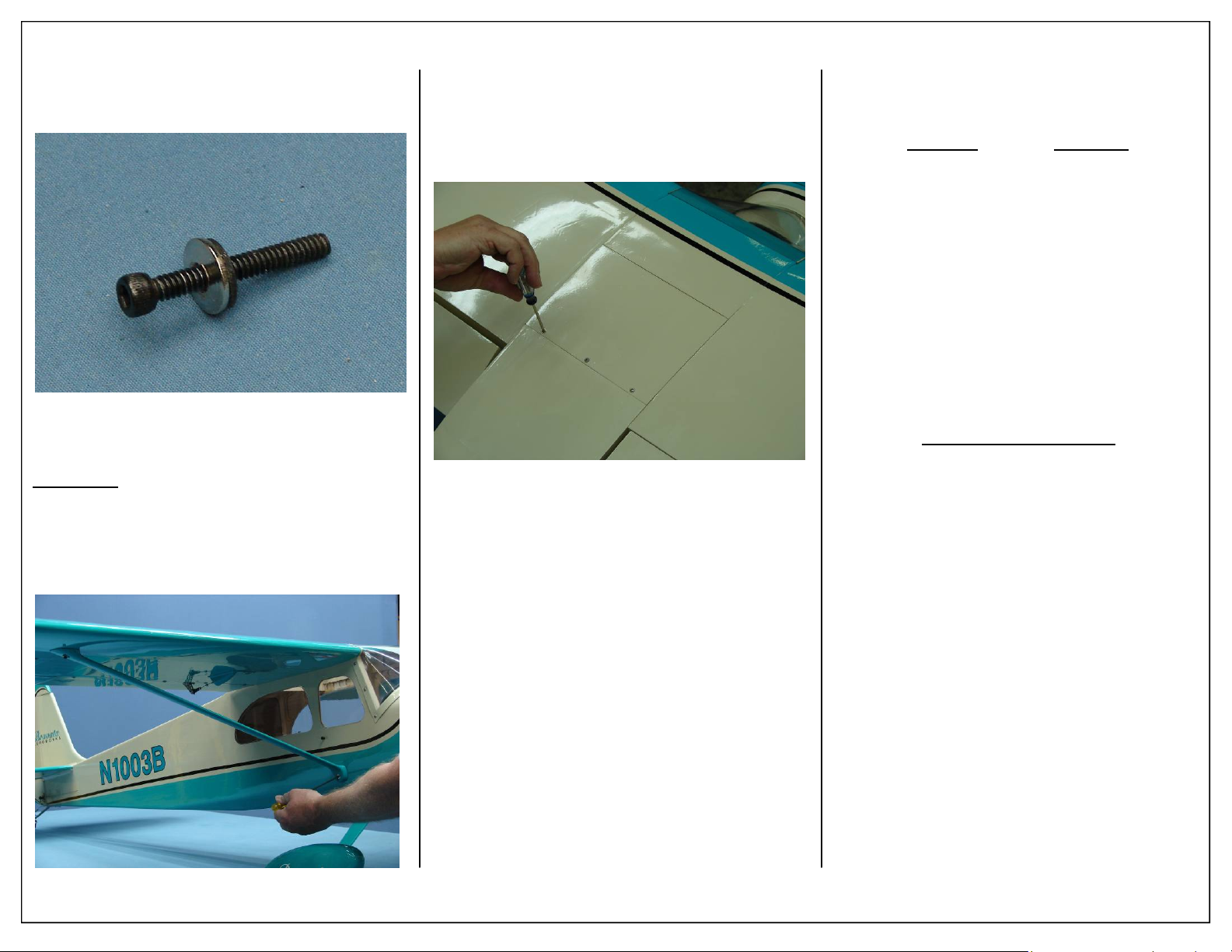
5. Slide the #6 Rubber backed washer onto the strut
mounting bolts as shown.
6. Secure struts to wing and then to fuse as shown.
Ensure both mounting bolts are fully tightened.
Important:
be used at all times. Failure to do so may
result in a catastrophic failure of the
wing.
Wing Struts are not optional and must
7. Secure fuse access hatch with (3) Phillips head
screws as shown.
CONTROL THROW
DEFLECTION TABLE
Low Rate
Aileron 1” or 15˚ up 2 1/2” or 35˚ up
1” or 15˚ down 2 1/2” or 35˚ down
Rudder 15˚ left 28˚left
15˚ right 28˚right
Elevator 3/4” or 12˚ up 1 1/2 ” or 25˚ up
3/4” or 12˚ down 1 1/2” or 25˚ down
Flap 1 1 2” or 25˚ down 2 1/2” or 40˚ down
Recommend Expediential:
25% expediential on low rates
40% expediential on high rates
Use the given rates as a starting point. Then
adjust rates from there to suit your own flying
style.
High Rate
54 Aeroworks 30cc Bravata Assembly Manual
Page 55
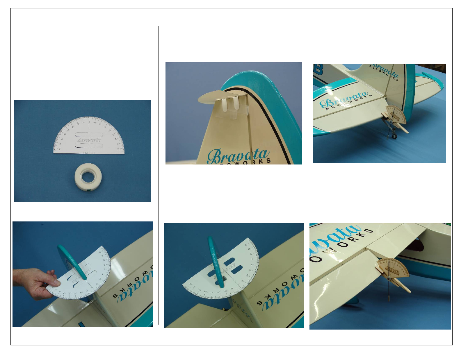
MEASURING CONTROL
THROWS
1. Gather the Rudder Throw Meter (Supplied) and
scotch tape.
3. Secure the tabs to the fin using scotch tape.
4. Degrees are measured at the tip of the boost tab
as shown below.
5. Elevator throw measured in degrees. Locate
throw meter at widest point of the elevator.
6. Aileron throw measured in degrees at widest
point of the aileron.
2. Slide the throw meter under the rudder boost tab.
Aeroworks 30cc Bravata Assembly Manual 55
Page 56
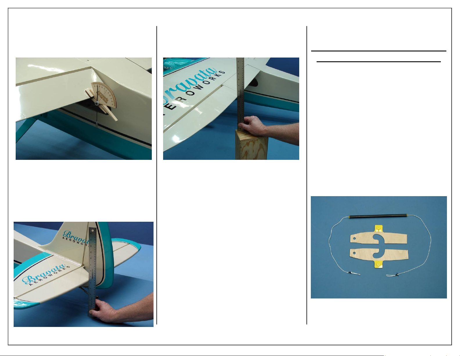
7. Flap throw measured in degrees at widest point
of the flap.
8. Elevator throw measured in inches at the widest
point of the elevator
9. Aileron throw measured in inches at the widest
point of the aileron.
CHECKING C.G. USING C.G.
BUDDY
C.G. Is 5 7/8” Back from the Wing
L.E. Measured at the Fuse Side
1. Aeroworks has included the new CG Buddy
with the 30cc Bravata . This handy tool will allow the builder to balance the airplane without
the need for an assistant.
2. Gather the CG buddy as shown below:
56 Aeroworks 30cc Bravata Assembly Manual
Page 57
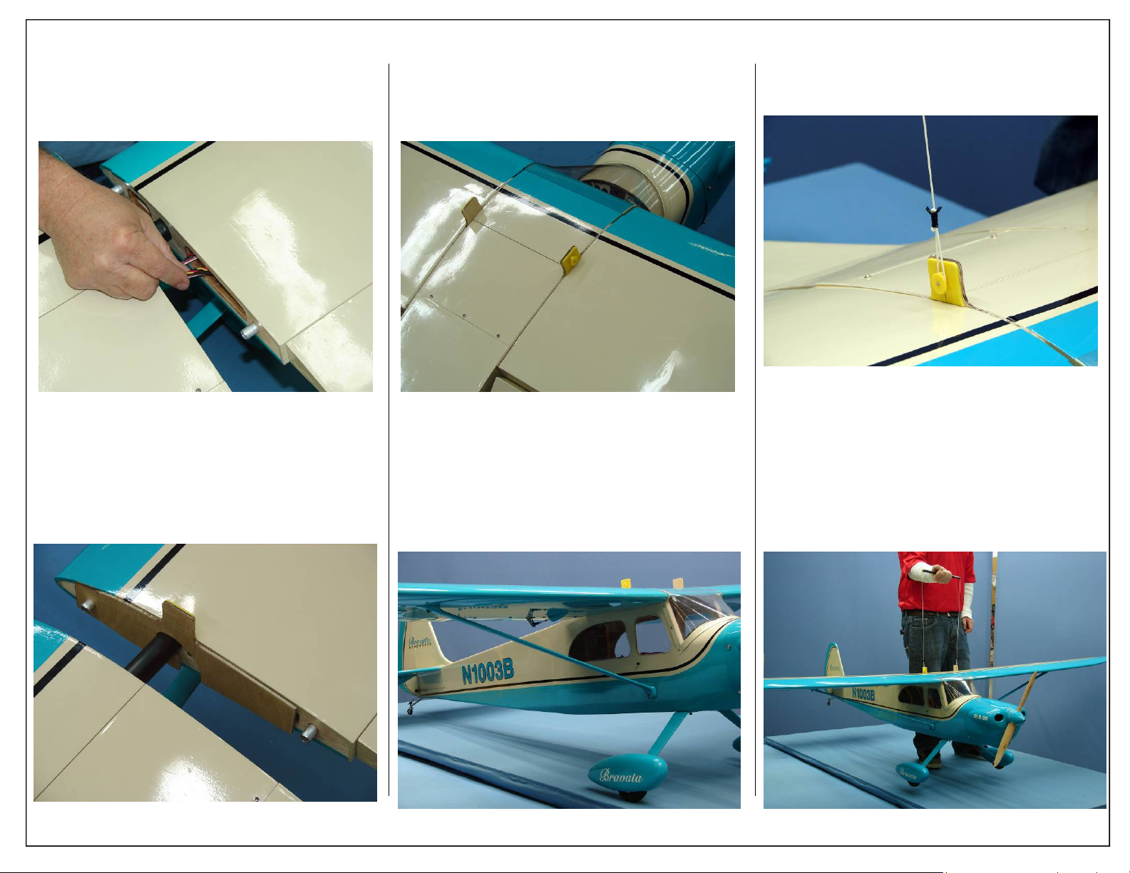
3. Tuck aileron and flap servo extensions inside
wing. This will allow the C.G. Buddy to sit flush
against the wing and fuse.
5. Slide wing back against the fuse as shown below.
6. Install CG Buddy on the opposite wing using the
same methods described above.
8. Attach loop to cable attachment as shown below.
4. Slide wings away from fuse and install the CG
Buddy on the wing tube and front rotation dowel
as shown. The cable attachment should be on the
top side of the wing. Make sure the CG Buddy is
securely latched to the wing tube and dowel before moving further.
7. Wing struts must be installed when checking
C.G. measuring C.G with struts not installed will
effect C.G. Location.
9. Lift airplane from center handle as shown, plane
should sit level when lifted. Balance the Bravata
without fuel in the tank with the batteries installed and READY TO FLY. Try to balance the
model by moving the batteries and receiver before adding any ballast.
Aeroworks 30cc Bravata Assembly Manual 57
Page 58

FLYING THE 30CC BRAVATA
The 30cc Bravata has been designed to be a
forgiving high wing sport airplane that can provide
big thrills for even the most seasoned pilot. Capable
of slow inverted and upright flight, large loops ,
knife edge flight, rolls and any combination of point
rolls, the 30cc Bravata is sure to impress anyone
who fly's it.
First Flights:
The first few flights should be performed on
low rates until you are comfortable with the airplane.
Takeoff is as easy as slowly applying power until the
airplane reaches take off speed, allow the tail wheel
to rise off the ground before pulling the airplane into
the air.
Once airborne, fly the 30cc Bravata around the
pattern a few times, getting used to its low and high
speed handling characteristics. You will see that the
30cc Bravata has a very soft stall that can only be
induced at low speeds, when stall speed is achieved
the airplane will drop the nose and attempt to keep
flying. By utilizing flaps this stall speed can be reduced even further, we found that using 25˚ of flaps
will give the best overall performance. The use of a
flap to elevator mix is recommended to reduce any
pitching when the flaps are deployed. Use a small
amount of down elevator mixed with the flaps to
really enjoy all that the flaps have to offer.
After you have become comfortable with the
plane, switch to high rates and really explore the
30cc Bravata’s full aerobatic potential. Weather flying large figures eights just inches from the ground
or performing a slow high angle knife edge pass the
Bravata feels very comfortable. The large wings do
cause the airplane to roll slower than most aerobatic
airplanes so be sure to give yourself plenty of altitude before attempting rolling maneuvers at first.
58 Aeroworks 30cc Bravata Assembly Manual
Landing the 30cc Bravata is very simple, so
much so that the flaps are rarely needed to slow for
landings. Align the airplane with the center line of
the runway and slowly reduce power. As you approach the runway slowly apply up elevator and let
the airplane settle in for a nice 3 point landing.
MAINTAINING THE
30CC BRAVATA
It is always a good idea to check your airplane before
each flying session. Listed below are a couple of key
areas that should be checked before each flying session, checking these items will result in an airframe
that lasts for many years.
• Covering seams and Overlaps
• Glue joints
• Motor mounting bolts
• Prop mounting bolts
• Servo mounting screws
• Servo gears
• Hinges
• Control Horns
By checking each of the above listed items
before each flying session your airplane will last for
many season. These guidelines are a great way to
check any airplane in your hangar to prevent
unnecessary accidents with your airplanes.
SAFE CHARGING
PROCEDURES FOR
Li-ion BATTERIES
Lithium Ion batteries are significantly
more volatile than Ni-Cd/ Ni-MH batteries used in
RC applications. Follow all manufactures instructions
while using these batteries. Mishandling of Li-ion
batteries can result in fire. Always follow the manufacturer’s instructions when disposing of Lithium
Polymer batteries.
2012 ACADEMEY OF MODEL
AERONAUTICS SAFETY
1.A model aircraft shall be defined as a non-human
carrying
device capable of sustained flight in
the atmosphere. It shall not exceed limitations
established in this code and is intended to be used
exclusively for recreational or competition activity.
2. The maximum takeoff weight of a model aircraft,
including fuel, is 55 pounds, except for those flown
under the AMA Experimental Aircraft Rules.
3. I will abide by this Safety Code and all rules
established for the flying site I use. I will not
willfully fly my model aircraft in a reckless and/or
dangerous manner.
4. I will not fly my model aircraft in sanctioned
events,
air shows, or model demonstrations until it has
been proven airworthy.
5. I will not fly my model aircraft higher than
approximately 400 feet above ground level, when
within three (3) miles of an airport without notifying
the airport operator. I will yield the right-of-way
and avoid flying in the proximity of full-scale
aircraft, utilizing a spotter when appropriate.
6. I will not fly my model aircraft unless it is identified
with my name and address, or AMA number,
inside or affixed to the outside of the model
aircraft. This does not apply to model aircraft flown
indoors.
CODE
Page 59

7. I will not operate model aircraft with metal-blade
propellers or with gaseous boosts (other than
air), nor will I operate model aircraft with fuels
containing tetranitromethane or hydrazine.
8. I will not operate model aircraft carrying
pyrotechnic devices which explode burn, or propel
a projectile of any kind. Exceptions include Free
Flight fuses or devices that burn producing smoke
and are securely attached to the model aircraft
during flight. Rocket motors up to a G-series
size may be used, provided they remain firmly
attached to the model aircraft during flight. Model
rockets may be flown in accordance with the
National Model Rocketry Safety Code; however,
they may not be launched from model aircraft.
Officially designated AMA Air Show Teams (AST)
are authorized to use devices and practices as
defined within the Air Show Advisory Committee
Document.
9. I will not operate my model aircraft while under
the influence of alcohol or within eight (8) hours of
having consumed alcohol.
10. I will not operate my model aircraft while using
any drug which could adversely affect my ability to
safely control my model aircraft.
11. Children under six (6) years old are only allowed
on a flightline or in a flight area as a pilot or while
under flight instruction.
12. When and where required by rule, helmets must
be properly worn and fastened. They must be OSHA,
DOT, ANSI, SNELL or NOCSAE approved or
comply with comparable standards.
RADIO CONTROL
1. All model flying shall be conducted in a manner to
avoid over flight of unprotected people.
2. I will have completed a successful radio equipment ground-range check before the first flight of a
new or repaired model aircraft.
3. I will not fly my model aircraft in the presence
of spectators until I become a proficient flier,
unless I am assisted by an experienced pilot.
4. At all flying sites a line must be established,
in front of which all flying takes place. Only
personnel associated with flying the model aircraft
are allowed at or in front of the line. In the case
of air shows demonstrations straight line must be
established. An area away from the line must be
maintained for spectators. Intentional flying behind
the line is prohibited.
5. I will operate my model aircraft using only
radio-control frequencies currently allowed by
the Federal Communications Commission (FCC).
Only individuals properly licensed by the FCC are
authorized to operate equipment on Amateur Band
frequencies.
6. I will not knowingly operate my model aircraft
within three (3) miles of any preexisting flying site
without a frequency-management agreement. A
frequency management agreement may be an
allocation of frequencies for each site, a day use
agreement between sites, or testing which
determines that no interference exists. A frequency
management
agreement may exist between two
or more AMA chartered clubs, AMA clubs and
individual AMA members, or individual AMA
members. Frequency-management agreements,
including an interference test report if the
agreement indicates no interference exists, will be
signed by all parties and copies provided to AMA
Headquarters.
7. With the exception of events flown under official
AMA rules, no powered model may be flown
outdoors closer than 25 feet to any individual,
except for the pilot and located at the flight line.
8. Under no circumstances may a pilot or other
person touch a model aircraft in flight while it is
still under power, except to divert it from striking
an individual.
9. Radio-controlled night flying is limited to low
performance model aircraft (less than 100 mph).
The model aircraft must be equipped with a
Lighting system which clearly defines the
aircraft’s attitude and direction at all times.
10. The operator of a radio-controlled model aircraft shall control it during the entire flight, maintaining visual contact without enhancement other
than by corrective lenses that are prescribed for
the pilot. No model aircraft shall be equipped with
devices which allow it to be flown to a selected
location which is beyond the visual range of the
pilot.
Enjoy your new
Aeroworks 30cc
Bravata ARF-QB!
Aeroworks 30cc Bravata Assembly Manual 59
Page 60
30cc BRAVATA ARF –
MATERIALS LIST
Fuselage -Firewall area fuel-proofed and pre marked for the mounting of DLE30cc;
Covered with Oracover; pre-drilled three
holes for tail wheel assembly:
(7) 4-40 blind nuts pre-installed
(4) for cowling mounting
(3) for top hatch cover
(8) 8-32 blind nuts pre-installed for main landing gear
mounting
(4) for the rear gear for floats
(2) 6-32 blind nuts pre-installed for wing struts
Mounting
(1)Top Fuselage Hatch cover pre-installed with:
(3) 4-40x10mm button head bolts
(1) Bottom Fuselage Hatch with air slots and
baffling-pre-cut covering away from slots –
Pre-installed in the fuse with
(4) T2.6x8mm PWA screws
(1) Molded Clear Plastic Windshield painted and
installed with
(6) T2.6x8mm PWA screws
(1) Elevator Servo String installed
(2) 3.5(o.d.)x100mm pull-pull exit tube installed
Left Wing with Aileron, Flap – Covered, pre-drilled
for the mounting of the control horns
(1) 8-32 blind nuts pre-installed for wing mounting
(1) 6-32 blind nuts pre-installed for wing struts
Mounting
(5) Large Pin Point Hinges glued for Flap
(5) Small Pin Point Hinges glued for Aileron
(1) 10mm Rubber Grommet – installed for Aileron
and Flap Extension to pass through
(2) Anti-rotation Pins installed
(1) Aileron servo string installed
(1) Flap servo string installed
Right Wing with Aileron, Flap – Covered, predrilled
for the mounting of the control horns
(1) 8-32 blind nuts pre-installed for wing mounting
(1) 6-32 blind nuts pre-installed for wing struts
Mounting
(5) Large Pin Point Hinges glued for Flap
(5) Small Pin Point Hinges glued for Aileron
(1) 10mm Rubber Grommet – installed for Aileron
and Flap Extension to pass through
(2) Anti-rotation Pins installed
(1) Aileron servo string installed
(1) Flap servo string installed
Horizontal Stabilizer & elevators with:
(10) Small pin point hinges (glued)-covered
Pre-drilled for the mounting of the
control horns
Fin & Rudder with:
(5) Small pin point hinges (not glued) -
Covered Pre-drilled for the mounting of
the control horns
Parts Bags:
# 1
(1) Cowl, fiberglass & factory painted and trimmed
(4) 4-40x14mm hex head bolts for cowling
Mounting
(4) #6 bonded washers for cowling mounting
(4) 3mm Split-ring Lock washers for cowling
mounting
# 2
(1) 5mm Aluminum Main landing gear – painted
(4) 8-32x25mm Hex head bolts for main landing
gear mounting
(4) 4mm flat washers for landing gear mounting
(4) 3mm Split-ring Lock washers for landing gear
Mounting
(2) 5x45mm AL Axle Bolts
(2) M8 Lock Nuts
(4) 5mm i.d. Wheel Collars with set-screws
(2) 90mm i.d. Main Wheels
(4) 4-40x12mm Button Head bolts for wheel pants
Mounting
(4) 3mm flat washers for wheel pants mounting
(4) 3mm Split-ring Lock washers for wheel pants
mounting
#3
(2) Fiberglass Wheel Pants – painted, 1 Left; 1
Right
(4) 4-40 blind nuts installed on the wheel pants,
2 per side
# 4
(1) AL Tail Wheel Assembly – Small
#5
(2) 4-40x3” left hand and right hand threaded
pushrods with nuts for ailerons
(2) 4-40x3” left hand and right hand threaded
pushrods with nuts for flaps
(1) 4-40x4” left hand and right hand threaded
pushrods with nuts for elevators
(1) Wrench for the left hand and right hand
threaded pushrod
(4) 4-40 Metal Clevis – 2 for ailerons, 2 for flaps
(6) 4-40 Ball Links – 2 for ailerons, 2 for flaps and
2 for elevators
(6) 4-40x16mm hex head bolts
(6) 4-40 Lock Nuts
(1) 3mm flat washers for elevator
(1) Brass Spacers for elevator
(5) AL Double Control Horns
(30) T2.6x12mm Phillips head screws for control
horns mounting
# 6
(2) 0.8x1300mm Pull-Pull plastic coated steel
Cable
(4) 2x5mm brass swage tubes
(4) Threaded Coupler with Nut
(2) AL Double Control Horns
(6) M2x20mm Phillip head bolts for control horn
mounting
(6) M2 Nuts for control horn mounting
(4) 4-40 Ball Link Assemblies
(4) 4-40x16mm hex head bolts
(4) 4-40 lock nuts
(2) 3mm flat washers
(2) Brass Spacers
60 Aeroworks 30cc Bravata Assembly Manual
Page 61
30cc BRAVATA ARF –
MATERIALS LIST
(CONTINUED)
# 7
(1) Pushrod Threaded at One End for Throttle
(1) 4-40 threaded brass Coupler
(2) 4-40 Ball Links
(2) 4-40x16mm hex head bolts
(2) 4-40 lock nuts
(1) Brass spacers
(2) 3mm flat washers
(1) Throttle Servo Mounting Tray with
(4) pre-installed 4-40 Blind Nuts
(4) 4-40x12mm Bolts
(4) Flat Washers
(1) Paper Mounting Template
# 8
(1) Pushrod Threaded at One End for Choke
(1) 4-40 Ball Links
(1) 4-40x16mm hex head bolts
(1) 4-40 lock nuts
(2) Brass Fuel Barb
(2) Small Nylon Tie
(1) Large Nylon Tie
# 9
(1) 450cc (15 ounce) Gas Fuel Tank with Rubber
Stopper
(1) Brass Barbs for fuel line
(2) Fuel Filler Dots – 1 male and 1 female
# 10
(2) Wing Struts, Painted, 1 Left; 1 Right
(2) 6-32x20mm hex head bolts for the attachment of
wing struts with wing
(2) 6-32x25mm hex head bolts for the attachment of
wing struts with fuselage
# 11
(1) 23dia. x600mm aluminum wing joiner – black
anodized
(2) 8-32x25mm hex head bolts for wing mounting
(2) #8 bonded washers
(2) 4mm Split-ring Lock Washers
#12
(4) Plastic Hatch Covers for ailerons & flaps Servos
– 2 Left; 2 Right
(4) Plywood Mounting Plates
(8) Hardwood Servo Mounting Rails
(28) Small Wood Screws
# 13
(4) Pre-covered Balsa Fillets for top and bottom of
stab
(1) Fuselage Bottom Hatch without air slots
(1) Universal Engine Mounting Template
(1) 3x6” Card Stock Material for the template for
cutting of cowling
(1) Paper Template for Cutting Front of Cowling
(1) 6x130x70mm foam for fuel tank
(2) 8x80x300mm Sponge for receiver and battery
(2) 356x12.5mm Velcro
(2) 8x450mm Nylon Ties for fuel tank mounting
(6) 3x150mm Nylon Ties for the fuel line
(1) 12mm aluminum insert
(6) Rubber Grommets – 2 each 6mm, 8mm, 10mm
for fuel line and wire guide
(1) 4.25” Paper Degree Meter for the rudder
# 14
(1) C.G. Buddy
# 15
(24) 6.35mm Aluminum Engine Stand offs
# 16
(1) 300x300mm Turquoise(#898) Covering
(2) 300x300mm Cream (#887) covering
OR
(1) 300x300mm Deep Red (#871) covering
(2) 300x300mm Cream (#887) covering
# 17
(1) Manual CD
# 18
(1) Decal Sheet
Aeroworks 30cc Bravata Assembly Manual 61
Page 62
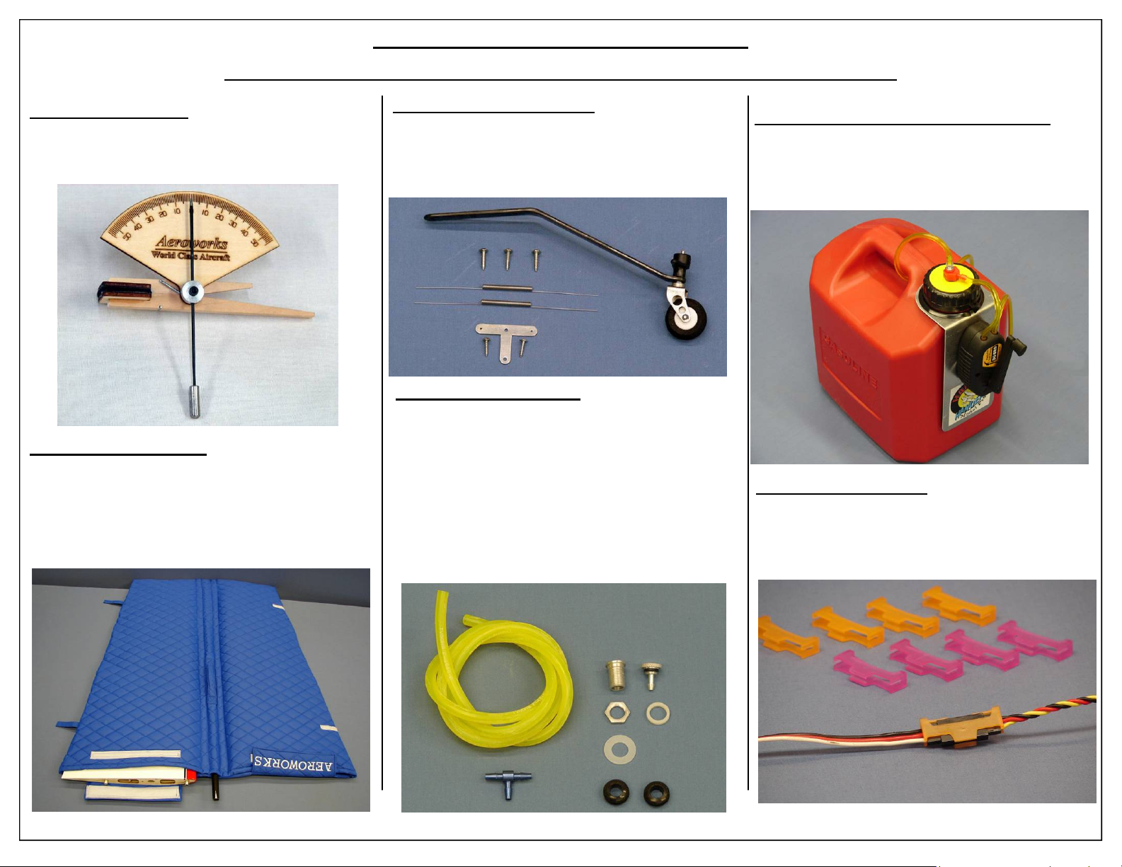
Accessories A vailable From Aeroworks
For more information or to order accessories visit our website: WWW.AERO-WORKS.NET
Custom Throw Meter
Use the Aeroworks Throw Meter to precisely set
your control throws on the elevator and ailerons.
Custom Wing/Stab Bags
Designed especially for the 30cc Bravata. The wing
and stab bags are lightweight, yet heavy enough to
protect your wings and stabs from hanger rash or
small nicks and dents from transporting too and
from the flying field.
5-15 LB Carbon Tail Wheel
This Carbon Tail Wheel is designed to fit perfectly
on the 30cc Bravata. The carbon leaf spring adds
tremendous strength compared to the stock alumi-
Fuel Line Installation Kit
The fuel line installation kit includes everything
needed to plumb your gasoline powered aircraft.
• 3 feet of 1/8” I.D. Dubro tygon tubing is pro-
vided.
• Simple ¼ turn fuel dot provides a nice, finished
look to any model.
• Aluminum fuel “T” with 1/8” I.D. will provide
superior fuel flow.
2.5 Gallon Gas Hand Crank Fuel System
The 2.5 Gallon Hand Crank fuel system is perfect
for pilots venturing into gas powered airplanes for
the first time. This gas can comes out of the box assembled and ready for use.
Aeroworks Safety Clips
Made from flexible plastic the Aeroworks Safety
Clips provide a easy and safe way to secure your
servo connections.
62 Aeroworks 30cc Bravata Assembly Manual
Page 63
Accessories A vailable From Aeroworks
For more information or to order accessories visit our website: WWW.AERO-WORKS.NET
Custom Float Set
Convert the 30cc Bravata to a unique float plane with the
Aeroworks float set. Made of High Quality fiberglass
with Steerable water rudders these floats will turn your
30cc Bravata into a versatile easy flying float plane.
DLE 30 Drill Guide
Never drill your props wrong again! This easy to use
propeller drill jig guide will allow you to quickly
drill props for your DLE 30.
RCexl Mini Tachometer
The RCexl Mini Tach will allow you to monitor engine
RPM while conveniently mounted inside the airplane.
Rcexl Opto Gas Engine Kill Switch
This device allows you to safely and remotely kill your
electronic ignition equipped engine from your transmitter.
The kill switch is Fiber Optically coupled to isolate your
ignition system from your radio system with No Interference. Easy Installation simply plugs into any spare channel in your receiver
30cc Bravata Custom Dash Panel
Dress up the cabin of your 30cc Bravata with this vintage
3 dimensional dash panel. Made from rigi d p l ast i c and
printed with a imitation wood grain finish this dash panel
will provide the finishing touch to your 30cc Bravata.
Vent Exit Dot
Clean up your fuel vent exit on the bottom of your
model with these clean looking vent exit dots. Machined from high quality aluminum these exit dots
are compatible with all fuel types.
Aeroworks 30cc Bravata Assembly Manual 63
Page 64

4903 Nome St, Denver, CO 80239
Phone: (303) 371-4222
Fax: (303) 371-4320
Email: [email protected]
Technical Support: Techsupport@Aero-Works.Net
Product Code
Turquoise/Cream:
ABRTC30
Deep Red/Cream:
ABRDRC30
Aeroworks, Inc
Aero-Works.Net
Printed: 02/2012
 Loading...