


Artisan Technology Group is your source for quality
new and certied-used/pre-owned equipment
• FAST SHIPPING AND
DELIVERY
• TENS OF THOUSANDS OF
IN-STOCK ITEMS
• EQUIPMENT DEMOS
• HUNDREDS OF
MANUFACTURERS
SUPPORTED
• LEASING/MONTHLY
RENTALS
• ITAR CERTIFIED
SECURE ASSET SOLUTIONS
SERVICE CENTER REPAIRS
Experienced engineers and technicians on staff
at our full-service, in-house repair center
Instra
Remotely inspect equipment before purchasing with
our interactive website at www.instraview.com
Contact us: (888) 88-SOURCE | sales@artisantg.com | www.artisantg.com
SM
REMOTE INSPECTION
View
WE BUY USED EQUIPMENT
Sell your excess, underutilized, and idle used equipment
We also offer credit for buy-backs and trade-ins
www.artisantg.com/WeBuyEquipment
LOOKING FOR MORE INFORMATION?
Visit us on the web at www.artisantg.com for more
information on price quotations, drivers, technical
specications, manuals, and documentation

BA-SINEDRIVE
USER’S MANUAL
P/N: EDU164 (V1.4)
AEROTECH, Inc. • 101 Zeta Drive • Pittsburgh, PA. 15238-2897 • USA
Phone (412) 963-7470 • Fax (412) 963-7459
Product Service: (412) 967-6440; (412) 967-6870 (Fax)
www.aerotech.com
Artisan Technology Group - Quality Instrumentation ... Guaranteed | (888) 88-SOURCE | www.artisantg.com

If you should have any questions about the BA- SineDrive or comm ents regar ding the documentation, please re fer to
Aerotech online at:
http://www.aerotech.com.
For your convenience, a product registration form is available at our web site.
Our web site is continually updated with new product information, free downloadable softwa re, firmware upgrades,
and special pricing on selected products.
The BA-SineDrive and BAS software are products of Aerotech, Inc.
Windows 95/NT are products of Microsoft Corporation.
The BA-SineDrive Use r’s Manual Revision History:
Version 1.0 July 17, 1998
Version 1.1 October 22, 1998
Version 1.2 September 19, 2000
Version 1.3 October 6, 2000
Version 1.4 November 20, 2000
© Aerotech, Inc., 2001
Artisan Technology Group - Quality Instrumentation ... Guaranteed | (888) 88-SOURCE | www.artisantg.com

BA SineDrive User’s Manual Table of Contents
TABLE OF CONTENTS
CHAPTER 1: INTRODUCTION............................................................................ 1-1
1.1. Product Overview............................................................................... 1-1
1.2. Velocity/Torque Amplifier.................................................................1-2
1.3. BAS DOS Software............................................................................ 1-3
1.4. BAS Windows Software Interface...................................................... 1-3
1.5. Hardware Overview and Function......................................................1-6
1.5.1. Motor and AC Power Connections....................................... 1-7
1.5.1.1. BAS 10/20/30..................................................... 1-7
1.5.1.2. BAS 50/75/100................................................... 1-8
1.5.2. Fusing and Inrush Limiting ..................................................1-9
1.5.2.1. BAS 10/20/30..................................................... 1-9
1.5.2.2. BAS 50/75/100................................................. 1-10
1.5.3. 20 - 80 Volt Option – BAS 10/20/30................................. 1-11
1.5.4. COM Port ........................................................................... 1-12
1.5.5. LED Status Indicators........................................................ 1-12
1.6. Safety Procedures and Warnings...................................................... 1-13
CHAPTER 2: CONFIGURATION AND COMMUNICATION........................... 2-1
2.1. Introduction........................................................................................ 2-1
2.2. BAS Control Board Jumper Selections.............................................. 2-1
2.3. BAS Communications Modes ............................................................ 2-2
2.4. Menu Commands................................................................................ 2-3
2.4.1. C-Change Parameter............................................................. 2-3
2.4.2. D-Display Tracking Information.......................................... 2-4
2.5. E - Display Error Message..................................................................2-6
2.5.1. BAS Faults........................................................................... 2-6
2.5.1.1. Invalid Hall Sequence ........................................2-6
2.5.1.2. RMS Current Error............................................. 2-6
2.5.1.3. Velocity Error..................................................... 2-6
2.5.1.4. Encoder Fault..................................................... 2-7
2.5.1.5. Thermistor Fault................................................. 2-7
2.5.1.6. RMS Current Error............................................. 2-7
2.5.2. F1- Abort Entry/Up One Menu Level ..................................2-7
2.5.3. F2/F3 - Previous/Next Menu................................................ 2-7
2.5.4. T - Transfer Parameters........................................................ 2-7
2.5.5. Space Bar ............................................................................. 2-7
2.5.6. CTRL-D............................................................................... 2-7
CHAPTER 3: PARAMETERS.................................................................................3-1
3.1. Introduction........................................................................................ 3-1
3.2. Parameters.......................................................................................... 3-1
3.2.1. PRM:1 Proportional Velocity Gain (KP)............................3-2
3.2.2. PRM:2 Integral Velocity Gain (KI).....................................3-2
3.2.3. PRM:3 Electronic Tach (VSCALE).................................... 3-2
3.2.4. PRM:4 Encoder Resolution (ENCODER).......................... 3-3
3.2.5. PRM:5 Electrical Cycles/Mechanical Revolution
(POLE PAIRS)..................................................................... 3-4
3.2.6. PRM:6 Hall Effects Available (HALLS) ............................ 3-4
Version 1.4 Aerotech, Inc. iii
Artisan Technology Group - Quality Instrumentation ... Guaranteed | (888) 88-SOURCE | www.artisantg.com

Table of Contents BA SineDrive User’s Manual
3.2.7. PRM:7 Initialization Current (INIT CURRENT)................ 3-5
3.2.8. PRM:8 Velocity Loop Update Rate (UPDATE)................ 3-6
3.2.9. PRM:9 Low Pass Filter Enable (FILTER).......................... 3-6
3.2.10. PRM:10 Filter Cutoff (CUT. FREQ.)..................................3-7
3.2.11. PRM:11 Commutation Phase Offset (PHASE OFF)...........3-7
3.2.12. PRM:12 Input Command Offset (CMD. OFF).................... 3-8
3.2.13. PRM:13,14 Current Offset Adjustment (IA OFFSET,
IB OFFSET).........................................................................3-8
3.2.14. PRM:15 Servo Peak Current Limit (CURR. LIMIT)..........3-9
3.2.15. PRM:16 Servo RMS Limit (RMS LIMIT)..........................3-9
3.2.16. PRM:17 Servo RMS Current Timeout (RMS TIME) .......3-10
3.2.17. PRM:18 Servo Velocity Trap (VEL ERR LMT).............. 3-10
3.2.18. PRM:19 Integral Clamp (INT CLAMP) ........................... 3-11
3.2.19. PRM:20 Operating Mode (MODE)................................... 3-11
3.2.20. PRM:21 Thermistor Polarity (THERM POL.)..................3-12
3.2.21. PRM:22 Enable Polarity (ENABLE POL.)....................... 3-13
3.2.22. PRM:23 Fault Output Polarity (FAULT POL.).................3-13
3.2.23. PRM:24 Encoder Polarity (Enc. Mult.)............................. 3-13
CHAPTER 4: MODE OF OPERATION AND TUNING.......................................4-1
4.1. Introduction........................................................................................ 4-1
4.2. Velocity and Current Mode................................................................4-1
4.2.1. Current Mode....................................................................... 4-1
4.2.2. Velocity Mode...................................................................... 4-2
4.3. Tuning.................................................................................................4-2
CHAPTER 5: TECHNICAL DETAILS...................................................................5-1
5.1. Introduction........................................................................................ 5-1
5.2. Hardware Overview and Function......................................................5-1
5.2.1. Motor and AC Power Connections....................................... 5-2
5.2.1.1. Wiring, Grounding, and Shielding
Techniques..........................................................5-2
5.2.1.2. Minimizing EMI Interference and CE
Compliance.........................................................5-2
5.2.1.3. Minimizing 50/60 HZ Line Interference.............5-3
5.2.2. COM Port.............................................................................5-4
5.2.3. LED Status Indicators ..........................................................5-5
5.3. The I/O Port........................................................................................5-6
5.3.1. SIN, SIN-N, COS, COS-N Signals.......................................5-6
5.3.2. Restore/Reset Signal.............................................................5-7
5.3.3. Input+/Input- Command INPUT .......................................... 5-7
5.3.4. Thermistor Input Signal........................................................ 5-7
5.3.5. External Enable Input........................................................... 5-8
5.3.6. Fault Output..........................................................................5-8
5.4. Encoder/Limits/Hall Effects Port........................................................ 5-9
5.4.1. Encoder Interface............................................................... 5-10
5.4.2. Hall Effect Interface...........................................................5-10
5.5. Servo Amplifier Specifications.........................................................5-14
5.6. BAS Amplifier Dimensions..............................................................5-15
5.6.1. Mounting Procedures for the BAS 10/20/30/50................. 5-17
5.6.2. Mounting Procedures for the BAS 75/100 .........................5-18
iv Aerotech, Inc. Version 1.4
Artisan Technology Group - Quality Instrumentation ... Guaranteed | (888) 88-SOURCE | www.artisantg.com

BA SineDrive User’s Manual Table of Contents
CHAPTER 6: TROUBLESHOOTING.................................................................... 6-1
6.1. Amplifier Related Problems ...............................................................6-1
APPENDIX A: WARRANTY AND FIELD SERVICE.......................................... A-1
APPENDIX A: WARRANTY AND FIELD SERVICE POLICY.......................... A-1
INDEX
∇ ∇ ∇
Version 1.4 Aerotech, Inc. v
Artisan Technology Group - Quality Instrumentation ... Guaranteed | (888) 88-SOURCE | www.artisantg.com

Table of Contents BA SineDrive User’s Manual
vi Aerotech, Inc. Version 1.4
Artisan Technology Group - Quality Instrumentation ... Guaranteed | (888) 88-SOURCE | www.artisantg.com

BA SineDrive User’s Manual List of Figures
LIST OF FIGURES
Figure 1-1. BA-SineDrive Amplifiers (10/20/30/50/75/100)................................1-1
Figure 1-2. Illustration of Configuration............................................................... 1-2
Figure 1-3. BAS MMI Main Screen...................................................................... 1-4
Figure 1-4. Parameter Screen................................................................................1-4
Figure 1-5. Parameter Information........................................................................ 1-5
Figure 1-6. BA-SineDrive Hardware (10/20/30)...................................................1-6
Figure 1-7. BA-SineDrive Hardware (50/75/100)................................................. 1-6
Figure 1-8. Motor and AC Power Connections – 10/20/30 Models..................... 1-7
Figure 1-9. Motor and AC Power Connections – 50/75/100 Models................... 1-8
Figure 1-10. Fuse and Inrush Limiting – 10/20/30 Models.................................... 1-9
Figure 1-11. AC Input Fusing – 50/75/100 Models.............................................. 1-10
Figure 1-12. 20 –80V Option................................................................................1-11
Figure 2-1. Tracking Screen.................................................................................. 2-2
Figure 2-2. Parameter Screen................................................................................2-2
Figure 2-3. The Change Parameter Screen............................................................ 2-3
Figure 2-4. Changing a Parameter in the Change Parameter Screen.....................2-4
Figure 2-5. Display Tracking Screen ....................................................................2-4
Figure 2-6. Display Error Message Screen............................................................2-6
Figure 3-1. PI Control Loop.................................................................................. 3-1
Figure 5-1. BA-SineDrive Hardware.................................................................... 5-1
Figure 5-2. Wiring to Minimize EMI and Capacitive Coupling............................5-3
Figure 5-3. Back-Propagation Line Filter Connection..........................................5-3
Figure 5-4. Isolatio n Transformer Connection (eliminates torque
disturbance)........................................................................................ 5-4
Figure 5-5. Over-Temperature Circuitry...............................................................5-7
Figure 5-6. Electrical Characteristics of Opto-Isolated Input................................5-8
Figure 5-7. Electrical Characteristics of Opto-Isolated Output.............................5-8
Figure 5-8. CW Motor Rotation (Viewed from the Mounting Flange End)........ 5-10
Figure 5-9. Encoder Input Circuit....................................................................... 5-10
Figure 5-10. Hall Effect Input Circuit................................................................... 5-11
Figure 5-11. Hall Effect Motor Phasing................................................................ 5-11
Figure 5-12. Motor Rotation (From Mounting Flange End) .................................5-12
Figure 5-13. Motor Phase Voltage Observation Scheme ......................................5-13
Figure 5-14. Encoder Phase Voltage Observation Scheme................................... 5-13
Figure 5-15. BAS Amplifier Dimensions (10/20/30)............................................5-15
Figure 5-16. BAS Amplifier Dimensions (50/75/100).......................................... 5-16
Figure 5-17. BAS Amp Top View (Preferred Mounting, 10/20/30/50)................5-17
Figure 5-18. Preferred Mounting of BAS Amplifiers (10/20/30/50).....................5-18
Figure 5-19. Preferred Mounting of BAS Amplifiers (75/100)............................. 5-19
∇ ∇ ∇
Version 1.4 Aerotech, Inc. vii
Artisan Technology Group - Quality Instrumentation ... Guaranteed | (888) 88-SOURCE | www.artisantg.com

List of Figures BA SineDrive User’s Manual
viii Aerotech, Inc. Version 1.4
Artisan Technology Group - Quality Instrumentation ... Guaranteed | (888) 88-SOURCE | www.artisantg.com

BA SineDrive User’s Manual List of Tables
LIST OF TABLES
Table 1-1. COM Port Pinouts............................................................................ 1-12
Table 2-1. Power Board Jumper Selections.........................................................2-1
Table 2-2. Control Board Jumper Selections.......................................................2-1
Table 2-3. Bit Patterns......................................................................................... 2-5
Table 3-1. Settings for Proportional Velocity Gain PRM:1................................. 3-2
Table 3-2. Settings for Integral Velocity Gain PRM:2........................................ 3-2
Table 3-3. Settings for Electronic Tach PRM:3................................................... 3-2
Table 3-4. Settings for Encoder Resolution PRM:4............................................. 3-3
Table 3-5. Settings for Electrical Cycles/Mechanical Revolution PRM:5........... 3-4
Table 3-6. Settings for Hall Effects Available PRM:6......................................... 3-4
Table 3-7. Settings for Initialization Current PRM:7........................................... 3-5
Table 3-8. Settings for Velocity Update Rate PRM:8.......................................... 3-6
Table 3-9. Settings for Low Pass Filter PRM:9 ...................................................3-6
Table 3-10. Settings for Filter Cutoff PRM:10...................................................... 3-7
Table 3-11. Settings for Phase Offset PRM:11......................................................3-7
Table 3-12. Settings for Input Command Offset PRM:12...................................... 3-8
Table 3-13. Settings for Position Mode PRM:13, PRM:14 ...................................3-8
Table 3-14. Settings for Servo Peak Current Limit PRM:15................................. 3-9
Table 3-15. Settings for Servo RMS Limit PRM:16.............................................. 3-9
Table 3-16. Settings for Servo RMS Current Timeout PRM:17..........................3-10
Table 3-17. Settings for Servo Velocity Trap PRM:18........................................ 3-10
Table 3-18. Settings for Integral Clamp PRM:19................................................ 3-11
Table 3-19. Operating Modes PRM:20................................................................3-11
Table 3-20. Settings for Operating Mode PRM:20..............................................3-12
Table 3-21. Settings for Thermistor Polarity PRM:21.........................................3-12
Table 3-22. Settings for Enable Polarity PRM:22 ............................................... 3-13
Table 3-23. Settings for Fault Output Polarity PRM:23 ......................................3-13
Table 3-24. Settings for Encoder Polarity PRM:24 .............................................3-13
Table 5-1. COM Port Pinouts.............................................................................. 5-4
Table 5-2. I/O Connector Pinouts (P1)................................................................ 5-6
Table 5-3. Pinouts for the Encoder/Limits/Hall Effects Port............................... 5-9
Table 5-4. Electrical Specifications................................................................... 5-14
Table 6-1. Amplifier Faults, Causes, and Solutions............................................. 6-1
∇ ∇ ∇
Version 1.4 Aerotech, Inc. ix
Artisan Technology Group - Quality Instrumentation ... Guaranteed | (888) 88-SOURCE | www.artisantg.com

List of Tables BA SineDrive User’s Manual
x Aerotech, Inc. Version 1.4
Artisan Technology Group - Quality Instrumentation ... Guaranteed | (888) 88-SOURCE | www.artisantg.com

BA SineDrive User’s Manual Regulatory Information
DECLARATION OF CONFORMITY
Manufacturer’s Name and Address
Aerotech, Inc.
101 Zeta Drive
Pittsburgh, PA 15238-2897
Declares that the product:
Product Name: BA Intellidrive/BA Sinedrive
Conforms to the following product specifications:
EMC: EN 55011: Class B Emissions
EN 50082-1: Immunity
EN61000-4-2
EN61000-4-3
EN61000-4-4
EN61000-4-11
EN50141
LVD: IEC 204-1
and complies with EMC directive 89/336/EEC.
Pittsburgh, PA David F. Kincel_________________________
October 8, 1998 Quality Assurance Manager
Robert Novotnak__________________________
Engineer Verifying Compliance
General notes concerning the test setup.
This product was tested at Compliance Labs, Middlefield, OH on October 8, 1998.
The brushless amplifier was tested with a brushless servo motor. To ensure that the
product passes the conducted emissions tests, a line filter and common mode choke must
be connected to the main inputs. The filter is a Schaffner FN 2070-10-06 and the common
mode choke is a Renco Electronics RL-1329-1200. Ferrite must be added to each line of
the main inputs but not earth ground. In order for the product to conform to the radiated
emission standards, the motor cable must be shielded and the shield must be tied to the
earth ground. Ferrite must also be added (in common mode) to the motor cable but not
around the shield. Finally, a metal 25-pin connector with a metal backshell must be used
when making a connection to the 25-pin receptacle on the amplifier. The shield of the
feedback cable must be tied to the metal backshell. Failure to follow the described
procedures may cause the amplifier/motor to exceed emission limits.
∇ ∇ ∇
Version 1.4 Aerotech, Inc. xi
Artisan Technology Group - Quality Instrumentation ... Guaranteed | (888) 88-SOURCE | www.artisantg.com

Regulatory Information BA SineDrive User’s Manual
xii Aerotech, Inc. Version 1.4
Artisan Technology Group - Quality Instrumentation ... Guaranteed | (888) 88-SOURCE | www.artisantg.com

BA SineDrive User’s Manual Preface
PREFACE
This section gives you an overview of topics covered in each of the sections of this
manual as well as conventions used in this manual. This manual contains information on
the following topics:
CHAPTER 1: INTRODUCTION
This chapter contains an introduction to the hardware and software architecture of the
BA-SineDrive.
CHAPTER 2: CONFIGURATION AND COMMUNICATION
This chapter covers the jumper configurations when used with a brush or brushless DC
motor. This chapter also covers the methods used to send commands to the BAS.
CHAPTER 3: PARAMETERS
This chapter describes the various parameters used on the BAS.
CHAPTER 4: MODE OF OPERATION
This chapter contains all information regarding the BAS’s modes of operation.
CHAPTER 5: TECHNICAL DETAILS
This chapter contains all detailed technical information regarding the BA-SineDrive.
CHAPTER 6: TROUBLESHOOTING
This chapter covers symptoms, probable causes, and solutions related to the BASineDrive.
APPENDIX A: WARRANTY AND FIELD SERVICE
Appendix A contains the warranty and field service policy for Aerotech products.
INDEX
The index contains a page number reference of topics discussed in this manual. Locator
page references in the index contain the chapter number (or appendix letter) followed by
the page number of the reference.
Version 1.4 Aerotech, Inc. xiii
Artisan Technology Group - Quality Instrumentation ... Guaranteed | (888) 88-SOURCE | www.artisantg.com

Preface BA SineDrive User’s Manual
CUSTOMER SURVEY FORM
A customer survey form is included at the end of this manual for the reader’s comments
and suggestions about this manual. Readers are encouraged to critique the manual and
offer their feedback by completing the form and either mailing or faxing it to Aerotech.
Throughout this manual the following conventions are used:
é The terms BA-SineDrive and BAS are used interchangeably throughout this
manual
é The text <ENTER> is used to indicate that the Enter/Return key on the
keyboard is to be pressed.
é Hexadecimal numbers are listed using a preceding "0x" (for example, 0x300,
0x12F, 0x01EA, etc.,) to distinguish them from decimal numbers
é Graphic icons or keywords may appear in the outer margins to provide visual
references of key features, components, operations or notes.
é This manual uses the symbol "∇ ∇ ∇" to indicate the end of a chapter.
Although every effort has been made to ensure consistency, subtle differences may exist
between the illustrations in this manual and the component and/or software screens that
they represent.
∇ ∇ ∇
xiv Aerotech, Inc. Version 1.4
Artisan Technology Group - Quality Instrumentation ... Guaranteed | (888) 88-SOURCE | www.artisantg.com

BA SineDrive User’s Manual Introduction
CHAPTER 1: INTRODUCTION
In This Section:
• Product Overview.....................................................1-1
• Velocity/Torque Amplifier ...................................... 1-2
• BAS DOS Software.................................................. 1-3
• Hardware Overview and Function............................ 1-6
• Safety Procedures and Warnings............................1-13
1.1. Product Overview
The BA-SineDrive (BAS) is a sine wave commutation amplifier (Figure 1-1). The BAS
incorporates a digital control board that allows velocity loop gains and parameters to be
set via PC RS-232. A simple DOS-based (or newer Windows-based) terminal program
supplied with the unit is used to communicate. The BAS10/20/30/50/75/100 are switching
Pulse Width Modulation (PWM) amplifiers. The amplifiers consist of an amplifier,
control board, and internal power supply.
Figure 1-1. BA-SineDrive Amplifiers (10/20/30/50/75/100)
Version 1.4 Aerotech, Inc. 1-1
Artisan Technology Group - Quality Instrumentation ... Guaranteed | (888) 88-SOURCE | www.artisantg.com

Introduction BA SineDrive User’s Manual
1.2. Velocity/Torque Amplifier
The BAS reads in a +/-10 volt signal and commutates a brushless motor with a sine wave
current command. Sine wave commutation is done via an encoder (quadrature input) and
provides the smoothest possible motion for a brushless motor. The input signal can be
either a velocity command or a torque (current) command. If the input signal is a current
command, a two-phase current command is sent directly to the amplifier. If the input
signal is a velocity command, the BAS closes the velocity loop digitally (using the
encoder, two controller gains and the velocity command). The output from the internal
control board is a two-phase current command to the amplifier.
The operating parameters are changed through the RS-232 interface. This interface is
menu driven and interfaces with either a hand held terminal or DOS emulation software.
All parameters are stored in flash memory. After the initial setup, the unit will boot in the
user-defined configuration. Figure 1-2 shows a typical configuration using the B AS.
Figure 1-2. Illustration of Configuration
1-2 Aerotech, Inc. Version 1.4
Artisan Technology Group - Quality Instrumentation ... Guaranteed | (888) 88-SOURCE | www.artisantg.com

BA SineDrive User’s Manual Introduction
1.3. BAS DOS Software
The BAS DOS software package is stored on a 1.44MB floppy disk, labeled “ BAS
Software Package.” The software includes a HT terminal emulator (com_bai.exe) and the
source files. The purpose of the com_bai.exe is to setup the BAS.
In order for the com_bai.exe to function correctly in DOS, the ansi.sys driver must be
added to the config.sys file.
DEVICE=c:\dos\ansi.sys
These programs can also run in a DOS shell under Windows 95/NT. Again, in order for
the com_bai.exe file to run correctly, the ansi.sys driver must be loaded. The following
examples illustrate how to load ansi.sys in Windows 95/NT.
For Windows 95, add the following line to the config.sys file.
device=c:\win95\command\ansi.sys
For Windows NT, add the following line to the config.nt file in the winnt\system32
directory.
device=%SystemRoot%\system32\ansi.sys
Restart the PC after making these changes.
The BAS must be in local mode to operate with the com_bai software. Pressing
CTRL-A will toggle between remote and local mode.
1.4. BAS Windows Software Interface
Included in the standard software package is the BAS Windows Software Interface. This
windows program is intended to take the place of the COM_BAI.EXE program for users
of Windows 95/98/NT.
To install the BAS Windows Software Interface:
1. Insert the BAS software CD into the CD-ROM drive of the PC.
2. From Windows 95/98/NT select the start button, then click Run, and type
“X:\Setup.exe” (where X is the drive letter corresponding to the CD-ROM
drive).
After the software has been installed, the program can be executed by double-clicking the
BASMMI icon.
In order for the MMI to communicate, the BAS be in remote mode. To enter remote
mode, run the com_bai.exe software in a DOS shell, and press CTRL-A.
Version 1.4 Aerotech, Inc. 1-3
Artisan Technology Group - Quality Instrumentation ... Guaranteed | (888) 88-SOURCE | www.artisantg.com

Introduction BA SineDrive User’s Manual
Figure 1-3. BAS MMI Main Screen
The BAS MMI interface is a graphical interface that allows the user to quickly view all
the parameters available on the SineDrive and make any adjustments that are required.
The parameters on the system are divided up by type. Select the button on the left for the
type of parameters that you wish to view/edit. Also available on this sub-menu is a
diagnostic utility and a setup utility for airing in configuring the unit. The Online Help
file (selectable from the Help menu) contains more information on these utilities.
To view the maximum and minimum value for any parameter, place , the mouse pointer
over the name of the parameter and the name will become highlighted. Click and hold the
left mouse button to see the parameter , range. Releasing the mouse button will hide the
range.
Figure 1-4. Parameter Screen
1-4 Aerotech, Inc. Version 1.4
Artisan Technology Group - Quality Instrumentation ... Guaranteed | (888) 88-SOURCE | www.artisantg.com

BA SineDrive User’s Manual Introduction
To view more information about a parameter (such as the purpose of a parameter or the
units associated with a parameter,), click on the right mouse button while the parameter
name is highlighted.
Figure 1-5. Parameter Information
Version 1.4 Aerotech, Inc. 1-5
Artisan Technology Group - Quality Instrumentation ... Guaranteed | (888) 88-SOURCE | www.artisantg.com

Introduction BA SineDrive User’s Manual
1.5. Hardware Overview and Function
The BA-SineDrive consists of two power connections (motor power and input power),
two LED indicator lamps, and three “D” style connectors. Refer to Figure 1-6 and
Figure 1-7 for locations.
AC Power
Motor
Connections
LED Status
Indicators
COM Port
P2
I/O Port
P1
Encoder/Limits/Hall
Effects Port
P3
Figure 1-6. BA-SineDrive Hardware (10/20/30)
AC Power
Motor
Connections
LED Status
Indicators
COM Port
P2
Encoder/Limits/Hall
Effects Port
P3
I/O Port
P1
Figure 1-7. BA-SineDrive Hardware (50/75/100)
1-6 Aerotech, Inc. Version 1.4
Artisan Technology Group - Quality Instrumentation ... Guaranteed | (888) 88-SOURCE | www.artisantg.com

BA SineDrive User’s Manual Introduction
1.5.1. Motor and AC Power Connections
1.5.1.1. BAS 10/20/30
For the BAS10, 20 and 30, AC power is applied to the BAS through the AC receptacle
located on the front of the unit. The power cord is similar to the type used with personal
computers. The motor co nnection is made through the terminal strip located on the front
of the BAS. This connector contains the motor connections along with the earth ground
connection.
Motor Connection
AC Power
Motor
Cables
BM
Motor
110VAC or
220VAC
Figure 1-8. Motor and AC Power Connections – 10/20/30 Models
Version 1.4 Aerotech, Inc. 1-7
Artisan Technology Group - Quality Instrumentation ... Guaranteed | (888) 88-SOURCE | www.artisantg.com

Introduction BA SineDrive User’s Manual
1.5.1.2. BAS 50/75/100
AC power is applied to the B AS through the terminal strip on the front of the unit. T he
motor connections and e arth ground connectio ns are also made thr ough the terminal strip
located on the front of the BAS.
Auxiliary Power
Input
AC1
AC2
AC3
Ground
Motor Connector A
Motor Connector B
Motor Connector C
Ground
Figure 1-9. Motor and AC Power Connections – 50/75/100 Models
1-8 Aerotech, Inc. Version 1.4
Artisan Technology Group - Quality Instrumentation ... Guaranteed | (888) 88-SOURCE | www.artisantg.com

BA SineDrive User’s Manual Introduction
1.5.2. Fusing and Inrush Limiting
1.5.2.1. BAS 10/20/30
The BAS 10/20/30 do not contain a fuse or any inrush limiting internally. These can be
added externally to the AC input as shown in Figure 1-10.
RECOMMENDED MODELS:
BAS SERIES
THERMISTOR AND FUSING
RODAN SURGE GIARD SG100 (20A RMS)
KEYSTONE CL-10 (12A RMS)
AMETHERM #SL32IRO30 (30A RMS)
RECOMMENDED FUSE VALUE S:
BAS10 10 ASB
BAS20
BAS30
20 ASB
/2
+,
*<(/
%/8
%51
)86(
$&
,QSXW
DUE TO CAPACITIVE NATURE OF AMPLIFIER INPUT CIRCUIT,
CURRENT INRUSH LIMITING IS RECOMMENDED. NEGATIVE
TEMPERATURE COEFFICIENT THERMISTORS CAN BE USED
FOR THIS PURPOSE. THERMISTOR IS TO BE PLACED IN THE
AC HI LINE. ONLY ONE THERMISTOR NEEDED FOR ONE AMP.
ALTERNATELY, 2 THERMISTORS CAN BE USED IN AC HI & LO
FOR MULTIPLE AMPS IN PARALLEL.
Figure 1-10. Fuse and Inrush Limiting – 10/20/30 Models
Version 1.4 Aerotech, Inc. 1-9
Artisan Technology Group - Quality Instrumentation ... Guaranteed | (888) 88-SOURCE | www.artisantg.com

Introduction BA SineDrive User’s Manual
1.5.2.2. BAS 50/75/100
The BAS 50/75/100 contain inrush limiting internally. Fusing can be added if needed
externally (refer to Figure 1-11). The BAS 50 requires 2 phase input power while the
BAS 75/100 require 3 phase input power. Earth ground should be connected to the earth
ground connection on the unit. Motor connections are made through the A, B, and C
connections on the front of the unit.
BAS SERIES
FUSING
AC3
A.C.
Input
AC2
AC1
FUSES
Figure 1-11. AC Input Fusing – 50/75/100 Models
1-10 Aerotech, Inc. Version 1.4
Artisan Technology Group - Quality Instrumentation ... Guaranteed | (888) 88-SOURCE | www.artisantg.com
BA SineDrive User’s Manual Introduction
(L)
(H)
TB1
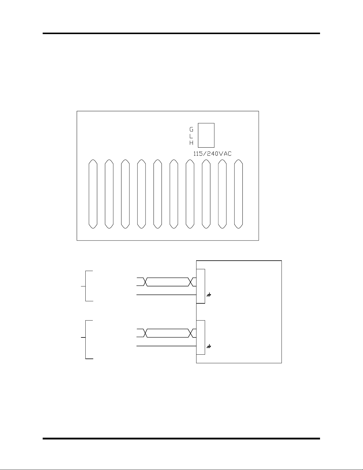
1.5.3. 20 - 80 Volt Option – BAS 10/20/30
If a BAS 10/20/30 - 80 amplifier was purchased, a separate AC input has been included
on the side of the amplifier. The internal power supply of the BAS amplifier requires a
minimum of 80VAC input to operate properly. Figure 1-12 shows the connection to the
separate AC power board. The connection is made to the AC input board with a three
terminal connector (Aerotech Part # ECK00213).
CONTROL
A.C.
BUS
A.C.
115VAC
OR
230VAC
14VAC
TO
56VAC
(DEPENDING
ON MODEL)
HI
LO
FRAME
HI
LO
FRAME
Figure 1-12. 20 –80V Option
J1
1
HI
2 3 LO
(G)
5
HI
6
LO
4
BAS
AMPLIFIER
Version 1.4 Aerotech, Inc. 1-11
Artisan Technology Group - Quality Instrumentation ... Guaranteed | (888) 88-SOURCE | www.artisantg.com

Introduction BA SineDrive User’s Manual
1.5.4. COM Port
The COM port is a standard 9-pin “D” style connector located on the front of the BAS
(refer to Figure 1-6). It consists of two signal lines; transmit (TXD) and receive (RXD), a
ground, shield, and a 5V power supply line used to power the Aerotech Hand held
Terminal (HHT). Table 1-1 contains the connector pinouts. The BAS is configured as
Data Terminal Equipment (DTE); therefore, a NULL MODEM cable is required to
connect to the PC. This swaps pins 2 and 3 for proper communication.
Table 1-1. COM Port Pinouts
Pins Function
1Shield
2 Receive (RXD)
3 Transmit (TXD)
4,6,7,8 NC
5 Ground (GND)
9+5 V
The baud rate is 9600, with no parity (one stop bit).
The 5 Volt connection on COM port is for the hand held terminal and is a nonstandard connection.
1.5.5. LED Status Indicators
The BAS contains two LED’s located on the front of the unit that indicate the fault status
of the unit, refer to Figure 1-6. One of the LED’s indicates if power is applied to the unit,
the second indicates the status of the amplifier. A green light indicates the amplifier is in
the ready state and the motor is enabled, while a red light indicates a fault or the power
stage is disabled.
1-12 Aerotech, Inc. Version 1.4
Artisan Technology Group - Quality Instrumentation ... Guaranteed | (888) 88-SOURCE | www.artisantg.com

BA SineDrive User’s Manual Introduction
1.6. Safety Procedures and Warnings
The following statements apply wherever the Warning or Danger symbol appears within
this manual. Failure to observe these precautions could result in serious injury to those
performing the procedures and/or damage to the equipment.
To minimize the possibility of electrical shock and bodily injury, ensure that the
motor is decoupled from the mechanical system and no harm to personnel will result
if the motor begins to spin.
Before performing the following steps, ensure that the motor is completely
disconnected from the amplifier and the associated mechanical system.
To minimize the possibility of electrical shock and bodily injury when any electrical
circuit is in use, ensure that no person is exposed to the circuitry.
WARNING
WARNING
To minimize the possibility of bodily injury, make certain that all electrical power
switches (all switches external to the amplifier) are in the off position prior to making
any mechanical adjustments.
∇ ∇ ∇
Version 1.4 Aerotech, Inc. 1-13
Artisan Technology Group - Quality Instrumentation ... Guaranteed | (888) 88-SOURCE | www.artisantg.com

Introduction BA SineDrive User’s Manual
1-14 Aerotech, Inc. Version 1.4
Artisan Technology Group - Quality Instrumentation ... Guaranteed | (888) 88-SOURCE | www.artisantg.com
BA SineDrive User’s Manual Configuration and Communication
CHAPTER 2: CONFIGURATION AND COMMUNICATION
In This Section:
• Introduction ........................................................................................ 2-1
• BAS Control Board Jumper Selections ...............................................2-1
• BAS Communications Modes .............................................................2-2
• Menu Commands.................................................................................2-3
2.1. Introduction
This chapter covers the jumper configurations when used with a brushless DC motor.
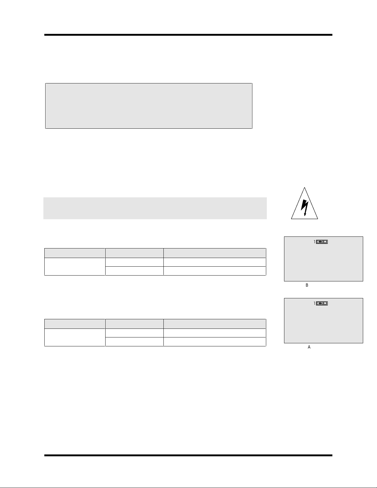
2.2. BAS Control Board Jumper Selections
The only user selectable jumper on the BAS Amplifier board is JP2. The jumper selects
between shunt and no shunt regulator.
Remove power from unit before changing the jumper.
The user selectable jumper on the power board is shown in Table 2-1.
Table 2-1. Power Board Jumper Selections
Jumper Position Mode
JP2
1-2 No shunt
2-3 Shunt board installed
The only user selectable jumper on the control board is JP2. It selects the input common
resistance. Refer to Table 2-2.
Table 2-2. Control Board Jumper Selections
Jumper Position Mode
JP2
1-2 5V Opto input
2-3 24V Opto input
DANGER
JP2
BAS Power Board
JP2
BAS Control Board
Version 1.4 Aerotech, Inc. 2-1
Artisan Technology Group - Quality Instrumentation ... Guaranteed | (888) 88-SOURCE | www.artisantg.com
Configuration and Communication BA SineDrive User’s Manual
2.3. BAS Communications Modes
Using either the hand held terminal (HT) or the DOS emulation program, the first screen
the user will see is shown in Figure 2-1. This is the tracking screen (com_bai). This
program can be used with BA-Intellidrive (BAI) or BAS.
Figure 2-1. Tracking Screen
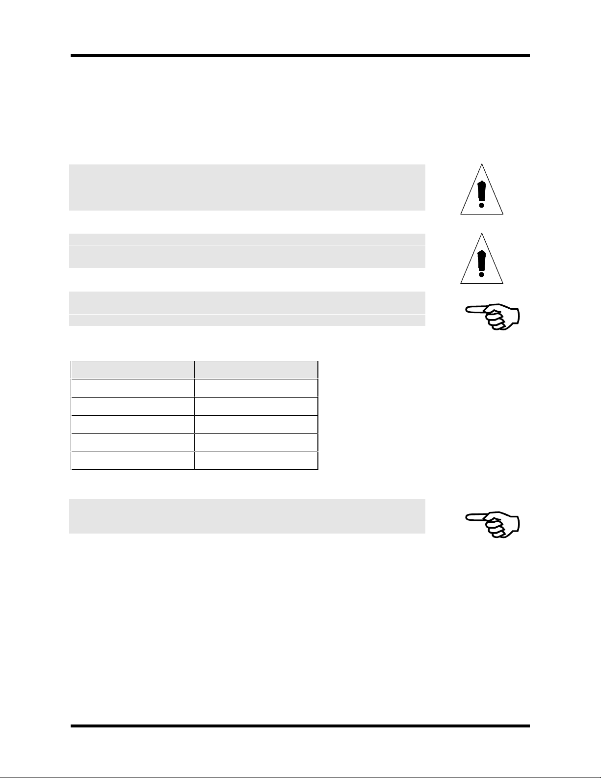
Pressing any key will take the user to the parameters screen. This screen is shown in
Figure 2-2.
Figure 2-2. Parameter Screen
2-2 Aerotech, Inc. Version 1.4
Artisan Technology Group - Quality Instrumentation ... Guaranteed | (888) 88-SOURCE | www.artisantg.com

BA SineDrive User’s Manual Configuration and Communication
2.4. Menu Commands
The BAS uses certain menu commands that allow the user to perform specific functions.
The first two parameters the user sees are the velocity loop gains. The fourth row shows
menu driven commands C, D, E, and T. The letter commands can be entered while in the
parameters screen. Pressing the letter immediately prompts the user for the next action.
These are described below.
1) C - Change a parameter.
2) D - Display tracking information.
3) E – Error Messages.
4) T - Transfer Parameters.
5) CTRL-D Reset the BAS.
F1 – Abort entry/return to previous menu.
F2/F3 – Previous or N ext menu.
<space> - cycles through menu commands.
2.4.1. C-Change Parameter
This command allows the user to change a parameter displayed on the screen, refer to
Figure 2-3. After pressing C, the user is prompted for the parameter they want to change.
To change the parameter, type in the number, press <ENTER> and the parameter is
changed and saved to the flash memory. Some parameters may not take effect until
issuing a reset. These parameters are discussed in Chapter 3: Parameters. Pressing the
F1 key aborts changing the pa rameter.
Figure 2-3. The Change Parameter Screen
Version 1.4 Aerotech, Inc. 2-3
Artisan Technology Group - Quality Instrumentation ... Guaranteed | (888) 88-SOURCE | www.artisantg.com

Configuration and Communication BA SineDrive User’s Manual
All parameters have upper and lower bounds. These bounds are provided in Chapter 3:
Parameters. If the user enters a number for a parameter which is out of the allowable
range, an error message appears. See the example in Figure 2-4, below.
Figure 2-4. Changing a Parameter in the Change Parameter Screen
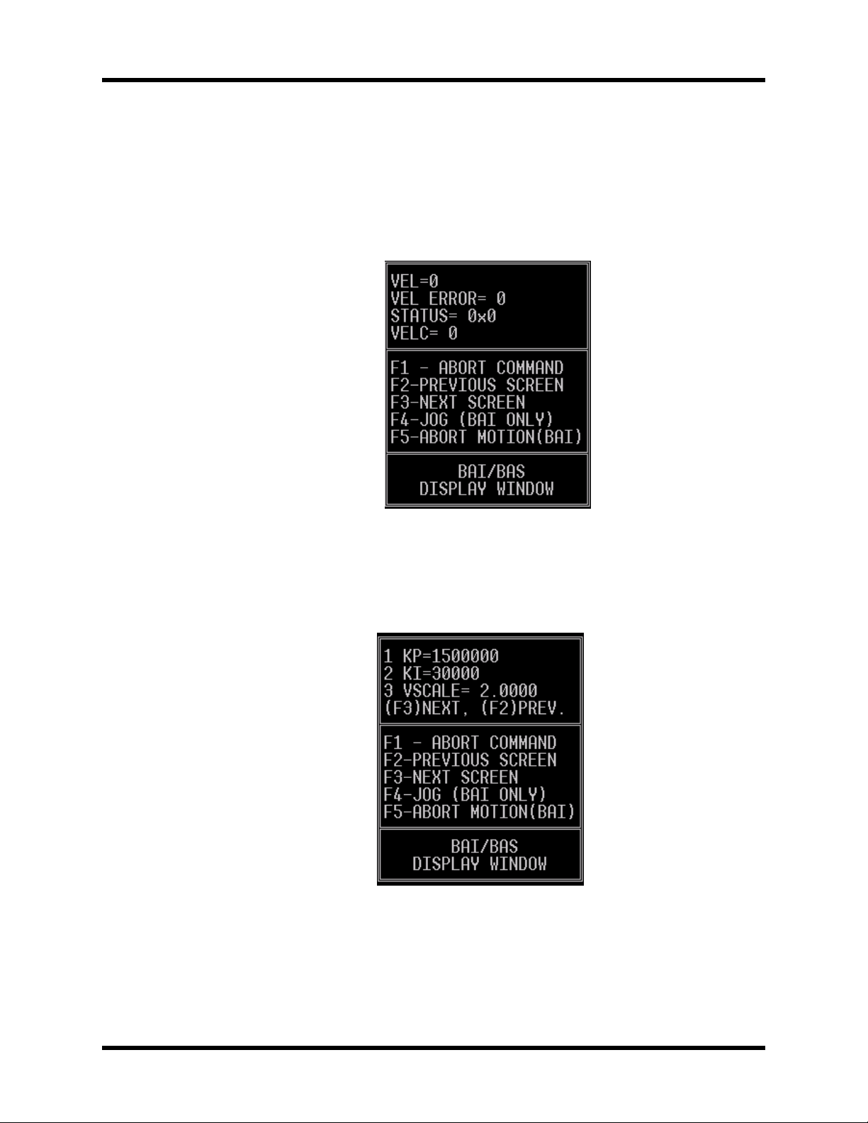
2.4.2. D-Display Tracking Information
After pressing the D key, the user will see the following screen in Figure 2-5.
Figure 2-5. Display Tracking Screen
2-4 Aerotech, Inc. Version 1.4
Artisan Technology Group - Quality Instrumentation ... Guaranteed | (888) 88-SOURCE | www.artisantg.com

BA SineDrive User’s Manual Configuration and Communication
This screen shows the real time tracking display of the BAS. The velocity, velocity error,
status, and velocity command are shown. Status shows the current status of the BAS. The
bit patterns are shown in Table 2-3.
Table 2-3. Bit Patterns
Bit # Function
bit 0: Reserved
bit 1: Reserved
bit 2: Reserved
bit 3: Reserved
bit 4: Fault
bit 5: Reserved
bit 6: Reserved
bit 7: Reserved
See Section 2.5. for types of errors.
Version 1.4 Aerotech, Inc. 2-5
Artisan Technology Group - Quality Instrumentation ... Guaranteed | (888) 88-SOURCE | www.artisantg.com

Configuration and Communication BA SineDrive User’s Manual
2.5. E - Display Error Message
When an error occurs during operation, an error message will be generated. Errors can
occur from velocity error faults, amplifier faults or any other external fault. To display
these error messages, the error message selection should be chosen from the menu. Refer
to Figure 2-6.
Figure 2-6. Display Error Message Screen
2.5.1. BAS Faults
The BAS continually monitors different aspects of the amp/motor/encoder/control every
1ms for fault conditions. The possible fault conditions are listed below.
2.5.1.1. Invalid Hall Sequence
There are two invalid hall states that will cause the BAS to fault. They are the 000 and
111 states. The 111 state can occur if the encoder is not plugged into the BAS encoder
port. When initializing without halls, the BAS will ignore this fault.
2.5.1.2. RMS Current Error
PRM:16 and 17 will set the RMS fault threshold. The BAS uses averaging to monitor the
current command during operation. If the current command stays above the threshold too
long, the amplifier will fault.
2.5.1.3. Velocity Error
PRM:18 sets the max allowable velocity error before a fault occurs.
2-6 Aerotech, Inc. Version 1.4
Artisan Technology Group - Quality Instrumentation ... Guaranteed | (888) 88-SOURCE | www.artisantg.com

BA SineDrive User’s Manual Configuration and Communication
2.5.1.4. Encoder Fault
This fault will occur if an encoder is not present or if the BAS receives invalid signals
during operation.
2.5.1.5. Thermistor Fault
The thermistor can be used to monitor the motor. If the motor temperature is too high, the
BAS will detect this condition and generate a fault. Since many motors do not have
thermistors, PRM:21 can be used to disable this fault condition.
2.5.1.6. RMS Current Error
The above mentioned faults are all monitored by the software. In addition, there is
hardware on the BAS that also monitors the faults of the power stage. These faults are
listed below. Whenever the error message is AMP FAULT, one of the following has
occurred (note that the source of this fault cannot be easily determined):
• Over temperature
• Bias supply too low
• +5V too low
• RMS current (this is also monitored by the software and cannot be changed)
• Output short circuit
• DC bus over-voltage (if this occurs, a shunt board may be required).
2.5.2. F1- Abort Entry/Up One Menu Level
Pressing F1 aborts the current menu operation or moves up one level in the menu.
2.5.3. F2/F3 - Previous/Next Menu
This command allows the user to change the displayed parameters. The parameter
screens are circular, (i.e., if the user continually presses F3 or F2, they will eventually
return to the starting screen).
2.5.4. T - Transfer Parameters
Pressing "T" p ermits the user to upload or download parameters to their PC. The user is
queried to enter the file. File names follow the 8.3 convention and can co ntain numbers or
letters.
2.5.5. Space Bar
Pressing the space bar cycles through the available commands on the top level menu.
2.5.6. CTRL-D
Pressing "CTRL-D" issues a reset to the BAS. This is needed to clear any fault(s)
∇ ∇ ∇
Version 1.4 Aerotech, Inc. 2-7
Artisan Technology Group - Quality Instrumentation ... Guaranteed | (888) 88-SOURCE | www.artisantg.com

Configuration and Communication BA SineDrive User’s Manual
2-8 Aerotech, Inc. Version 1.4
Artisan Technology Group - Quality Instrumentation ... Guaranteed | (888) 88-SOURCE | www.artisantg.com

BA SineDrive User’s Manual Parameters
CHAPTER 3: PARAMETERS
In This Section:
• Introduction ...................................................................3-1
• Parameters ......................................................................3-1
3.1. Introduction
This chapter describes the various parameters used on the BAS. All parameters are
entered as numbers.
3.2. Parameters
The servo loop parameters dictate the performance of the BAS’s operation. A block
diagram of the BAS’s velocity loop can been seen in Figure 3-1.
External Velocity
Command
PRM:20=2
Extern al Current
²
PRM:3
VSCALE
Velocity Feedback
from Encoder
KP
(PRM:1)
Kl/s
(PRM:2)
Command
Low Pass Filter
PRM:9, PRM:10
PRM:20=2
PRM:20=1, 2
Figure 3-1. PI Control Loop
The text in parentheses () following the parameter names in the section headings are
the abbreviation for that parameter as seen on the display.
To AMP
To AMP
Sine Wave
Commutation
(PRM:4, PRM:5)
Version 1.4 Aerotech, Inc. 3-1
Artisan Technology Group - Quality Instrumentation ... Guaranteed | (888) 88-SOURCE | www.artisantg.com

Parameters BA SineDrive User’s Manual
3.2.1. PRM:1 Proportional Velocity Gain (KP)
This parameter provides proportional gain adjustment to the velocity error mode of the PI
Control loop, refer to Table 3-1.
Table 3-1. Settings for Proportional Velocity Gain PRM:1
PRM:1 Settings
Default Value 750000
Maximum Value 2147483647
Minimum Value 0
Type Long (32 bit)
Units -
3.2.2. PRM:2 Integral Velocity Gain (KI)
This parameter provides integral gain adjustment to the velocity error mode of the PI
Control loop, refer to Table 3-2.
Table 3-2. Settings for Integral Velocity Gain PRM:2
PRM:2 Settings
Default Value 35000
Maximum Value 2147483647
Minimum Value 0
Type Long (32 bit)
Units -
3.2.3. PRM:3 Electronic Tach (VSCALE)
This parameter scales the velocity from the encoder. It is primarily used as a tach gain for
the velocity derived from the encoder. Refer to Table 3-3 for parameter settings.
Table 3-3. Settings for Electronic Tach PRM:3
PRM:3 Settings
Default Value 4
Maximum Value 1000
Minimum Value -1000
Units -
A negative value can be used to change the polarity of the velocity.
3-2 Aerotech, Inc. Version 1.4
Artisan Technology Group - Quality Instrumentation ... Guaranteed | (888) 88-SOURCE | www.artisantg.com

BA SineDrive User’s Manual Parameters
Vscale can be used to define the maximum speed the motor will move with a ± 10V input.
It can be calculated as follows:
90.40
Vscale
=
revX
=
z
sec
Where X rev/sec and counts/rev can be replaced by m/s for linear motors.
3.2.4. PRM:4 Encoder Resolution (ENCODER)
The encoder resolution is only needed for commutation. For rotary motors, this value
represents the line count of the encoder times 4. For example, if the resolution of the
encoder is 1000 (1000 lines/revolution), the user would enter 4000 for this parameter.
The multiplication by four is done in hardware on the controller.
z
Y
sec1
PRM
counts
8:/6000
rev
For linear motors, this number represents the number of counts for one electrical cycle.
For example, if a linear motor has an electrical cycle of 2.4 inches, and the encoder
resolution is 1µm, then the user would enter
Refer to Table 3-4 for parameter settings.
Requires a reset (CTRL-D) before taking effect.
Table 3-4. Settings for Encoder Resolution PRM:4
PRM:4 Settings
Default Value 4000
Maximum Value 2147483647
Minimum Value 300
Type Long (32 bit)
in
mmin
6
countsx
m
1000
11014.254.2
m
mm
60960
=
counts
Units Counts
Version 1.4 Aerotech, Inc. 3-3
Artisan Technology Group - Quality Instrumentation ... Guaranteed | (888) 88-SOURCE | www.artisantg.com

Parameters BA SineDrive User’s Manual
3.2.5. PRM:5 Electrical Cycles/Mechanical Revolution
(POLE PAIRS)
This parameter is the number of electrical cycles of the motor/mechanical revolution for
brushless motors. Also known as the number of pole-pairs. For linear motors, this PRM:5
should be one. Refer to Table 3-5 for parameter settings.
Requires a reset (CTRL-D) before taking effect.
Table 3-5. Settings for Electrical Cycles/Mechanical Revolution PRM:5
PRM:5 Settings
Default Value 4
Maximum Value 20
Minimum Value 1
Type Long (32 bit)
Units -
3.2.6. PRM:6 Hall Effects Available (HALLS)
If the motor has Hall effects available (PRM:6=1), the controller uses the halls to
initialize the commutation table. If the hall signals are not available or are not recognized
by the controller, the user should set this value to 0. If this value is 0, the controller
attempts to initialize the motor by energizing the phases to a known rotor position and
then commutate via the encoder from this known value. The peak current used to
energize the phases is given in PRM:7. Refer to Table 3-6 for parameter (PRM:6)
settings.
Requires a reset (CTRL-D) before taking effect.
If the user uses this method to initialize the motor on a linear stage, ensure that the stage
is not near a hardware limit.
Table 3-6. Settings for Hall Effects Available PRM:6
PRM:6 Settings
Default Value 1(Halls available)
Maximum Value 1
Minimum Value 0
Type Long (32 bit)
Units -
This method will not work on vertical stages.
3-4 Aerotech, Inc. Version 1.4
Artisan Technology Group - Quality Instrumentation ... Guaranteed | (888) 88-SOURCE | www.artisantg.com
BA SineDrive User’s Manual Parameters
3.2.7. PRM:7 Initialization Current (INIT CURRENT)
This parameter defines the peak current sent to the motor during an initialization. T his
only applies to brushless motors without hall signals (PRM:6=0). The value of this
parameter is in percent (%). Refer to Table 3-7 for parameter settings.
Care must be taken to ensure that the peak current applied to the motor does not
exceed the motor’s ratings.
IMPORTANT
Motor may jump during initialization. This is normal.
WARNING
Requires a reset (CTRL-D) before taking effect.
Table 3-7. Settings for Initialization Current PRM:7
PRM:7 Settings
Default Value 20
Maximum Value 100
Minimum Value 0
Type Long (32 bit)
Units % of Peak
The motor should not be in a limit.
Version 1.4 Aerotech, Inc. 3-5
Artisan Technology Group - Quality Instrumentation ... Guaranteed | (888) 88-SOURCE | www.artisantg.com
Parameters BA SineDrive User’s Manual
3.2.8. PRM:8 Velocity Loop Update Rate (UPDATE)
This parameter determines the velocity loop update time. The default value of 3
corresponds to a velocity loop update time of .5ms. Refer to Table 3-8 for parameter
settings. To compute the velocity loop update time, use the following formula:
Velocity loop update time = PRM:8/6000
Requires a reset (CTRL-D) before taking effect.
Table 3-8. Settings for Velocity Update Rate PRM:8
PRM:8 Settings
Default Value 3
Maximum Value 20
Minimum Value 1
Type Long (32 bit)
Units -
3.2.9. PRM:9 Low Pass Filter Enable (FILTER)
A low-pass filter can be inserted after sampling the torque/vel command by setting this
parameter to 1. The cutoff frequency is given in PRM:10. This can be used to smooth
out converter noise on the input command. Refer to Table 3-9 for parameter settings.
Requires a reset (CTRL-D) before taking effect.
Table 3-9. Settings for Low Pass Filter PRM:9
PRM:9 Settings
Default Value 0 (filter is not enabled)
Maximum Value 1
Minimum Value 0
Type Long (32 bit)
Units -
3-6 Aerotech, Inc. Version 1.4
Artisan Technology Group - Quality Instrumentation ... Guaranteed | (888) 88-SOURCE | www.artisantg.com

BA SineDrive User’s Manual Parameters
3.2.10. PRM:10 Filter Cutoff (CUT. FREQ.)
This parameter defines the cutoff frequency for the low-pass filter. The low pass filter
filters the current command from the PI loop. Refer to Table 3-10 for parameter settings.
Table 3-10. Settings for Filter Cutoff PRM:10
PRM:10 Settings
Default Value 500.0
Maximum Value 20000.0
Minimum Value 0
Type Float
Units Hz
3.2.11. PRM:11 Commutation Phase Offset (PHASE OFF)
This parameter allows the user to shift the commutation table by the value in PRM:11.
This parameter can be used if phase offsets occur in the current commands, (i.e., if the
current commands are out of phase with the back-emf of the motor). A phase shift can
occur if the hall signals are not aligned properly. Refer to Table 3-11 for parameter
settings.
This parameter can also be used to shift the commutation table for different Hall effect
schemes.
Requires a reset (CTRL-D) before taking effect.
Table 3-11. Settings for Phase Offset PRM:11
PRM:11 Settings
Default Value 0
Maximum Value 359
Minimum Value -359
Type Long (32 bit)
Units Degrees
Aerotech motors have a phase offset of 0°. Other vendors typically set it to 30°. Refer to
Section 5.4.2. for details on phasing
Version 1.4 Aerotech, Inc. 3-7
Artisan Technology Group - Quality Instrumentation ... Guaranteed | (888) 88-SOURCE | www.artisantg.com

Parameters BA SineDrive User’s Manual
3.2.12. PRM:12 Input Command Offset (CMD. OFF)
This parameter allows the user to correct for offsets in the external analog circuitry when
operating in velocity mode. Refer to Table 3-12 for parameter settings.
Table 3-12. Settings for Input Command Offset PRM:12
PRM:12 Settings
Default Value 0
Maximum Value 50000
Minimum Value -50000
Type Long (32 bit)
Units
3.2.13. PRM:13,14 Current Offset Adjustment (IA OFFSET, IB
OFFSET)
This parameter can be used to null out an offset in the current commands. PRM:13 is for
phase A and PRM:14 is for phase B. This value is added before the current commands
are sent to the DAC. Refer to Table 3-13 for parameter settings.
Table 3-13. Settings for Position Mode PRM:13, PRM:14
PRM:13, PRM:14 Settings
Default Value 0
Maximum Value 2048
Minimum Value -2048
Type Long (32 bit)
Units -
3-8 Aerotech, Inc. Version 1.4
Artisan Technology Group - Quality Instrumentation ... Guaranteed | (888) 88-SOURCE | www.artisantg.com

BA SineDrive User’s Manual Parameters
3.2.14. PRM:15 Servo Peak Current Limit (CURR. LIMIT)
This parameter controls the maximum allowable current that the PI loop can output. The
value is expressed in % of the amplifier’s peak current output. For example, if the
amplifier can output a peak current of 20 Amps, and PRM:15 is 50%, then the peak
current from the PI loop will be 10 Amps. Refer to Table 3-14 for parameter settings.
Table 3-14. Settings for Servo Peak Current Limit PRM:15
PRM:15 Settings
Default Value 100
Maximum Value 100
Minimum Value 0
Type Long (32 bit)
Units Percent (%)
Requires a reset (CTRL-D) before taking effect.
3.2.15. PRM:16 Servo RMS Limit (RMS LIMIT)
This parameter sets the RMS current limit that the PI loop can output before a fault
occurs. The value is expressed in % of the amplifier’s RMS current capability. For
example, if the amplifier has an RMS current rating of 10 Amps, and PRM:16 is 50%,
then the controller will generate a fault if the RMS current exceeds 5 Amps for longer
than the time given in PRM:17. Refer to Table 3-15 for parameter settings.
Table 3-15. Settings for Servo RMS Limit PRM:16
PRM:16 Settings
Default Value 20
Maximum Value 100
Minimum Value 0
Type Long (32 bit)
Units Percent (%)
Requires a reset (CTRL-D) before taking effect.
Version 1.4 Aerotech, Inc. 3-9
Artisan Technology Group - Quality Instrumentation ... Guaranteed | (888) 88-SOURCE | www.artisantg.com
Parameters BA SineDrive User’s Manual
3.2.16. PRM:17 Servo RMS Current Timeout (RMS TIME)
This parameter determines how long the current can remain above the RMS threshold
(given in PRM:16) before a fault is generated. Refer to Table 3-16 for p a rameter settings.
Table 3-16. Settings for Servo RMS Current Timeout PRM:17
PRM:17 Settings
Default Value 2
Maximum Value 10
Minimum Value 0
Type Long (32 bit)
Units Seconds
Requires a reset (CTRL-D) before taking effect.
3.2.17. PRM:18 Servo Velocity Trap (VEL ERR LMT)
This parameter defines the maximum allowable velocity error before a fault occurs. The
absolute value of the velocity error is compared against PRM:18. If it exceeds PRM:18, a
fault occurs. Setting this parameter to zero disables the velocity error check.
If the velocity error exceeds this value, the amplifier will be disabled and it issues a fault.
Refer Table 3-17 for parameter settings.
Table 3-17. Settings for Servo Velocity Trap PRM:18
PRM:18 Settings
Default Value 0
Maximum Value 65535
Minimum Value 0
Type Long (32 bit)
Units Counts/Samples
Requires a reset (CTRL-D) before taking effect.
3-10 Aerotech, Inc. Version 1.4
Artisan Technology Group - Quality Instrumentation ... Guaranteed | (888) 88-SOURCE | www.artisantg.com

BA SineDrive User’s Manual Parameters
3.2.18. PRM:19 Integral Clamp (INT CLAMP)
This parameter clamps the maximum value of the integrator term in the PI loop. This
prevents the PI controller from saturating in the presence of large velocity errors. Refer to
Table 3-18 for parameter settings.
Table 3-18. Settings for Integral Clamp PRM:19
PRM:19 Settings
Default Value 5000
Maximum Value 65535
Minimum Value 0
Type Long (32 bit)
Units Counts-Sam ples
Requires a reset (CTRL-D) before taking effect.
3.2.19. PRM:20 Operating Mode (MODE)
The BAS has two operating modes, refer to Table 3-19.
Table 3-19. Operating Modes PRM:20
Operating Mode PRM:20
Default value 1
Current command 1
Velocity command 2
The input is applied to pins 17 and 18 on connector P1.
Refer to Table 3-20 for parameter settings.
Requires a reset (CTRL-D) before taking effect.
Version 1.4 Aerotech, Inc. 3-11
Artisan Technology Group - Quality Instrumentation ... Guaranteed | (888) 88-SOURCE | www.artisantg.com

Parameters BA SineDrive User’s Manual
Table 3-20. Settings for Operating Mode PRM:20
PRM:20 Settings
Default Value 1
Maximum Value 2
Minimum Value 1
Type Long (32 bit)
Units -
3.2.20. PRM:21 Thermistor Polarity (THERM POL.)
This parameter sets the polarity of the thermistor input. The thermistor input can be used
to detect an over temperature condition in a motor. A typical motor thermistor is a
positive temperature coefficient device, that is, as the temperature of the device increases,
so does the resistance of the device. The thermistor input on the BAS assumes this type
of device is used in the motor. Under normal operating conditions, the resistance of the
thermistor is low (i.e., 100 ohms). The BAS will see this as a low signal. As the
thermistor resistance increases, (i.e., 10K ohms), the internal pullup on the BAS will
dominate and the BAS will see this as a high signal. The BAS will then disable the po wer
stage. If the thermistor is not present (i.e., infinite resistance), the BAS will see this as an
over temperature condition and generate a fault. Consequently, this parameter should be
set to 1 if a thermistor is not present. Refer to Table 3-21 for parameter settings.
Table 3-21. Settings for Thermistor Polarity PRM:21
PRM:21 Settings
Default Value 1
Maximum Value 1
Minimum Value 0
Type Long (32 bit)
Units -
3-12 Aerotech, Inc. Version 1.4
Artisan Technology Group - Quality Instrumentation ... Guaranteed | (888) 88-SOURCE | www.artisantg.com

BA SineDrive User’s Manual Parameters
3.2.21. PRM:22 Enable Polarity (ENABLE POL.)
This parameter defines the logic value of the external enable signal for the power stage.
The external enable is found on the P1-5. Refer to Table 3-22 for p a rameter settings.
Table 3-22. Settings for Enable Polarity PRM:22
PRM:22 Settings
Default Value 0
Maximum Value 1
Minimum Value 0
Type Long (32 bit)
Units -
3.2.22. PRM:23 Fault Output Polarity (FAULT POL.)
This parameter defines the level of the fault output signal when a fault occurs. The
external fault output signal is found on the opto-isolated pin P1-10. Refer to Table 3-23
for settings.
Table 3-23. Settings for Fault Output Polarity PRM:23
PRM:23 Settings
Default Value 0 (active low)
Maximum Value 1 (active high)
Minimum Value 0 (active low)
Type Long (32 bit)
Units -
3.2.23. PRM:24 Encoder Polarity (Enc. Mult.)
This parameter allows the user to change the polarity of the encoder.
Table 3-24. Settings for Encoder Polarity PRM:24
PRM:24 Settings
Default Value 1
Maximum Value 1
Minimum Value -1
Type Long (32 bit)
Units -
∇ ∇ ∇
Version 1.4 Aerotech, Inc. 3-13
Artisan Technology Group - Quality Instrumentation ... Guaranteed | (888) 88-SOURCE | www.artisantg.com

Parameters BA SineDrive User’s Manual
3-14 Aerotech, Inc. Version 1.4
Artisan Technology Group - Quality Instrumentation ... Guaranteed | (888) 88-SOURCE | www.artisantg.com

BA SineDrive User’s Manual Mode of Operation and Tuning
CHAPTER 4: MODE OF OPERATION AND TUNING
In This Section:
• Introduction ..................................................................4-1
• Velocity and Current Mode..........................................4-1
• Tuning ..........................................................................4-2
4.1. Introduction
This chapter contains all information regarding the BAS’s modes of operation.
4.2. Velocity and Current Mode
These two modes require an external command ±10 volt signal on P1-17 and P1-18. With
either mode, the BAS samples the external command and sinusoidally commutates a
brushless motor. If velocity mode is selected, the user can close the velocity loop
digitally on the BAS.
Commutation of a brushless motor requires the user to enter the encoder resolution
(PRM:4) and the number of pole-pairs (PRM:5). A commutation shift can also be added
by changing PRM:11.
A digital low pass filter can also be added to remove noise due to the PI controller or any
contamination during the A/D conversion. To enable the filter, change PRM:9 to a 1. The
filter cutoff can be found in PRM:10.
The user can also enable and disa ble the amplifier through the exter nal enable line P1-5 .
The polarity of this signal can be selected through PRM:22. A fault output is also
available on P1-10. Both the external enable and the fault output are opto-isolated.
When operating in current or velocity mode, the user typically needs to send the encoder
signals to the BAS and the external controller. To minimize the wiring, the encoder
signals on P3 are passed directly to P1-21, 22, 23, 24.
4.2.1. Current Mode
To operate the BAS in current mode, the user must first change the operating mode to
current command. This can be done by changing PRM:20 to 1. For this change to take
effect, a reset (CTRL-D) must be sent to the BAS.
When operating in current mode, the BAS relies on an external controller to close the
position and velocity loops. The BAS uses this command and with the encoder, will
sinusoidally commutate a brushless motor.
Version 1.4 Aerotech, Inc. 4-1
Artisan Technology Group - Quality Instrumentation ... Guaranteed | (888) 88-SOURCE | www.artisantg.com

Modes of Operation and Tuning BA SineDrive User’s Manual
4.2.2. Velocity Mode
To operate the BAS in velocity mode, the user must first change the operating mode to
velocity command. This can be done by changing PRM:20 to 2. For this change to take
effect, a reset (CTRL-D) must be sent to the BAS.
When operating in velocity mode, the BAS relies on an external controller to close the
position loop. The BAS, utilizing a proportional gain (PRM:1) and an integral gain
(PRM:2), closes the velocity loop digitally and sinusoidally commutates a brushless
motor. PRM:3 can be used as an electronic tach to scale the velocity.
Offsets in the velocity loop can be removed by modifying PRM:12.
4.3. Tuning
Starting with a zero input command signal (P1-17, P1-18 tied to sig. common), apply
power to the amplifier. If the motor spins uncontrollably, remove power and switch the
polarity of the input. If an encoder is being used, switch the sine and cosine input signals.
Verify complement signals (sin & sin-N, cos & cos-N) are of correct phasing.
Again, apply power to the amplifier. If the motor begins to oscillate, reduce Kp and KI
until oscillation stops. The Kp and Ks gains can be ad justed to provide maximum stiffness
on the motor shaft.
The PRM:12 is used to cancel any bias in the internal or external control circuit that
would cause the motor to rotate when the input command signal is zero.
∇ ∇ ∇
4-2 Aerotech, Inc. Version 1.4
Artisan Technology Group - Quality Instrumentation ... Guaranteed | (888) 88-SOURCE | www.artisantg.com

BA SineDrive User’s Manual Technical Details
CHAPTER 5: TECHNICAL DETAILS
In This Section:
• Introduction....................................................................5-1
• Hardware Overview and Function..................................5-1
• The I/O Port ...................................................................5-6
• Encoder/Limits/Hall Effects Port ...................................5-9
• BAS Amplifier Dimensions .........................................5-15
5.1. Introduction
This chapter contains detailed technical information regarding the inp uts and outputs of
the BA-SineDrive.
5.2. Hardware Overview and Function
The BA-SineDrive consists of two power connections (motor power and input power),
two LED indicator lamps, and three “D” style connectors. Refer to Figure 5-1 for
locations.
BAS 10/20/30
AC Power
Motor
Connections
LED S tatus
Indicators
COM Port
P2
I/O P ort
P1
Encoder/Lim its/Hall
Effects Port
P3
BAS 50/75/100 (BAS100 Show n)
Auxiliary
Power
I/O Po r t
P1
COM Port
P2
Figure 5-1. BA-SineDrive Hardware
AC Power
Mo to r
Connections
LED Status
Indicators
Encoder/Lim its/Hall
Effects Port
P3
Version 1.4 Aerotech, Inc. 5-1
Artisan Technology Group - Quality Instrumentation ... Guaranteed | (888) 88-SOURCE | www.artisantg.com

Technical Details BA SineDrive User’s Manual
5.2.1. Motor and AC Power Connections
For the BAS10, 20 and 30, AC power is applied to the BAS through the AC receptacle
located on the front of the unit. The power cord is similar to the type used with personal
computers. The motor co nnection is made through the terminal strip located on the front
of the BAS. This connector contains the motor connections along with the earth ground
connection.
5.2.1.1. Wiring, Grounding, and Shielding Techniques
To reduce electrical noise in the BAS Series amplifiers, the user should observe the motor
and input power wiring techniques explained in the following sections. This is suitable for
use on circuits capable of delivering not more than 5000A, 240V.
5.2.1.2. Minimizing EMI Interference and CE Compliance
The BAS amps are high efficiency PWM amplifiers operating at a 20 kHz switching rate.
The switching time between positive and negative rails on each of the motor leads is less
than 50 nano-seconds for a 320 VDC bus. This switching rate can generate
Electromagnetic Interference (EMI) into the MHz band. To minimize this EMI, it is
recommended that the motor leads be twisted together with the motor cable grounding
wire and surrounded with a foil shield. Refer to Figure 5-2.
In addition to the EMI effects, electrostatic (capacitive) coupling to the motor frame is
very high requiring the frame to be grounded in order to eliminate a shock hazard.
Additional electrostatic coupling exists between the three twisted motor leads and the foil
shield of the motor cable.
This coupling for ces high frequency currents to flow through the returning ear th ground
of the motor cable. To minimize this problem and maintain low levels of EMI radiation,
perform the following.
1. Use shielded cable to carry the motor current and tie the shield to earth ground. Refer
to Figure 5-2.
2. Place one toriod (ferrite) around the three motor leads (two leads for brush motors).
The toriod should have 10 turns for 16 AWG wire or 7 turns for 14 AWG wire. This
helps reduce the harmonics generated by the 20 KHz switching waveform. Use a
Ferroxcube 500T600-3C81 core or equal. Refer to Figure 5-2.
3. Use a cable with sufficient insulation. This will reduce the capacitive coupling
between the leads which, in turn, reduces the current generated in the shield wire.
4. Provide strong earth ground connections to the amplifier, additional heat sink, and
the motor. Offering electrical noise a low impedance path to earth ground not only
reduces radiated emissions, but also improves system performance.
5. If possible, do not route motor cables near cable carrying logic signals and use
shielded cable to carry logic signals.
In order to reduce conducted emissions, an external filter should be adde d to the BAS.
Aerotech can provide a filter box, PN# UFM, that will minimize line emissions for CE
(10A, 20A, and 30A models only).
5-2 Aerotech, Inc. Version 1.4
Artisan Technology Group - Quality Instrumentation ... Guaranteed | (888) 88-SOURCE | www.artisantg.com

BA SineDrive User’s Manual Technical Details
One toroid (ferrite) around the three motor leads
(two for brush motors). There should be 10 turns
for 16 AWG wire and 7 turns for 14 AWG wire. Use
BAS
AMPLIFIER
LO
HI
A
B
C
a Ferroxcube 500T600-3C81 core or equal.
SHIELD
Twisted Together
MOTOR
Grounding
Screw
Earth Ground
This configuration is especially important if the BAS Amplifier is operating at DC bus voltages of 160 VDC or 320 VDC (e.g., 115 VAC or 230 VAC input power).
Case GND.
Figure 5-2. Wiring to Minimize EMI and Ca pacitive Coupling
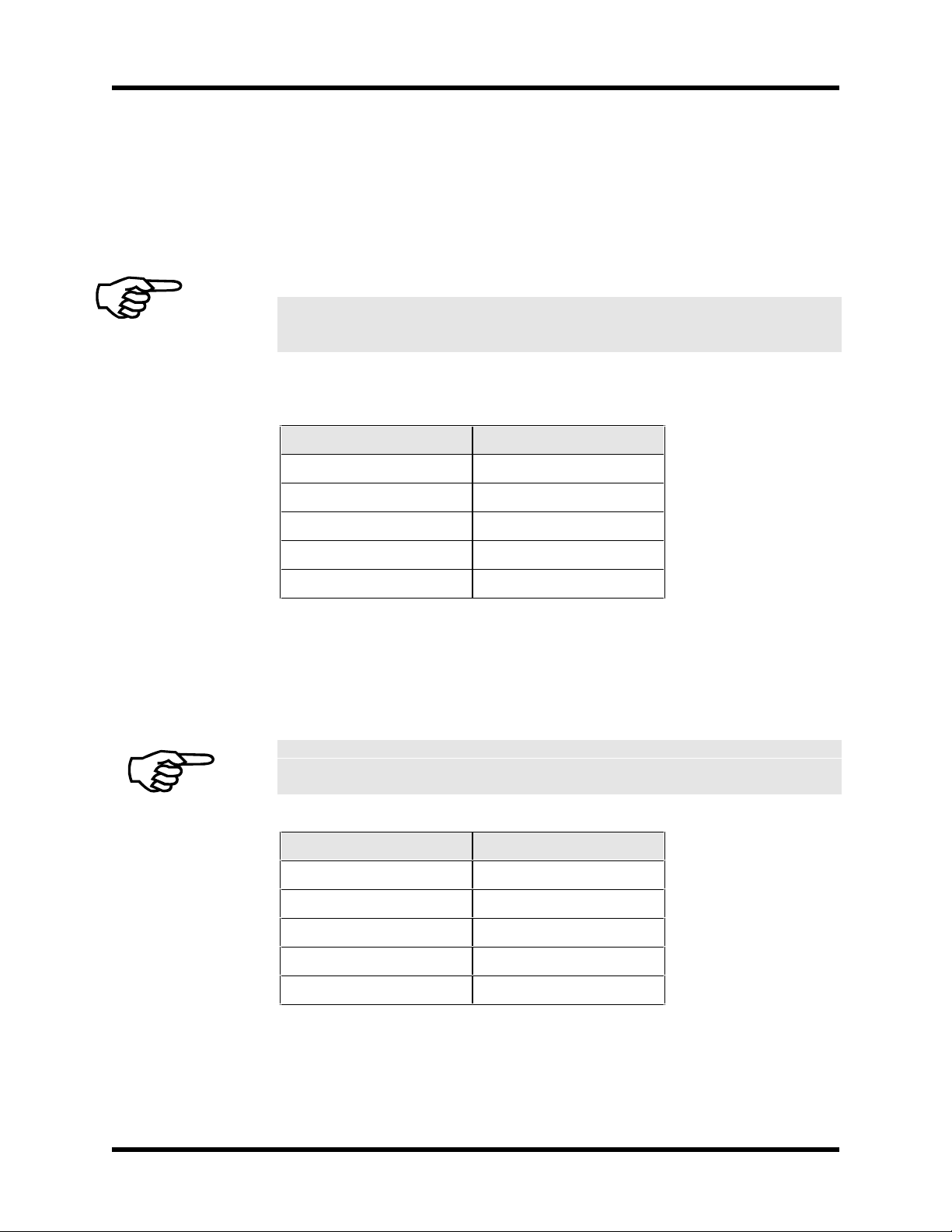
5.2.1.3. Minimizing 50/60 HZ Line Interference
Operating the BAS series amplifiers from an off-line source of 115 VAC or 230 VAC
creates some additional problems.
First, there is a potential problem of EMI generated from the switching power stage of the
BAS amplifier propaga ting through the bridge rectifier and out through the HI and LO
input AC line connections. Back-propagation of noise into the AC lines can b e minimized
using a line filter. An example of such a filter and proper connection to the B AS amplifier
is shown in Figure 5-3.
10A slow blow -BAS10
BAS
AMPLIFIER
FRAME GND
A
C
LO
HI
B
Torque
to 5 - 7 in-lb
.
20A slow blow -BAS20
30A slow blow -BAS30
Use 60 degree C copper conductors only
Schaffner FN2070-10-06
includes common mode
choke and ferrite.
PN: UFM
115/230 VAC
50/60 Hz
Grounding Screw
Earth Ground
This configuration is especially important if the BAS Amplifier is operating at DC bus voltages of 160 VDC or 320 VDC (e.g., 115VAC or 230VAC input power).
Figure 5-3. Back-Propagation Line Filter Connection
Version 1.4 Aerotech, Inc. 5-3
Artisan Technology Group - Quality Instrumentation ... Guaranteed | (888) 88-SOURCE | www.artisantg.com
Technical Details BA SineDrive User’s Manual
Second, another problem that potentially exists with off line connections is 50/60 Hz
electrostatic coupling between the frame of the AC motor and the HI/LO AC input
power. Since LO is referenced to earth ground back at the source, the DC bus of the
amplifier “swings” at 50/60 Hz with respect to the motor frame.
The path of current caused by this coupling between the motor frame and the amplifier
stage passes through the cur rent feedb ack sensing de vices of the amplifier . Depend ing on
the magnitude of this current, a 50/60 Hz torque disturbance may be present in the
position loop.
To eliminate this problem, an isolation transformer can be used to block the 50/60 Hz
from being seen by the motor frame. Refer to Figure 5-4 for connection of this
transformer.
10A slow blow - BAS10
20A slow blow - BAS20
30A slow blow - BAS30
Use 60 degree C copper conductors only
BAS
AMPLIFIER
Torque
to 5 - 7 in-lb
LO
FRAME GND.
This configuration is especially important if the BAS amplifier is operating at DC bus voltages of 160 VDC or 320 VDC
(e.g., 115 VAC or 230 VAC input power).
HI
A
B
C
Grounding Screw
Earth Ground
115/230 VAC
50/60 Hz
Figure 5-4. Isolation Transformer Connection (eliminates torque disturbance)
5.2.2. COM Port
The COM port is a standard 9-pin “D” style connector located on the front of the BAS,
refer to Figure 5-1. It consists of two signal lines; transmit (TXD) and receive (RXD), a
ground, shield, and a 5V power supply line used to power the Aerotech Hand held
Terminal (HHT). Table 5-1 contains the connector pinouts. The BAS is configured as
Data Terminal Equipment (DTE), therefore, a NULL MODEM cable is required to
connect to the PC. This swaps pins 2 and 3 for proper communication.
Table 5-1. COM Port Pinouts
Pins Function
1Shield
2 Receive (RXD)
3 Transmit (TXD)
4,6,7,8 NC
5 Ground (GND)
9+5 V
5-4 Aerotech, Inc. Version 1.4
Artisan Technology Group - Quality Instrumentation ... Guaranteed | (888) 88-SOURCE | www.artisantg.com

BA SineDrive User’s Manual Technical Details
The 5 Volt connection on COM port is for the hand held terminal and is a nonstandard connection.
The baud rate is 9600, no parity, one stop bit.
5.2.3. LED Status Indicators
The BAS contains two LED’s located on the front of the unit that indicate the fault status
of the unit, refer to Figure 5-1. One of the LED’s indicates if power is applied to the unit,
the second indicates the status of the amplifier. A green light indicates the amplifier is in
the ready state and the motor is enabled, while a red light indicates a fault or the power
stage is disabled.
Version 1.4 Aerotech, Inc. 5-5
Artisan Technology Group - Quality Instrumentation ... Guaranteed | (888) 88-SOURCE | www.artisantg.com

Technical Details BA SineDrive User’s Manual
5.3. The I/O Port
The I/O port is a 25-pin “D” style connector that contains all of the general purpose I/O
functions. These include:
• 2 dedicated digital I/O signals (External Enable/Amp Fault)
• and 1 dedicated analog input (INPUT +/-) for the command
The digital I/O are opto-isolated inputs and outputs. One of the two dedicated I/O signals
enables/disables the power stage externally and the second indicates the fault status in the
amplifier.
The analog I/O port can accept a +/- 10 volt differential input. This signal can represent a
current or velocity co mmand fro m anot her controller.
The pinouts for the 25-pin connector are shown in Table 5-2.
To preserve signal integrity and reduce noise, a well-shielded cable must be used to send
the current and velocity commands to the BAS.
Table 5-2. I/O Connector Pinouts (P1)
Pin Function Pin Function
1 Shield 17 Input+
2 CW Limit 18 Input3 CCW Limit 19 Thermistor
4 Home Limit 20 Restore/Reset
5 External Enable 21 SIN
6 Input Common 22 SIN-N
7 MRKR -N 23 COS
8 MRKR 24 COS-N
9 Output Common
10 Fault Out
15, 25 Ground
16 +5V
CW, CCW, MRKR, MRKR-N, SIN, SIN-N, COS, and COS-N are electrically
connected to the same pins on P3. These can be considered outputs.
5.3.1. SIN, SIN-N, COS, COS-N Signals
These signals represent the encoder signals (A, /A, B, /B) from the encoder port. The
encoder feedback is required in either torque or velocity mode in order to perform
sinusoidal commutation in the BAS. The same encoder signals can be split to connect to
the user's position controller to close the position loop. To minimize this effort, the
encoder signals on P3 are connected to P1 on pins 21 to 24 (see Table 5-2).
5-6 Aerotech, Inc. Version 1.4
Artisan Technology Group - Quality Instrumentation ... Guaranteed | (888) 88-SOURCE | www.artisantg.com

BA SineDrive User’s Manual Technical Details
5.3.2. Restore/Reset Signal
This signal can be used to restore the parameters to their default settings during power up.
To restore the parameters, tie this signal to signal common (P1-20 to P1-15) and turn on
power to the unit. The user will be prompted for a course of action to take. After power
up, this signal can be used to reset the BAS.
5.3.3. Input+/Input- Command INPUT
The command input is a signal that represents a ±10V current command or a ±10V
velocity command from an external controller. The input impedance is at least 20K
ohms.
5.3.4. Thermistor Input Signal
A thermistor can be connected to the BAS as a means of detecting a motor over
temperature condition. If over temperature occurs, the BAS aborts motion and shuts
down the power stage. This is a latching condition, (meaning that power must be cycled
to clear the fault). Figure 5-5 shows the circuitry used to detect the over temperature.
While the temperature is low, so is the resistance of the thermistor. Consequently, the
input to the inverter is pulled low and its output is high. As the temperature increases, so
does the thermistor resistance. Once the resistance of the thermistor increases beyond
1.5K Ohms, the input to the inverter will pull high and generate a fault in the controller.
To Thermal
Sensor
+ 5V
5 V Logic Interface
1.5K
74HCT04A
.1UF
Figure 5-5. Over-Temperature Circuitry
Version 1.4 Aerotech, Inc. 5-7
Artisan Technology Group - Quality Instrumentation ... Guaranteed | (888) 88-SOURCE | www.artisantg.com
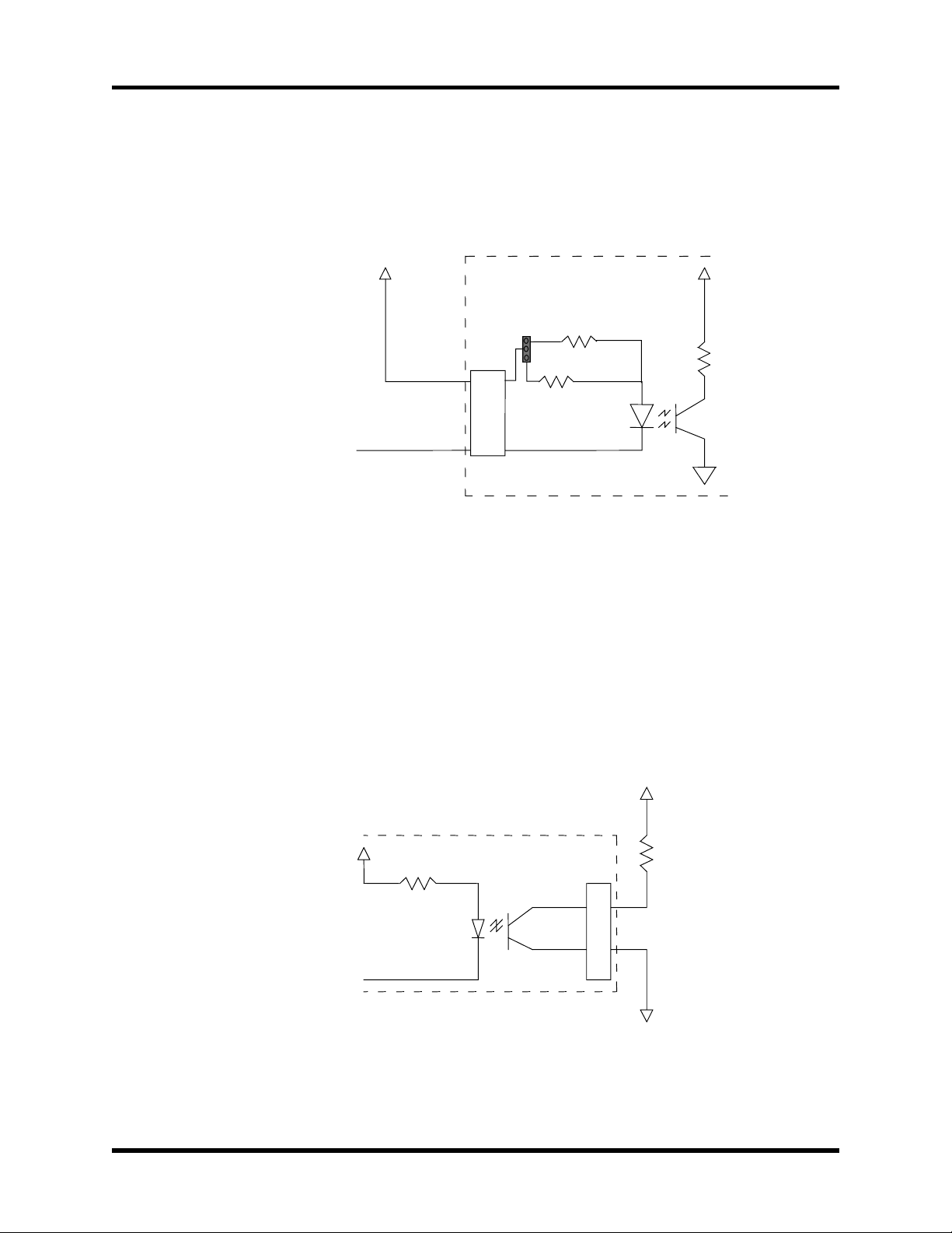
Technical Details BA SineDrive User’s Manual
5.3.5. External Enable Input
The external enable is an opto-isolated input. Figure 5-6 shows the electrical
characteristics of this input.
+5
1.2K
3
JP2
10K OHM
Input Common
Any Opto-Isolated Input
P1
6
5
Opto-Coupler PS2501-4
1
390 OHM
BA SINE DRIVE
Figure 5-6. Electrical Charac t eristics of Opto-Isolated Input
To use an external power supply that is greater than 9 volts, a resistor must be added to
input feed. Place the resistor in series with each input to limit the current to a safe 20mA.
5.3.6. Fault Output
The BAS has a fault output that is opto-isolated. The electrical characteristics of this
output are shown in the Figure 5-7.
+V
BA-SineDrive
R
510 OHM
Opto-Coupler - PS2501 – 4
P1
10
9
ext
Fault Output
Output Common = To
signal common of external
circuit
Figure 5-7. Electrical Characteristics of Opto-Isolated Output
5-8 Aerotech, Inc. Version 1.4
Artisan Technology Group - Quality Instrumentation ... Guaranteed | (888) 88-SOURCE | www.artisantg.com

BA SineDrive User’s Manual Technical Details
V
All digital outputs must operate from the same power supply, since they all reference
the same OUTPUT COMMON (P5-9) .
The following formula calculates the added pull-up resistor value for the external circuitry
Rext > (External Power Supply Volta ge-(Voutput_common+.4))/.02
The maximum external power supply voltage is 80 volts.
EXAMPLE:
Using a 24VDC external supply, find R
−+
24 0 0
=
R
ext
The fault output signal is also an opto-isolated output.
002
.
ext
(.4)
=
1180
.
ohms
5.4. Encoder/Limits/Hall Effects Port
The 25-pin “D” style connector contains all of the necessary feedback inputs to complete
a servo loop. The Hall effect switch inputs are recommended for AC brushless motor
commutation but not required. The pinouts for the connector is shown in Table 5-3.
Table 5-3. Pinouts for the Encoder/Limits/Hall Effects Port
Pin Function Pin Function
1Shield 13 NC
2NC 14 COS
3 Encoder +5 15 COS-N
4 NC 16 Limit +5
5 Hall Effect B 17 SIN
6 Marker-N 18 SIN-N
7 Marker 19 Tach+
8 Tach- 20 Limit Com.
9 NC 21 Encoder Com.
10 Hall Effect A 22 Home Limit-N
11 Hall Effect C 23, 25 NC
12 CW Limit 24 CCW Limit
Version 1.4 Aerotech, Inc. 5-9
Artisan Technology Group - Quality Instrumentation ... Guaranteed | (888) 88-SOURCE | www.artisantg.com
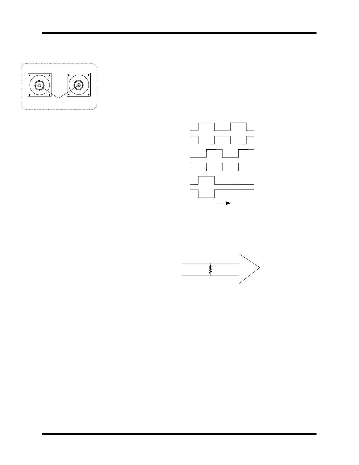
Technical Details BA SineDrive User’s Manual
Motor Mounting
Plate (Front View)
CW Rotation
(Positive Direction)
Motor Shaft
Motor Mounting
Plate (Front View)
CCW Rotation
(Negative Direction)
5.4.1. Encoder Interface
The encoder interface requires square wave signals from a line driver differential output
encoder. Figure 5-8 illustrates the encoder phasing with relation to motor rotation.
Additionally, as part of each encoder interface, there are inputs for marker signals that are
received by a differential input comparator circuit. These signals are standard on
incremental encoders. The theoretical max encoder input frequency is 2.5 MHz. The
minimum edge separation is 1/10 MHz.
COS
COS-N
SIN
SIN-N
MKR
MKR-N
Figure 5-8. CW Motor Rotation (Viewed from the Mounting Flange End)
The encoder signals are terminated with 180 ohm resisters, refer to Figure 5-9.
Consequently, the encoder must be able to drive the BAS and external controller encoder
interface.
SIN , C O S
180
SIN-N, COS-N
SN75157
Figure 5-9. Encoder Input Circuit
5.4.2. Hall Effect Interface
The Hall effect switches form a digital representation of the motor phasing that the
microprocessor uses to commutate the motor. This digital representation comprises three
5 volt signals that form a digital six step pattern. The controller receives these signals with
a circuit that is electrically identical to the limit input circuit. Refer to Figure 5-10 for Hall
effect input circuitry.
5-10 Aerotech, Inc. Version 1.4
Artisan Technology Group - Quality Instrumentation ... Guaranteed | (888) 88-SOURCE | www.artisantg.com

BA SineDrive User’s Manual Technical Details
HALL A
HALL B
HALL C
P3
10 K (x3)
10 K
.01uF
10K
.01uF
10K
.01uF
S1
Figure 5-10. Hall Effect Input Circuit
Aerotech brushless rotary motors are shipped from the factory with the correct motor
phase to Hall effect device relationship established. This is essential for proper motor
commutation. The parameter that affects this relationship is PRM:11 and is set at 0,
Figure 5-11 and Figure 5-12 illustrates the proper Hall effect and motor phasing for both
CW and CCW motor rotation (viewed looking into the mounting flange of the motor).
During CW motor rotation each Hall effect signal is at a logic low state when its
corresponding motor phase is at a positive voltage. During CCW rotation each Hall effect
signal is at a logic high state when its corresponding motor phase is at a positive voltage.
Hall Effect A Hall Effect A
Hall Effect B Hall Effect B
Hall Effect C Hall Effect C
Motor Phase A Motor Phase A
Motor Phase B Motor Phase B
Motor Phase C Motor Phase C
CW Motor Rotation CCW Motor Rotation
Figure 5-11. Hall Effect Motor Phasing
Version 1.4 Aerotech, Inc. 5-11
Artisan Technology Group - Quality Instrumentation ... Guaranteed | (888) 88-SOURCE | www.artisantg.com
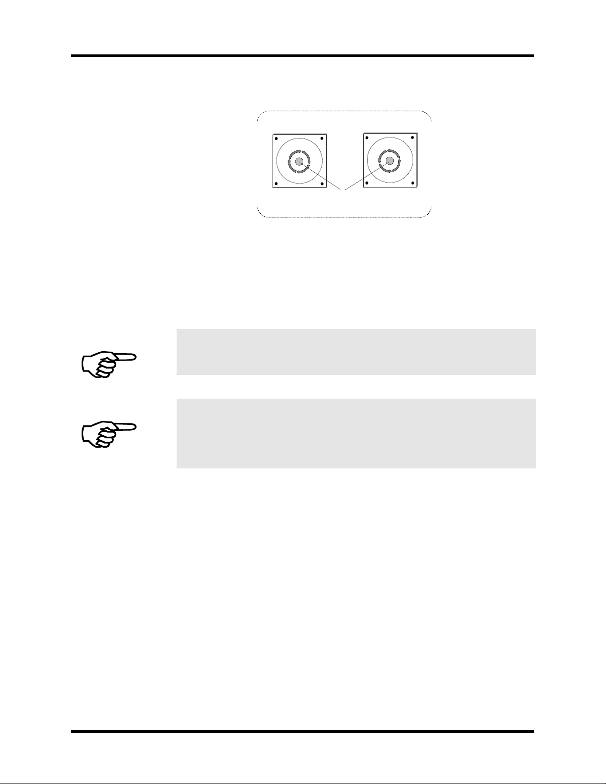
Technical Details BA SineDrive User’s Manual
Motor Mounting
Plate (Front View)
CW Rotation
(Positive Direction)
Motor Shaft
Motor Mounting
Plate (Front View)
CCW Rotation
(Negative Direction)
Figure 5-12. Motor Rotation (From Mounting Flange End)
The waveforms created by the motor phasing can be observed using a wye resistor
network, a dual trace oscilloscope, and performing the following steps.
The following procedure is only necessary if the user has to replace a defective
encoder or is using a non-Aerotech motor.
Motor voltage is monitored without power applied to the motor.
Before performing the following steps, remove all connections to the motor except
the wye resistor network. Remove all mechanical connections to the motor shaft.
1. Connect the ends of three resistors to motor terminals A, B, C. Refer to
Figure 5-13.
2. Use one channel of the oscilloscope to monitor motor terminal A with
respect to the “Wye” neutral (the point where all resistors are connected
together), refer to Figure 5-13.
3. Connect a 5V power supply to the power pins of the encoder, refer to
Figure 5-14.
4. Connect the second channel of the oscilloscope to Hall effect A on the
encoder.
5. Once the oscilloscope is connected with one probe monitoring a motor
phase and the other monitoring a Hall effect signal, rotate the motor by hand
using the motor shaft. The motor will generate a voltage upon rotation.
6. Observe the phase relationship of the motor phase to the Hall effect signal.
5-12 Aerotech, Inc. Version 1.4
Artisan Technology Group - Quality Instrumentation ... Guaranteed | (888) 88-SOURCE | www.artisantg.com

BA SineDrive User’s Manual Technical Details
It is necessary for the voltage generated by the motor phase A to be in phase with
signal used as Hall effect A, refer to Figure 5-11.
7. Move the probe on the Hall effect line to the other two Hall effect lines,
observing their phase relationship to the motor voltage.
8. Repeat this process for the other two motor phases
Using this procedure, connect the Hall effect signals with the appropriate motor phases as
shown in Figure 5-7.
10K
10K
PSUEDO NEUTRAL
10K
TO MOTOR PHASE A
TO MOTOR PHASE B
TO MOTOR PHASE C
Figure 5-13. Motor Phase Voltage Observation Scheme
+5V
Hall Effect A, B, and
C,encoder connector.
O-Scope
Probe
Figure 5-14. Encoder Phase Voltage Observation Scheme
Version 1.4 Aerotech, Inc. 5-13
Artisan Technology Group - Quality Instrumentation ... Guaranteed | (888) 88-SOURCE | www.artisantg.com

Technical Details BA SineDrive User’s Manual
5.5. Servo Amplifier Specifications
The electrical and controller specifications for all BAS drive models are listed in
Table 5-4.
Table 5-4. Electrical Specifications
Model Units BAS10 BAS20 BAS30 BAS50 BAS75 BAS100
Output Voltage
(1)
VDC 40 to 320
(2)
Peak Output Current A
Continuous Output Current A
Peak Power Output Watts 2,720 5,440 8,160 13,600 20,130 28,800
Continuous Power Output Watts 1,360 2,720 4,080 6,800 10,080 14,400
Power Amplifier Bandwidth kHz 2
PWM Switching Frequency kHz 20
Minimum Load Inductance mH .8 @ 160 VDC (1 mH @ 320 VDC)
Operating Temperature
Storage Temperature
Weight kg (lb) 1.1 (2.5) 3.9 (8.5) 5.6 (12.3) 6.5 (14.2)
Maximum Shunt Regulator
Dissipation
Brushless Operation Torque (current), Velocity
Power Input Single Phase AC line input
Commutation Sinusoidal from Encoder
Encoder Input Frequency 20 MHz maximum input frequency (after quadrature), RS-422 differential line driver
Indicators Drive enable LED, Power-On LED
1
Depends on AC input voltage.
2
40-80 VDC bus requires external transformer, 110 VAC auxiliary input for control input power.
(peak)
(peak)
deg C°
deg C°
Watts 40 (Optional) 40 (Optional) 40 100 (10A Ext.)
10 20 30 50 75 100
5 1015253750
0 to 50
-30 to 85
28-230 VAC, 50-60 Hz
28-230 VAC, 50-60 Hz
1- 3 Phase
5-14 Aerotech, Inc. Version 1.4
Artisan Technology Group - Quality Instrumentation ... Guaranteed | (888) 88-SOURCE | www.artisantg.com

BA SineDrive User’s Manual Technical Details
5.6. BAS Amplifier Dimensions
The outline dimensions for the BAS amplifiers are shown in Figure 5-15 and Figure 5-16.
25.4 [1.00]
Typ.
A
B
C
BA
SINEDRIVE
ACTIVE
ENABLE
P1
I/O
AEROTECH, INC.
PITTSBURGH, PA USA
P/N -
S/N -
AEROTECH
P2
COMM.
AC POWER
COMPONENTS
DIVISION
31.8 [1.25]
®
DRIVE
P3
ENC
Typ.
177.8 [7.00]
Typ.
127.0 [5.00]
6.4 [.25]
Typ.
169.4 [6.67]
186.7 [7.35]
73.8 [2.91]
4.8 [.19]
Typ.
4.4 [.17]
Typ.
Dimensions - Millime ters [Inches]
132.6 [5.22]
Typ.
82.0 [3.23]
Typ.
12.7 [.50]
Typ.
Figure 5-15. BAS Amplifier Dimensions (10/20/30)
Version 1.4 Aerotech, Inc. 5-15
Artisan Technology Group - Quality Instrumentation ... Guaranteed | (888) 88-SOURCE | www.artisantg.com

Technical Details BA SineDrive User’s Manual
7.1 [.28]
168.1 [6.62]
117.4 [4.62]
Sq.
11.7 [.46]
17.5 [.69]
217.9 [8.58]
182.9 [7.20]
BAS75
33.3 [1.31]
181.2 [7.13]
BAS100
AUXILIARY
PWR INPUT
HI
LO
G
1
2
EXT S HUNT
DANGER!
HIGH VOLTAGE
SINEDRIVE
ACTIVE
ENAB LE
P1 P2 P3
I/O COM ENC
128.6 [5.06]
BAS75
92.7 [3.65]
PWR INPUT
AC1
AC2
AC3
G
A
MTR B
C
G
BA
AEROTECH ®
DRIVE
COMPONENTS
DIVISION
95.3 [3.75]
BAS50
2.5 [.10]
231.4 [9.11]
241.3 [9.50]
Typ.
77.7 [3.06]
213.4 [8.40]
49.6 [1.95]
20.0 [.79]
38.0 [1.49]
10.7 [.42]
64.8 [2.55]
12.7 [a.50]
13.5 [.53]
163.5 [6.44]
206.8 [8.14]
9.4 [.37]
5.5 [.22]
Typ.
2.3 [.09]
AEROTECH, INC.
PITTSBURGH, PA USA
P/N
S/N
152.4 [6.00]
Typ.
28.6 [1.12]
Typ.
BAS100
24.1 [.95]
Typ.
85.9 [3.38]
50.8 [2.00]
Typ.
Dimensions - Millimeters [Inches]
Figure 5-16. BAS Amplifier Dimensions (50/75/100)
5-16 Aerotech, Inc. Version 1.4
Artisan Technology Group - Quality Instrumentation ... Guaranteed | (888) 88-SOURCE | www.artisantg.com

BA SineDrive User’s Manual Technical Details
5.6.1. Mounting Procedures for the BAS 10/20/30/50
To ensure proper heat dissipation, Aerotech recommends the following procedures.
1. Use the mounting procedure shown in Figure 5-18. The wider part of the amp should
be mounted to the heat sink.
2. Heat sink should be at least 2 feet
2
x0.25 inch thick minimum.
3. The heat sink should be free of paint or any other thermal
barrier.
4. The heat sink must be flat to allow good thermal conductivity between the heat sink
and the amplifier.
5. If possible, add a thermal conductivity enhancer (i.e., thermal grease between the
heat sink and the amplifier).
6. Adding an external fan will remove a considerable amount of heat from the heat sink
and allow the amplifier to operate at a much cooler temperature.
IW
0.35
IW
4.5
3.23 0.78
0.50
.18
7.00 0.18
7.35
Heat Sink
Figure 5-17. BAS Amp Top View (Preferred Mounting, 10/20/30/50)
Version 1.4 Aerotech, Inc. 5-17
Artisan Technology Group - Quality Instrumentation ... Guaranteed | (888) 88-SOURCE | www.artisantg.com

Technical Details BA SineDrive User’s Manual
It is advisable that the amplifier be mounted lying flat on a metal panel not less than
two square feet for better heat dissipation. Refer to Figure 5-18.
®
DRIVE
P3
ENC
DIVISION
COMPONENTS
AC POWER
C
A
B
SINEDRIVE
AEROTECH
P2
COMM.
AEROTECH, INC.
PITTSBURGH, PA USA
P/N -
ACTIVE
ENABLE
P1
I/O
S/N -
BA
Metal Panel
Preferred mounting for better heat dissipation.
Figure 5-18. Preferred Mounting of BAS Amplifiers (10/20/30/50)
5.6.2. Mounting Procedures for the BAS 75/100
To ensure proper heat dissipation, Aerotech recommends the following procedures.
1. Use the mounting procedure shown in Figure 5-19. The wider part of the amp should
be mounted to the heat sink.
2. Heat sink should be at least 2 feet
3. The heat sink should be free of paint or any other thermal
4. The heat sink must be flat to allow good thermal conductivity between the heat sink
and the amplifier.
5. If possible, add a thermal conductivity enhancer (i.e., thermal grease between the
heat sink and the amplifier).
6. Adding an external fan (already included in the BAS 100) will remove a considerable
amount of heat from the heat sink and allow the amplifier to operate at a much cooler
temperature.
2
x0.25 inch thick minimum.
barrier.
5-18 Aerotech, Inc. Version 1.4
Artisan Technology Group - Quality Instrumentation ... Guaranteed | (888) 88-SOURCE | www.artisantg.com

BA SineDrive User’s Manual Technical Details
BAS100
BAS75
AUXILIARY
PWR INPUT
HI
LO
G
1
2
EXT SHUNT
DANGER!
HIGH VOLTAG E
PW R INPUT
AC1
AC2
AC3
G
A
MTR B
C
G
BA
SINEDRIVE
ACTIVE
ENABLE
P1 P2 P3
I/O COM ENC
AEROTECH
DRIVE
COMPONENTS
AEROTECH, INC.
PITTSBURGH, PA USA
P/N
S/N
®
DIVISION
Metal Panel
(Preferred mounting for better heat dissipation)
Figure 5-19. Preferred Mounting of BAS Amplifiers (75/100)
∇ ∇ ∇
Version 1.4 Aerotech, Inc. 5-19
Artisan Technology Group - Quality Instrumentation ... Guaranteed | (888) 88-SOURCE | www.artisantg.com

Technical Details BA SineDrive User’s Manual
5-20 Aerotech, Inc. Version 1.4
Artisan Technology Group - Quality Instrumentation ... Guaranteed | (888) 88-SOURCE | www.artisantg.com

BA SineDrive User’s Manual Troubleshooting
CHAPTER 6: TROUBLESHOOTING
In This Section:
• Amplifier Related Problems .........................6-1
6.1. Amplifier Related Problems
This section covers symptoms, probable causes, and solutions related to the BAS
amplifier operation. Table 6-1 lists the most common symptoms of irregular operation
and the possible causes and solutions for these faults.
Before performing the tests described in Table 6-1, be aware that lethal voltages exist
on the amplifier’s PC board and at the input and output power connections. A
qualified service technician or electrician should perform these tests.
DANGER
Table 6-1. Amplifier Faults, Causes, and Solutions
Symptom Possible Cause and Solution
Receive a "BAS not conn ected" error
when the MMI software loads.
Receive an "Error Loading from File"
error when attempting to open the
parameters screen.
1. The BAS is not on. Turn on the BAS, and click the button.
If this does not work, exit and restart the BAS.
2. The BAS is not connected to the COM port. Check to be sure the proper COM
port is selected in the MMI software and the BAS is connected to it.
3. There is a conflict with the current COM port. If there is a conflict with the
selected COM port, the software automatically switches to a COM port it can
open. Try moving the BAS connection to another COM port and restart the MMI
software.
4. The communications parameters do no t match between the MM I interface and the
BAS, because either the MMI software was just installed or th e BAS’s firmware
was upgraded. Enter the MM I interface by clicking YES to close t he COM port.
Select communications parameters to match the BAS settings from the menu and
press the reset button. Then select Connect from the Communications menu.
5. The BAS is not in the proper mode (Local vs. Remote mode). To insure the BAS
is in remote mode, open the COM_BAI DOS software and press the space bar. If
the text appears, the BAS is in the wrong mode.
6. No COM port can be found (both COM1 and COM2 are in use). Close the BAS
MMI and find the conflict on the port the BAS is attached to.
1. There is problem with the system registry. Run REG95.BAT or REGNT.BAT file
that are included in the installation. For more information, refer to the
README.TXT file.
Version 1.4 Aerotech, Inc. 6-1
Artisan Technology Group - Quality Instrumentation ... Guaranteed | (888) 88-SOURCE | www.artisantg.com

Troubleshooting BA SineDrive User’s Manual
Table 6-1. Amplifier Faults, Causes, and Solutions (Continued)
Symptom Possible Ca use and Solution
Nothing appears in the
window when starting the
COM_BAS.exe or when
using the Hand held
Terminal (HT).
Receive "RMS current"
error every time trying to
move the motor.
When I connect the serial
cable to the unit, the PC
freezes.
The amplifier will not
enable.
1. The BAS is sitting idle waiting for a keystroke. Press the space bar and observe if anythin g
appears. If it does, the unit is fine, if it does not; it may be in remote mode.
2. The BAS is in remote mode. Press CNTRL-A and wait for text to appear. If it does, proceed
to use the unit normally.
3. The BAS is not communicating correctly due to the firmware being damaged. Try
reinstalling the firmware using the UPGRADE.EXE software (included with both the
COM_BAS.exe and MMI software packages). If this does not work, the unit needs to be
bootstrapped. For more information, contact Aerotech.
1. The gains are set too high. Try turning down the values Kp, and Ki.
2. There are offsets in the D/A converters. Adjusting parameters 13 and 14 can help null out
these offsets, however, it is a precarious process. For additional help, contact Aerotech.
1. Problem with the serial cable. Make sure that a null modem cable is being used and the
cable is intact. Ensure the cable is wired properly. See Section 1.5.4. for correct pinouts.
1. The external enable line is disabling the amplifier. If an external enable line is not being
used, check to be sure t hat the external enable polarity is set to low (PRM:22 = 0).
2. The thermistor is disabling the amplifier. Check to be sure the correct polarity is being used
for the thermistor (PRM:21).
3. There is a hardware problem on the amplifier. Reset the BAS and observe if the Enable
LED blinks and/or the stage jumps before the amplifier disables. If it does, the problem is
likely phasing or tuning. If it does not, either the thermistor or the external enable line is
pulled, or there is problem with the BAS.
∇ ∇ ∇
6-2 Aerotech, Inc. Version 1.4
Artisan Technology Group - Quality Instrumentation ... Guaranteed | (888) 88-SOURCE | www.artisantg.com

Warranty and Field Service BA SineDrive User’s Manual
APPENDIX A: WARRANTY AND FIELD SERVICE
In This Section:
• Laser Products.......................................................... A-1
• Return Procedure...................................................... A-1
• Returned Product Warranty Determination.............. A-2
• Returned Product Non-warranty Determination....... A-2
• Rush Service............................................................. A-2
• On-site Warranty Repair .......................................... A-2
• On-site Non-warranty Repair................................... A-2
Aerotech, Inc. warrants its products to be free from defects caused by faulty materials or
poor workmanship for a minimum period of one year from date of shipment from
Aerotech. Aerotech’s liability is limited to replacing, repairing or issuing credit, at its
option, for any products which are returned by the original purchaser during the warranty
period. Aerotech makes no warranty that its products are fit for the use or purpose to
which they may be put by the buyer, whether or not such use or purpose has been
disclosed to Aerotech in specifications or drawings previously or subsequently pr ovided,
or whether or not Aerotech’s products are specifically designed and/or manufactured for
buyer’s use or purpose. Aerotech’s liability or any claim for loss or damage arising out of
the sale, resale or use of any of its products shall in no event exceed the selling price of
the unit.
Aerotech, Inc. warrants its laser products to the original purchaser for a minimum period
of one year from date of shipment. This warranty covers defects in workmanship and
material and is voided for all laser power supplies, plasma tubes and laser systems subject
to electrical o r physical abuse, ta mpering (such as op ening the housing or r emoval of the
serial tag) or improper operation as determined by Aerotech. This warranty is also voided
for failure to comply with Aerotech’s return procedures.
Claims for shipment damage (evident or concealed) must be filed with the carrier by the
buyer. Aerotech must be notified within (30) days of shipment of incorrect materials. No
product may be returned, whether in warranty or out of warranty, without first obtaining
approval from Aerotech. No credit will be given nor repairs made for products returned
without such approval. Any returned product(s) must be accompanied by a return
authorization number. The return authorization number may be obtained by calling an
Aerotech service center. Products must be returned, prepaid, to an Aerotech service
center (no C.O.D. or Collect Freight accepted). The status of any product returned later
than (30) days after the issuance of a return authorization number will be subject to
review.
After Aerotech’s examination, warranty or out-of-warranty status will be determined. If
upon Aerotech’s examination a warranted defect exists, then the product(s) will be
repaired at no charge and shipped, prepaid, back to the buyer. If the buyer desires an air
freight return, the product(s) will be shipped collect. W arranty repairs do no t extend the
original warranty period.
Laser Products
Return Procedure
Returned Product
Warranty Determination
Version 1.4 Aerotech, Inc.A-1
Artisan Technology Group - Quality Instrumentation ... Guaranteed | (888) 88-SOURCE | www.artisantg.com

BA SineDrive User’s Manual Warranty and Field Service
Returned Product Non-
warranty Determination
Rush Service
On-site Warranty Repair
After Aerotech’s examination, the buyer shall be notified of the repair cost. At such time
the buyer must issue a valid purchase order to cover the cost of the repair and freight, or
authorize the product(s) to be shipped back as is, at the buyer’s expense. Failure to obtain
a purchase order number or approval within (30) days of notification will result in the
product(s) being returned as is, at the buyer’s expense. Repair work is warranted for (90)
days from date of shipment. Replacement components are warranted for one year from
date of shipment.
At times, the buyer may desire to expedite a repair. Regardless of warranty or out-ofwarranty status, the buyer must issue a valid purchase order to cover the added rush
service cost. Rush service is subject to Aerotech’s approval.
If an Aerotech product cannot be made functional by telephone assistance or by sending
and having the customer install replacement parts, and cannot be returned to the Aerotech
service center for repair, and if Aerotech determines the problem could be warrantyrelated, then the following policy applies:
Aerotech will provide an on-site field service representative in a reasonable amount of
time, provided that the customer issues a valid purchase order to Aerotech covering all
transportation and subsistence costs. For warranty field repairs, the customer will not b e
charged for the cost of labor and material. If service is rendered at times other than
normal work periods, then special service rates apply.
If during the on-site repair it is determined the problem is not warranty related, then the
terms and conditions stated in the following "On-Site Non-Warranty Repair" section
apply.
On-site Non-warranty
Repair
Company Address
If any Aerotech product cannot be made functional by telephone assistance or purchased
replacement parts, and cannot be returned to the Aerotech service center for repair, then
the following field service policy applies:
Aerotech will provide an on-site field service representative in a reasonable amount of
time, provided that the customer issues a valid purchase order to Aerotech covering all
transportation and subsistence costs and the prevailing lab or cost, including travel time,
necessary to complete the repair.
Aerotech, Inc. Phone: (412) 963-7470
101 Zeta Drive Fax: (412) 963-7459
Pittsburgh, PA 15238-2897
USA
∇ ∇ ∇
A-2 Aerotech, Inc. Version 1.4
Artisan Technology Group - Quality Instrumentation ... Guaranteed | (888) 88-SOURCE | www.artisantg.com

BA SineDrive User’s Manual Index
Enable Polarity, 3-13
Symbols
+5V Too Low, 2-7
A
Abort, 2-7
Amplifier Faults, 6-1
Amplifier Related Problems, 6-1
Analog I/O, 5-6
B
BAS Software, 1-3
Interface, 1-3
Bias Supply Too Low, 2-7
Bit Patterns, 2-5
Brushless DC Motor, 2-1
C
Capacitive Coupling, 5-2
C-Change Parameter, 2-3
Change Parameter, 2-3
COM Port, 1-12, 5-4
Communications Mode, 2-2
Commutation Card, 1-2
Connector, 1-6, 5-1
COS signal, 5-6
COS-N signal, 5-6
CTRL-D, 2-7
Current Command, 1-2
Current mode, 4-1
Current Mode, 4-1
Current Offset Adjustment, 3-8
D
DC Bus Over-Voltage, 2-7
D-Display Tracking, 2-4
Digital I/O, 5-6
Dimensions
BAS 10/20/30, 5-15
BAS 50/75/100, 5-16
Display Tracking, 2-4
Download Parameters, 2-7
E
E-Display Error Messages, 2-6
Electrical Cycles, 3-4
Electrical Specifications, 5-14
Electronic Tach, 3-2
EMI Interference, 5-2
Encoder Fault, 2-7
Encoder Interface, 5-10
Encoder Phase Voltage Observation Scheme, 5-13
Encoder Polarity, 3-13
Encoder Resolution, 3-3
Encoder/Limits/Hall Effects Port, 5-9
Error Message
AMP Fault, 2-7
Error Messages, 2-6
F
Fault Conditions, 2-6
Fault Output, 5-8
Fault Output Polarity, 3-13
Faults
Encoder not present, 2-7
How to clear, 2-7
Max allowable velocity error, 2-6
RMS current error, 2-6
Temperature too high, 2-7
Thermistor fault, 2-7
Two invalid hall states, 2-6
Field Service Po licy, A-1
Filter Cutoff, 3-7
Fusing
BAS 10/20/30, 1-9
BAS 50/75/100, 1-10
G
Grounding Techniques, 5-2
H
Hall Effect Input Circuit, 5-11
Hall Effect Interface, 5-10
Hall Effects Available, 3-4
Hardware function, 1-6, 5-1
Hardware overview, 1-6, 5-1
Help, 1-4
I
I/O Connector Pinouts, 5-6
I/O Port, 5-6
Initialization Current, 3-5
Input Command Offset, 3-8
Input Power, 1-10
Input Signal, 1-2
Input+/Input- Signals, 5-7
Inrush Limiting
BAS 10/20/30, 1-9
BAS 50/75/100, 1-10
Integral Clamp, 3-11
Version 1.4 Aerotech, Inc. i
Artisan Technology Group - Quality Instrumentation ... Guaranteed | (888) 88-SOURCE | www.artisantg.com

Index
BA SineDrive User’s Manual
Integral Velocity Gain, 3-2
Invalid Hall States, 2-6
Invalid Signals, 2-7
Isolation transformer, 5-4
J
JP2, 2-1
Jumper
Configuration, 2-1
Selections, 2-1
L
LED indicator, 1-6
LED Indicator, 5-1
LED status indicators, 1-12
LED Status Indicators, 5-5
Limits, 5-9
Line Filter Connection, 5-3
Line Interference, 5-3
Low Pass Filter, 3-6
M
Mechanical Drawings, 5-15
Menu Commands, 2-3
MMI, 1-3, 1-4
Motor Connections, 5-2
BAS 50/75/100, 1-10
Motor Phase Voltage Observation Scheme, 5-13
Motor Phasing, 5-10, 5-11
Motor Rotation, 5-12
Mounting Procedures
BAS 10/20/30/50, 5-17
BAS 75/100, 5-18
N
Next menu, 2-7
Noise
Back-Propagation, 5-3
O
Online Help, 1-4
Operating Mode, 3-11
Opto-Isolated Inputs, 5-8
Opto-Isolated Outputs, 5-8
Output Short Circuit, 2-7
Over-temperature, 2-7
Over-Temperature Circuitry, 5-7
P
P3, 5-6
P5, 5-9
Parameter Range, 1-4
Parameters, 3-1
Purpose of, 1-5
Restore/Reset, 5-7
Transfer, 2-7
Units of, 1-5
Viewing the maximum and minimum, 1-4
Parameters Screen, 2-2
Phase Offset, 3-7
Phasing, 3-7
PID Control Loop, 3-1
Power connections, 1-6
Power Connections, 5-1, 5-2
BAS 10/20/30, 1-7
BAS 50/75/100, 1-8
Precautions, 1-13
Previous menu, 2-7
PRM
1, 3-2, 4-2
10, 3-7
11, 3-7, 4-1
12, 3-8, 4-2
13, 3-8
14, 3-8
15, 3-9
16, 2-6, 3-9
17, 2-6, 3-10
18, 2-6, 3-10
19, 3-11
2, 3-2, 4-2
20, 3-11, 4-1, 4-2
21, 2-7, 3-12
22, 3-13, 4-1
23, 3-13
24, 3-13
3, 3-2, 4-2
4, 3-3, 4-1
5, 3-4
6, 3-4, 3-5
7, 3-4, 3-5
8, 3-6
9, 3-6, 4-1
Product Overview, 1-1
Proportional Velocity Gain, 3-2
Pulse Width Modulation, 1-1
R
Reset, 2-7
Restore/Reset Signals, 5-7
RMS Current, 2-7
RMS Fault Threshold, 2-6
RS232 Interface, 1-2
P1, 5-6
ii Aerotech, Inc. Version 1.4
Artisan Technology Group - Quality Instrumentation ... Guaranteed | (888) 88-SOURCE | www.artisantg.com

BA SineDrive User’s Manual Index
S
Safety Procedures, 1-13
Servo Loop Parameter, 3-1
Servo Peak Current Limit, 3-9
Servo RMS Current Timeout, 3-10
Servo RMS Limit, 3-9
Servo Update Rate, 3-6
Servo Velocity Trap, 3-10
Shielding Techniques, 5-2
SIN signal, 5-6
SIN-N signal, 5-6
Software, 1-3
Interface, 1-3
Space Bar, 2-7
T
Technical details, 5-1
Thermistor Input Signal, 5-7
Thermistor Polarity, 3-12
Torque Command, 1-2
Tracking, 2-5
Tracking Screen, 2-2
Transfer Parameters, 2-7
Troubleshooting, 0-1
T-Transfer Parameters, 2-7
Tuning, 4-2
U
Upload Parameters, 2-7
User Selectable Jumper
Control Board, 2-1
Power Board, 2-1
V
Velocity Command, 1-2
Velocity Error, 2-6
Velocity Mode, 4-1, 4-2
Viewing the maximum and minimum parameters, 1 -4
Volt Options, 1-11
W
Warnings, 1-13
Warranty Policy, A-1
Wiring Techniques, 5-2
∇ ∇ ∇
Version 1.4 Aerotech, Inc. iii
Artisan Technology Group - Quality Instrumentation ... Guaranteed | (888) 88-SOURCE | www.artisantg.com

Index
BA SineDrive User’s Manual
iv Aerotech, Inc. Version 1.4
Artisan Technology Group - Quality Instrumentation ... Guaranteed | (888) 88-SOURCE | www.artisantg.com

READER’S COMMENTS
AEROTECH
R
BA-SineDrive User’s Manual
P/N EDU164, November, 2000
Please answer the questions below and add any suggestions for improving this document. Is the
information:
Yes No
Adequate to the subject? ____ ____
Well organized? ____ ____
Clearly presented? ____ ____
Well illustrated? ____ ____
Would you like to see more illustrations? ____ ____
Would you like to see more text? ____ ____
How do you use this document in your job? Does it meet your needs?
What improvements, if any, would you like to see? Please be specific or cite examples.
_____________________________________________________________________
_____________________________________________________________________
_____________________________________________________________________
_____________________________________________________________________
_____________________________________________________________________
_____________________________________________________________________
Your name ________________
Your title ________________
Company name ________________
Address ________________
________________
Remove this page from the document and fax or mail your comments to the technical writing
department of Aerotech.
AEROTECH, INC.
Technical Writing Department
101 Zeta Drive
Pittsburgh, PA. 15238-2897 U.S.A.
Fax number (412) 967-6870
Artisan Technology Group - Quality Instrumentation ... Guaranteed | (888) 88-SOURCE | www.artisantg.com

Artisan Technology Group - Quality Instrumentation ... Guaranteed | (888) 88-SOURCE | www.artisantg.com

Artisan Technology Group is your source for quality
new and certied-used/pre-owned equipment
• FAST SHIPPING AND
DELIVERY
• TENS OF THOUSANDS OF
IN-STOCK ITEMS
• EQUIPMENT DEMOS
• HUNDREDS OF
MANUFACTURERS
SUPPORTED
• LEASING/MONTHLY
RENTALS
• ITAR CERTIFIED
SECURE ASSET SOLUTIONS
SERVICE CENTER REPAIRS
Experienced engineers and technicians on staff
at our full-service, in-house repair center
Instra
Remotely inspect equipment before purchasing with
our interactive website at www.instraview.com
Contact us: (888) 88-SOURCE | sales@artisantg.com | www.artisantg.com
SM
REMOTE INSPECTION
View
WE BUY USED EQUIPMENT
Sell your excess, underutilized, and idle used equipment
We also offer credit for buy-backs and trade-ins
www.artisantg.com/WeBuyEquipment
LOOKING FOR MORE INFORMATION?
Visit us on the web at www.artisantg.com for more
information on price quotations, drivers, technical
specications, manuals, and documentation
 Loading...