

Page 1

T15e Tag
Deployment & User Guide
0981-587-000 REV A
Published: 2019/06/20
Page 2
WARNING!
Disclaimer
Trademark Acknowledgements
To comply with FCC and IC RF exposure compliance requirements, the device should be located at a distance of at
least 20 cm from all persons during normal operation. The antennas used for this product must not be co-located
or operated in conjunction with any other antenna or transmitter.
Le dispositif doit être placé à une distance d'au moins 20 cm à partir de toutes les personnes au cours de son fonctionnement
normal. Les antennes utilisées pour ce produit ne doivent pas être situés ou exploités conjointement avec une autre antenne
ou transmetteur.
The information and know-how included in this document are the exclusive property of STANLEY Healthcare and are
intended for the use of the addressee or the user alone. The addressees shall not forward to another their right of using
the information, know-how or document forwarded herewith, in whole or in part in all matters relating or stemming from or
involved therein, whether for consideration or without consideration, and shall not permit any third party to utilize the
information, know-how or the documents forwarded herewith or copies or duplicates thereof, unless at the company’s
consent in advance and in writing. Any distribution, advertisement, copying or duplication in any form whatsoever is
absolutely prohibited. The Company reserves the right to sue the addressee, user and/or any one on their behalves, as
well as third parties, in respect to breaching its rights pertaining to the intellectual rights in particular and its rights of
whatever kind or type in the information, know-how or the documents forwarded by them herewith in general, whether by
act or by omission.
This document is confidential and proprietary to STANLEY Healthcare and is not to be distributed to any persons other
than licensed AeroScout Visibility System users or other persons appointed in writing by STANLEY Healthcare.
AeroScout is a trademark of Stanley Black & Decker, Inc. or its affiliates. Other brand products and service names are
trademarks or registered trademarks of their respective holders. Below is a partial listing of other trademarks or registered
trademarks referenced herein:
Cisco™ is a trademark of Cisco Systems, Inc.
Sun, Sun Microsystems, the Sun Logo, Java, JRE and all other Sun trademarks, logos, product names, service names,
program names and slogans that are referred to or displayed in this document are trademarks or registered trademarks of
Sun Microsystems, Inc. in the United States and other countries.
This product includes software developed by the Apache Software Foundation (http://www.apache.org/).
This product includes code licensed from RSA Data Security.
Skype, SkypeIn, SkypeOut, Skype Me, the Skype Logo and the S logo and other marks indicated on Skype’s website are
trademarks of Skype Limited or other related companies.
Esper is a trademark of EsperTech, Inc.
Jboss is a trademark of Red Hat Middleware, LLC.
Oracle 10G is a registered trademark of Oracle Corporation and/or its affiliates.
MS SQL Server is a registered trademark of Microsoft Corporation in the United States and/or other countries.
JasperSoft, the JasperSoft Logo, JasperReports, the JasperReports logo, JasperIntelligence, JasperDecisions,
JasperAnalysis, Scope Center, Scope Designer, and JasperServer are trademarks or registered trademarks of JasperSoft,
Inc. in the United States and other countries.
iCloud Drive, iPad, iPhone, and iPod touch are trademarks of Apple Inc., registered in the U.S. and other countries. App
Store® is a service mark of Apple Inc., registered in the U.S. and other countries.
©2019 STANLEY Healthcare. All rights reserved.
Doc: 0981-587-000 REV A. Published: 2019/06/20. KB Article: 11754.
Page 3

T15e Tag Deployment & User Guide
...................................................................................... 6
................................................................................... 9
............................................................................. 11
..................................................................................14
...................................... 15
Table of Contents
Introduction
What’s in the Box?...................................................................................................................... 7
Pre-Requisites ............................................................................................................................... 8
Minimum Requirements ...................................................................................................................... 8
Reference Documentation ...................................................................................................... 8
T15e Features
T15e Tag Key Features .............................................................................................................. 9
Tag Descriptions
Screen Values ............................................................................................................................... 12
Status Icons ................................................................................................................................... 13
Tag Functions
Accessing and Using the Tag’s Menu Options ................................................................ 14
Tag Menu Options ................................................................................................................................ 14
Activating and Configuring the Tag
Tag Activation ............................................................................................................................. 15
Tag Configuration ..................................................................................................................... 15
Enabling BLE Tag Functions ..............................................................................................................15
Enabling Secured Tag Communication with MobileView .................................................... 17
The STANLEY T15e Tag Certificate .............................................................................................. 17
Certificate Format .............................................................................................................................. 17
MobileView Server Certificates .................................................................................................... 18
MobileView Server Host Name .................................................................................................... 18
Certificate Definitions ...................................................................................................................... 18
Exporting a Secured Certificate from MobileView .............................................................. 19
Loading a Secured Certificate to the Tags ............................................................................. 22
Configuring Tags ..................................................................................................................................24
About UD and BD Deployments .................................................................................................... 26
UD (Unidirectional) Deployment Configuration ..................................................................... 26
BD (Bidirectional) Deployment Configuration ........................................................................ 29
Saving, Exporting, Importing and Loading Tag Configurations ....................................... 34
Saving Configurations ..................................................................................................................... 34
3
Page 4

T15e Tag Deployment & User Guide
........................... 43
............................................. 49
........................................................ 53
...................................................................... 59
Exporting a Configuration ............................................................................................................. 34
Importing and Loading a Tag’s Configuration ...................................................................... 34
Viewing a Tag’s Current Configuration ......................................................................................36
Editing Transmission and Sensor Settings (UD Deployments) ............................................ 38
Editing Transmission and Wireless Settings (BD Deployments) .......................................... 41
Temperature Sensor & VFC Deployments
Configuring MobileView ....................................................................................................... 43
Creating / Editing a Category .......................................................................................................... 43
Configuring Events ..............................................................................................................................45
Temperature Event .......................................................................................................................... 45
Battery Level Event ........................................................................................................................... 47
Out of Sight Event ............................................................................................................................. 47
External Power Event (Optional) ................................................................................................ 48
Sensor Tag Error Event ................................................................................................................... 48
Configuring the Contact Sensor
Configuring the Sensor Monitoring Event ..................................................................... 49
Configuring a Door Open Event .....................................................................................................49
Configuring an Automatic Dismiss Door Open Event ............................................................51
Mounting and Connecting
Connecting the Power Adapter and Sensors ................................................................. 53
Mounting the Tag..................................................................................................................... 54
Mounting with Double-Sided Tape...............................................................................................54
Placing the Tag in the Cradle ......................................................................................................... 55
Removing the Tag from the Cradle ............................................................................................. 55
Mounting the Tag and Temperature Probe ...................................................................56
Installing the Contact Sensor ............................................................................................... 58
Using the T15e Tag
Muting/Unmuting the Tag Button Sound .......................................................................59
Changing the Temperature Conversion...........................................................................59
Muting an Alarm .......................................................................................................................59
Show/Hide Thresholds ............................................................................................................ 60
Performing an Audit – Manual Inspection .................................................................... 60
Performing a Manual Sync with MobileView ................................................................. 61
Updating Tag Firmware .........................................................................................................62
Swapping or Removing Inactive Tags in MobileView ................................................62
4
Page 5

T15e Tag Deployment & User Guide
............................................................................................ 66
........................................................ 69
......................................................................... 70
................................. 72
LED and Buzzer Indications................................................................................................... 63
MobileView Battery & Power Indications ....................................................................... 64
Replacing the Batteries ...........................................................................................................65
Reports
Battery Level Report ................................................................................................................66
VFC Audit Report (and offline data) ................................................................................. 67
Temperature History Report ................................................................................................. 67
Condition Monitoring Audit (and offline data) ........................................................... 68
Tag Models & Accessories
Tag Specifications
Environmental Specifications ........................................................................................................70
Temperature Probe & Monitored Temperature Range .....................................................70
Tag Memory .........................................................................................................................................70
Physical and Mechanical .................................................................................................................70
Connectors ............................................................................................................................................70
Electrical ................................................................................................................................................70
Display ....................................................................................................................................................70
Audio and Visual Indications ........................................................................................................70
Radio ........................................................................................................................................................ 71
Range ....................................................................................................................................................... 71
Communication ................................................................................................................................... 71
Wi-Fi Security Modes ......................................................................................................................... 71
Logging Rates....................................................................................................................................... 71
Contact Sensor Cable ........................................................................................................................ 71
Certification .......................................................................................................................................... 71
Regulatory Compliance and Warranty
FCC .................................................................................................................................................. 72
Suppliers Declaration of Conformity ................................................................................. 72
Canada—Innovation, Science, and Economic Development Canada ................... 72
RoHS ............................................................................................................................................... 73
CE Conformance ........................................................................................................................ 73
Warranty ...................................................................................................................................... 74
5
Page 6

T15e Tag Deployment & User Guide
Temperature and Vaccines for Children (VFC) Monitoring:
Introduction
The T15e Tag adds advanced temperature monitoring capabilities to STANLEY
Healthcare’s market-leading family of Wi-Fi tags, making it ideal for use in all
hospital departments.
The tag uses a single probe to provide continuous measurement and data
logging of refrigerators or freezers across the organization.
The T15e Tag can be supplied with a NIST traceable Certificate of Calibration
compliant to ISO 17025:2005, and meets all the Centers for Disease Control
and Prevention’s (CDC) requirements for VFC Data Loggers.
The T15e Tag provides local audible and visual alerts, and works with
STANLEY Healthcare's MobileView platform to provide real-time alerting and
reporting for temperature monitoring solutions.
6
Page 7
T15e Tag Deployment & User Guide
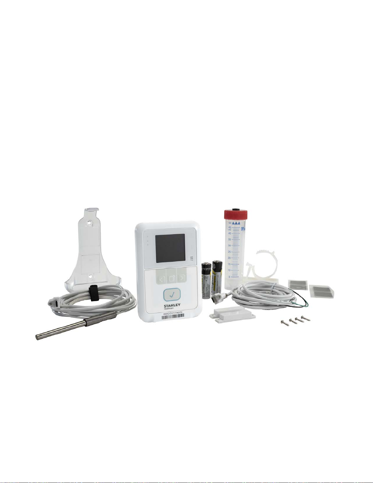
What’s in the Box?
The T15e Tag is supplied with the following components:
T15e Tag
2 AA Batteries
3 Meter USB-C Temperature Probe
3 Meter USB-C Contact Sensor Cable and Contacts
Tag Mounting Bracket
Plastic Glycol Vial
2 Alcohol Prep Pads
Various Mounting Accessories
7
Page 8

T15e Tag Deployment & User Guide
Components
Version
MobileView
Engine
Deployment
Manager (DM)
KB
Document Name
11755
11756
11754
See KB
9758
Pre-Requisites
Minimum Requirements
5.4 and above
5.4 and above
3.2
Reference Documentation
The following articles can be accessed by logging into the STANLEY
Healthcare Support Community site at the following URL:
www.stanleyhealthcare.com/support.
T15e Tag Data Sheet
T15e Tag Release Notes
T15e Tag Deployment & User Guide (This doc)
Refer to any MobileView Administrator Guide from 5.4 and above
Deployment Manager Setup & User Guide
8
Page 9

T15e Tag Deployment & User Guide
Large Display and Push Button Functionality
Audio and Visual Indications
Wi-Fi & Cyber Security
Bluetooth Low Energy (BLE) Communication
Beaconing and Bdirectional (BD) Communication
Battery and External Power Options
T15e Features
T15e Tag Key Features
The tag’s display shows the current temperature, the minimum and maximum
temperatures measured since the last audit, battery and power status, and
alarm indications. The buttons are used to navigate and select the tag’s menu
options, activate the tag, and perform manual audits with a single-press.
T15e Tags include a buzzer with 4 different distinct sounds and 3 LEDs for
status indications, such as tag activation, alerts and low battery.
The tag supports 802.1x Enterprise security networks with a PEAP-MSCHAPv2
protocol. Additionally they support a HTTPs connection with MobileView
Servers using the TLS1.2 protocol. This allows a MobileView Server
authentication using pre-installed X.509 certificates.
T15e Tags use BLE technology to communicate with the Deployment Manager
(DM) app for device configuration and setup.
The tags utilize lightweight beaconing communication (for standard messages)
and Bidirectional Wi-Fi communication with full network association and
authentication. This unique combination provides a flexible and scalable
solution for advanced applications. The tags can operate with one network
SSID in a secure or non-secure mode and is able to store up to two application
server connections. The T15e Tags also support both static IP configuration
and DHCP.
The tags are powered by 2 AA batteries, which is the recommended power
source, and an optional power adaptor which can be used to save battery life.
Battery levels are constantly monitored by the device and MobileView. The tag
will use external power whenever available (batteries are recommended as a
backup if external power is used).
9
Page 10

T15e Tag Deployment & User Guide
Multi-Purpose USB-C Connector Interface
Detachable Temperature Probe and Contact Sensor
Programmable Logging Interval
Manual Audit with a Single Button Press
Stores up to 64,000 Records
Easy Battery Replacement
Off-Line Temperature Monitoring
Flexible Mounting Options
The T15e Tag has 3 multi-purpose USB-C connector ports. Power, temperature
probe and contact sensor inputs, can be attached to any of the 3 ports, and
are automatically recognized by the tag.
T15e Tags are supplied with a 3 meter USB-C temperature probe cable for
temperature monitoring, and a USB-C Contact Sensor cable for refrigerator
and freezer door monitoring.
Logging intervals can be programmed to 5, 15, 30 or 60 minute intervals using
pre-configured static configurations.
The CDC requires healthcare facilities to inspect physically (also called "audit")
each VFC enabled device at least twice a day (once during the morning and
once during the afternoon shift). A physical inspection is logged when the main
button on the front of the tag is pressed.
The T15e Tag’s on-board memory can store up to 64,000 sampled
temperature records. Additionally, temperature data is also sent to MobileView
(if the tag is configured to sync with MobileView).
The tag uses 2x 1.5V Alkaline AA batteries. Battery levels are constantly
monitored and easily replaced by opening the battery cover on the back of the
tag. The tag’s memory is retained during battery replacement.
The T15e Tag is able to store data during times of network connectivity
failures. Recorded data is then automatically synchronized with MobileView
within 24 hours after normal network connectivity has resumed, or immediately
by performing a manual sync from the tag. Off-line data is viewed via
MobileView Reports.
The tag’s external sensors, and convenient form factor, allows for secure
mounting on variety of assets using its supplied cradle. Other industry-specific
mounting accessories can be supplied by STANLEY Healthcare.
10
Page 11
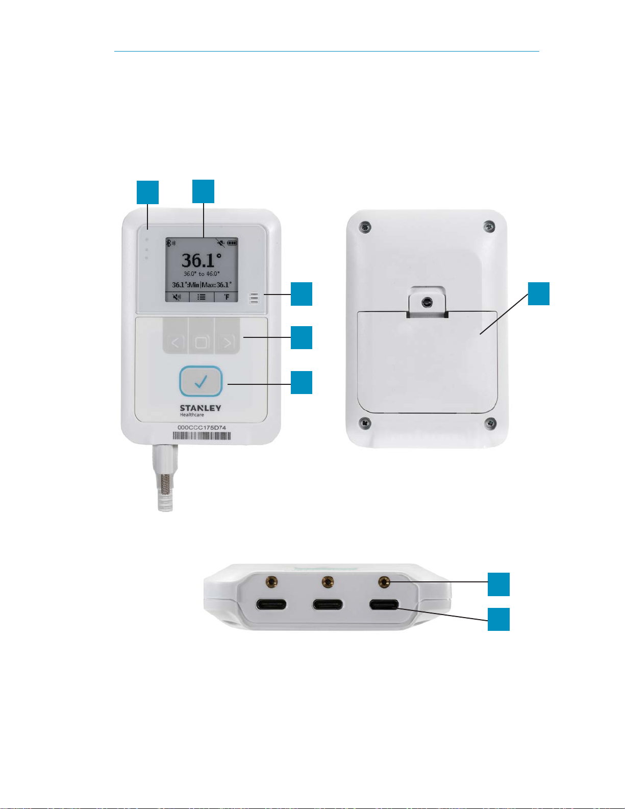
Tag Descriptions
Front View:
Back View:
Bottom View:
1 2 3 4 5 6 7
8
The following describes the parts of the T15e Tag:
T15e Tag Deployment & User Guide
11
Page 12
T15e Tag Deployment & User Guide
No.
Description
1
2
3
4
5
6
7
8
No.
Description
1
2
3
1 2 3
3 indication LEDs – See LED and Buzzer Indications
LCD Screen
Buzzer – See LED and Buzzer Indications
Navigation Arrow Buttons and Select Button
See Using the T15e Tag
Mute Alarm/Audit button
Battery Cover
USB-C Screw Tightening Hole (for securing the cable plug to the tag)
Multi-Purpose USB-C Connectors (Power, Temperature Probe and
Contact Sensor plugs can be plugged into any of the USB-C
connectors).
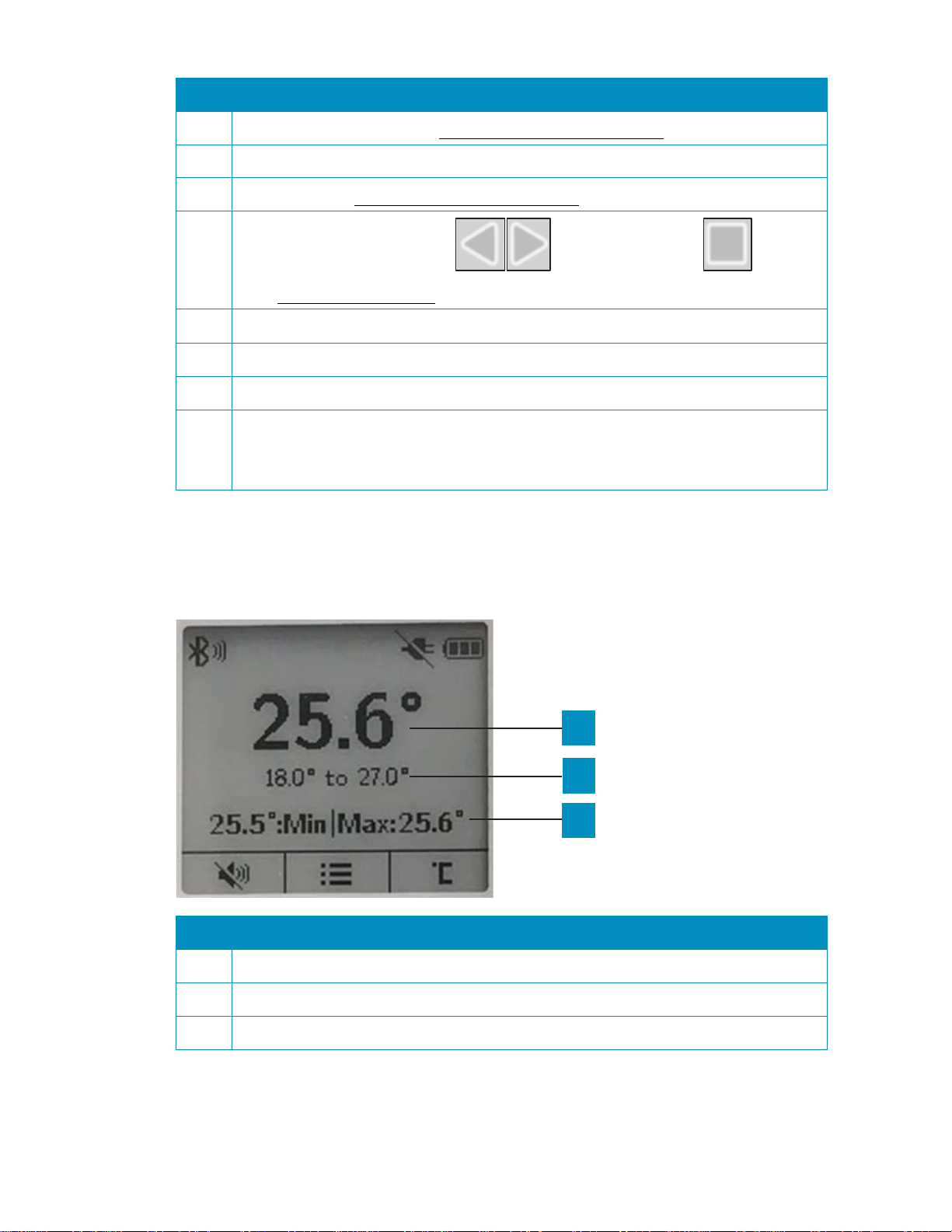
Screen Values
The following explains the tag’s screen values:
Current temperature
The tag’s configured temperature range.
Recorded temperature values since the last audit.
12
Page 13
T15e Tag Deployment & User Guide
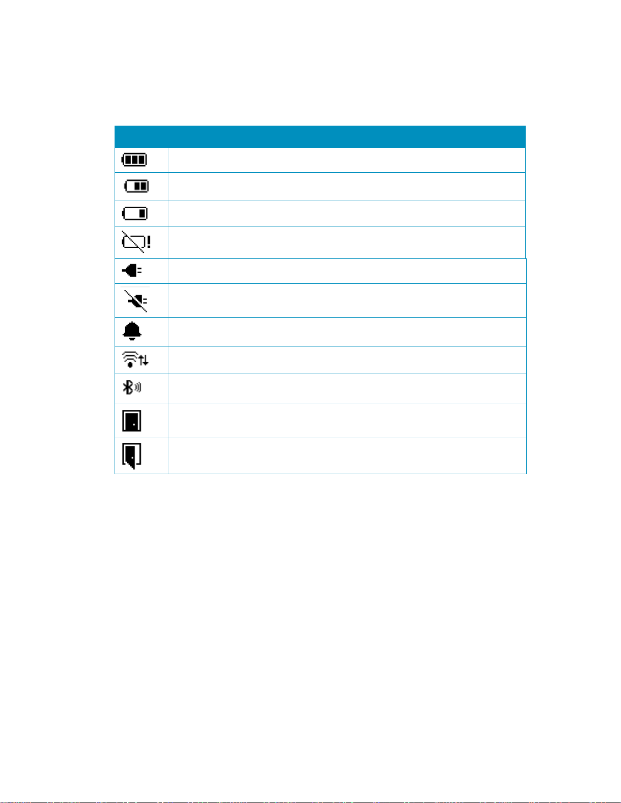
Icon
Description
Status Icons
The tag’s status icons are displayed across the top of the LCD screen. The
following table explains the Status Icons:
Full Battery
Battery Level Medium
Battery Low
Depleted Battery. Change battery immediately
Power cable plugged in and supplying power to the tag
Power cable disconnected
Temperature out-of-range Alert / Local Alarm
Bidirectional (BD) Session in progress
BLE Session in progress
Contact Sensor Closed
Contact Sensor Open
13
Page 14

T15e Tag Deployment & User Guide
Select
left arrow
right arrow
Select
Option
Description
Main Screen
BLE Activation
Tag Sync
Show Thresholds
Tag Functions
The navigation buttons are used to navigate and select a menu option, change
the temperature scale and enable or disable the button sound. The tag’s main
button is used for tag activation, muting alarms and performing temperature
audits.
Accessing and Using the Tag’s Menu Options
The tag’s menu options are indicated by the menu icon .
1. Press the
2. Use the
down, to navigate through the menu.
3. To select an option, navigate to the required option and press the
button .
button to access the menu.
button for up, and the
button for
Tag Menu Options
Displays the tag’s main screen.
Select this option to activate a BLE session with the
Deployment Manager (DM) app. The BLE will be
active for 30 min.
Select this option to activate a BD session with
MobileView.
Shows or Hides temperature out-of-range threshold
values on the main screen.
14
Page 15

T15e Tag Deployment & User Guide
Note:
Product Key
Activating and Configuring the
Tag
T15e Tags arrive deactivated and must be activated and configured before
use.
Tag Activation
The tag is automatically activated once power is supplied to the tag (battery or
external power). The tag will beep when it turns on and is activated, and a blue
LED will flash. The tag will also automatically activate its BLE and will be ready
for configuration via the DM app. The tag’s BLE will be activated for 30 min.
Additionally, if the tag was deactivated using the DM app, the tag can be
activated again by pressing the main button on the front of the tag for 3
seconds.
Tag Configuration
It is recommended to use the Deployment Manager (DM) Setup & User Guide
together with the procedures below.
T15e Tag parameters must be initially configured using the DM app’s BLE Tag
Functions feature. The feature needs to be enabled using a product key. See
below:
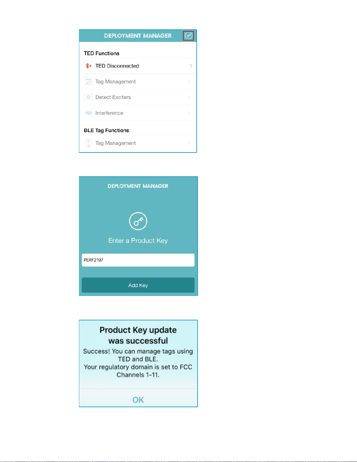
Enabling BLE Tag Functions
BLE Tag Functions is enabled (disabled by default) using the product key
PERF2197. The key only needs to be entered in once. If you delete the DM
app, the key will need to be re-entered.
11. Opening channels 12 and 13 is country-dependent and requires a specific
key from STANLEY Support.
This key opens Wi-Fi channels 1-
1. Open the DM app.
2. Tap the
icon.
15
Page 16
T15e Tag Deployment & User Guide
PERF2197
Add Key
OK
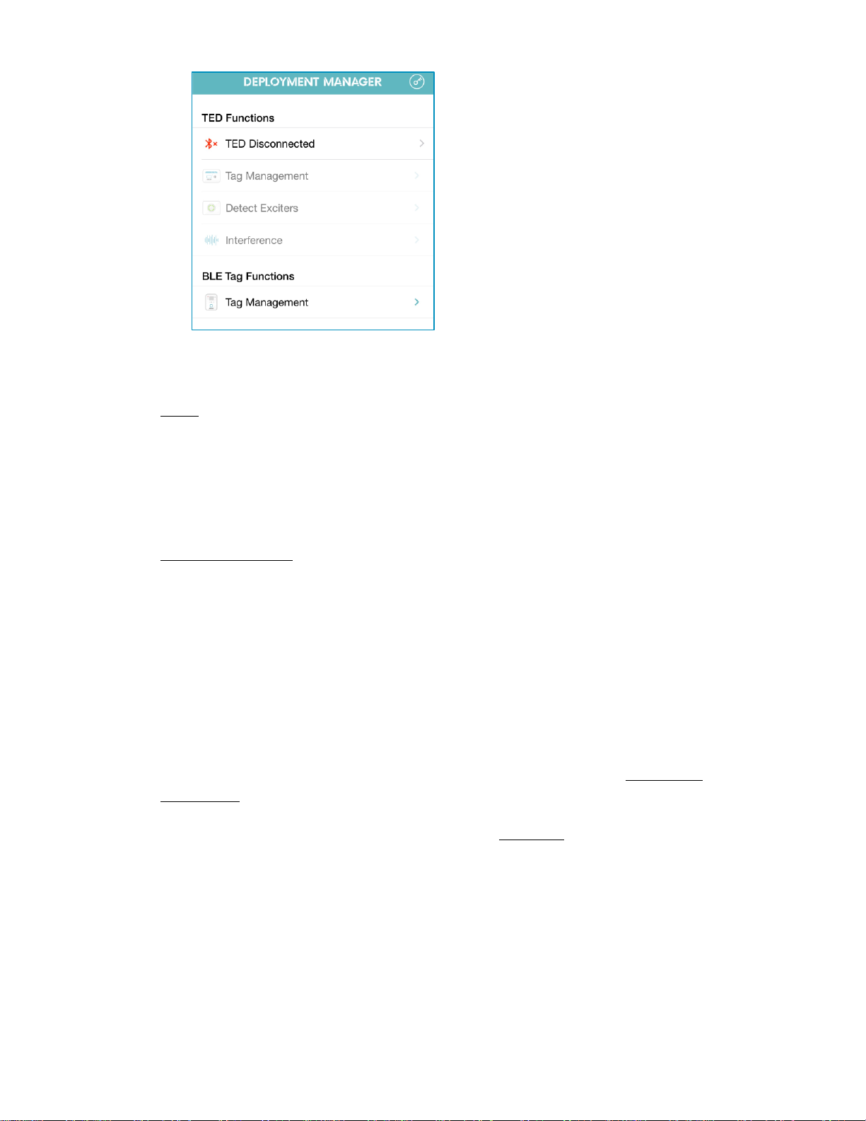
BLE Tag Functions
Tag Management
3. Enter the Product Key
4. Tap
.
.
5. Tap
6.
.
>
is now enabled.
16
Page 17
T15e Tag Deployment & User Guide
Note
Root CA
Enabling Secured Tag Communication with MobileView
: This section is for sites that are using MobileView in a secured mode
and require secure BD (Bidirectional) tag sessions. For more information on
using MobileView in a secured mode, refer the latest MobileView Deployment
Guide.
Skip this section if the site is not using MobileView in a secured Mode or if you
will be deploying the tag in a UD (Unidirectional) environment. See
Configuring Tags.
T15e Tags support a HTTPs connection with MobileView Servers using the
TLS1.2 protocol. This allows a MobileView Server authentication using preinstalled X.509 certificates.
The STANLEY T15e Tag Certificate
To allow a MobileView Server authentication using the Server’s SSL certificate,
the T15e Tag must be pre-loaded with a Root CA certificate that authenticates
the MobileView Server’s SSL certificate. This can be done either directly, or
through an Intermediate Certificate using a Chain of Trust (see Certificate
Definitions).
The T15e Tag must be pre-loaded with only a
certificate. Any other
certificate that is pre-loaded to the tag will fail the Server’s SSL certificate
verification.
Certificate Format
T15e Tags can be pre-loaded with a Root CA certificate in X.509v3 PEM format
(also known as Base64 encoded certificates that starts with “-----BEGIN
CERTIFICATE-----” and ends with “-----END CERTIFICATE-----”).
17
Page 18

T15e Tag Deployment & User Guide
MobileView Server Certificates
The following certificates must be pre-installed on the MobileView Server to
allow the certificate validation to be performed by T15e Tags:
• SSL Certificate issued for this specific server
• All Intermediate Certificates
• Root CA Certificate
If one of the above certificates from the Chain of Trust is not installed on the
MobileView Server, the T15e Tag will fail the Server’s SSL certificate
verification.
MobileView Server Host Name
The MobileView Server’s host name must always include its domain (i.e. mvsrv-1.corp.aeroscout.com). The domain must correspond to the CN set in
‘subject’ field of the MobileView Server’s SSL certificate.
Certificate Definitions
T15e Tag certificate-based authentication of the MobileView Server is based
on the following definitions:
Chain of Trust
A certificate chain is an ordered list of certificates, containing an SSL
Certificate, Intermediate Certificates and a Root CA Certificate, that enable the
receiver to verify that the sender and all CA's are trustworthy.
The chain must begin with the MobileView Server’s SSL certificate, and each
certificate in the chain must be signed by the entity identified by the next
certificate in the chain.
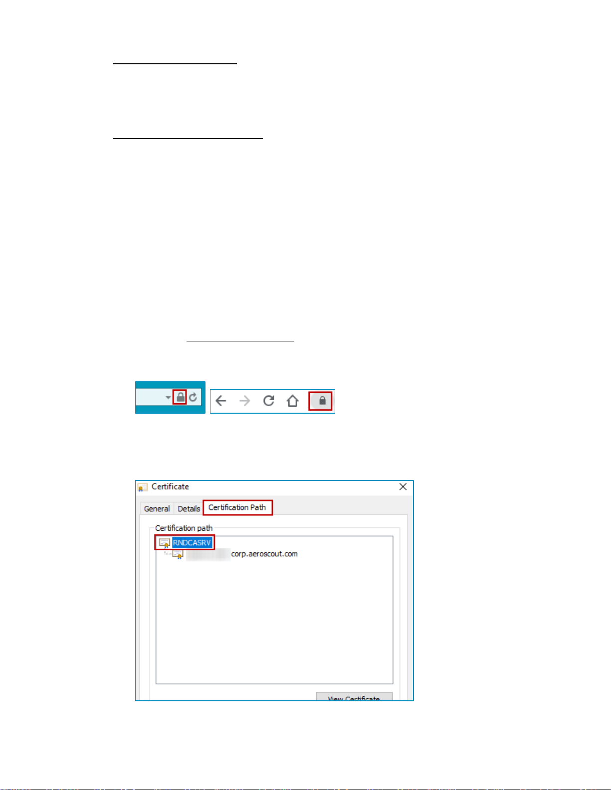
The below figure illustrates a certification path from the Server’s SSL
Certificate to the Root CA Certificate, where the Chain of Trust begins:
18
Page 19
T15e Tag Deployment & User Guide
Lock
View certificates
Certificate
Certification Path
The Root CA certificate
The chain ends with a Root CA Certificate. The Root CA Certificate is always
signed by the CA itself. Using this certificate T15e Tags are able to verify the
signatures of all certificates in the chain.
The Intermediate Certificate
Any certificate that sits between the SSL Certificate and the Root CA
Certificate is called a chain or Intermediate Certificate. The Intermediate
Certificate is the signer/issuer of the SSL Certificate. The Root CA Certificate is
the signer/issuer of the Intermediate Certificate. If the Intermediate Certificate
is not installed on the MobileView Server (where the SSL certificate is installed)
it will prevent T15e Tags from completing the server’s SSL certificate
verification.
Exporting a Secured Certificate from MobileView
A secured server Certificate is exported from MobileView by doing the
following:
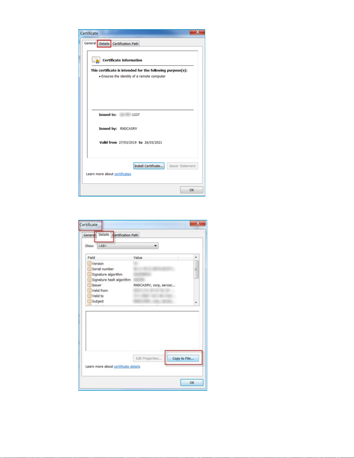
Open the secured MobileView in a browser (use the full DNS name). 1.
Click on the
Click on
Click on the
icon in the browser- IE or Chome. 2.
(IE) or
tab. 4.
(Chrome). 3.
Double click on certification name. 5.
19
Page 20
T15e Tag Deployment & User Guide
Details
Copy to file…
Next
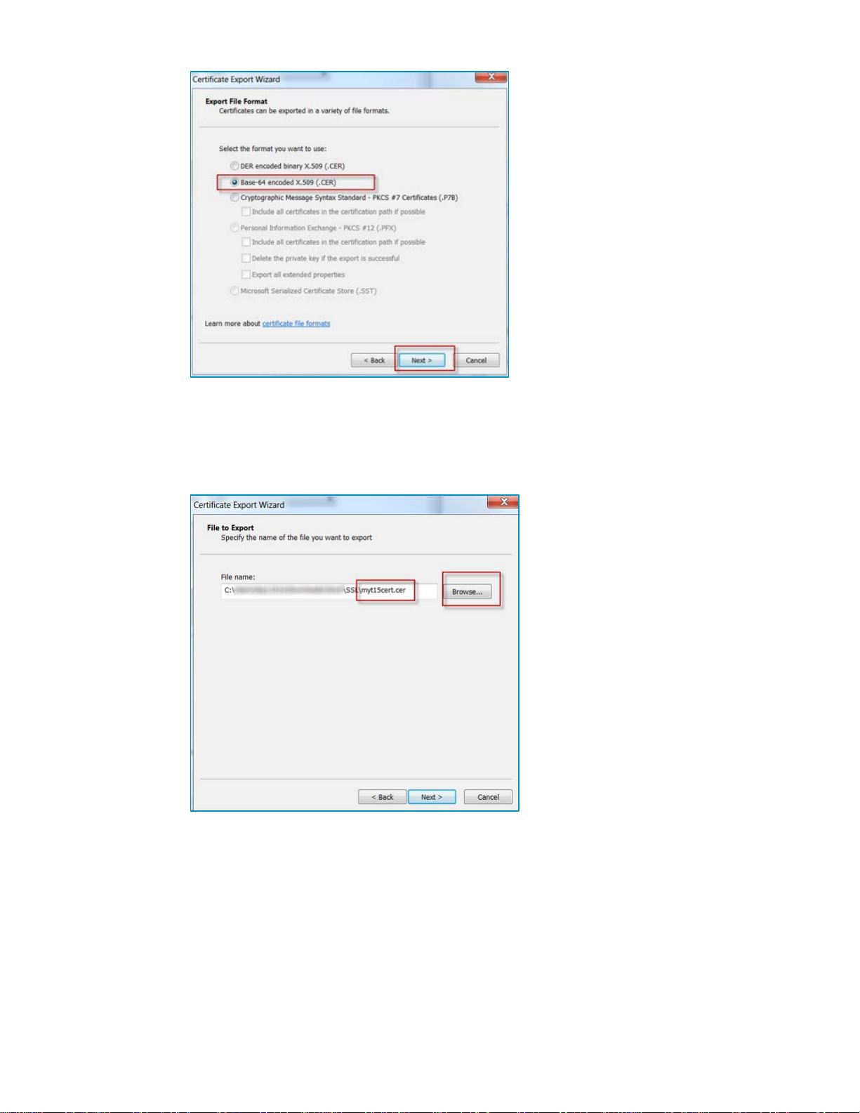
Base-64 encoded X.509 (.CER)
Select the
tab and then click on
6.
Click
Select
on the Welcome Page 7.
. 8.
20
Page 21
T15e Tag Deployment & User Guide
Next
Next
Finish
.cer
.certificate
Click
Enter the file’s name and select a location to save the file (the extension 10.
will be *.cer).
to Export the File. 9.
Click
and then
The Certificate is saved.
Navigate to the location of the saved Certificate. Locate the Certificate and 12.
rename its extension from
Send the secured Certificate to your mobile device, either by email or any 13.
other file sharing app.
. 11.
to
. Example; mycert.certificate.
21
Page 22
T15e Tag Deployment & User Guide
Note: Previously installed Certificates will be deleted.
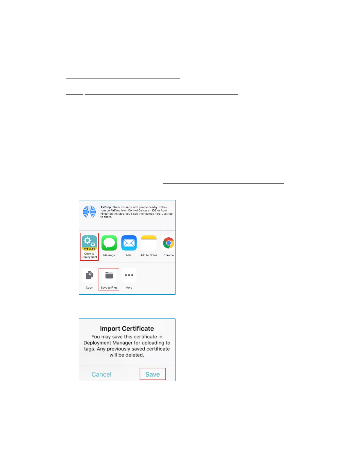
Loading from Email:
Copy to Deployment
Manager’
Copy to Deployment Manager
Save to Files
iCloud Drive
Save
OK
Loading a Secured Certificate to the Tags
Ensure you have the secured MobileView Certificate available on your mobile
device (either as an email attachment or in a file sharing application). Refer to
Enabling Secured Tag Communication with MobileView and Exporting a
Secured Certificate from MobileView.
From your mobile device, perform either of the following:
1. Tap the required Certificate in your email.
2. The default file operation list will open. Select ‘
tap
. If you don’t have ‘
and save the file to either your
file sharing application (see Loading from a File Sharing Application
below).
’ in your list,
or any other
3. Deployment Manager opens. Tap
.
4. Tap
.
5. Configure the tag accordingly. See Configuring Tags.
22
Page 23
T15e Tag Deployment & User Guide
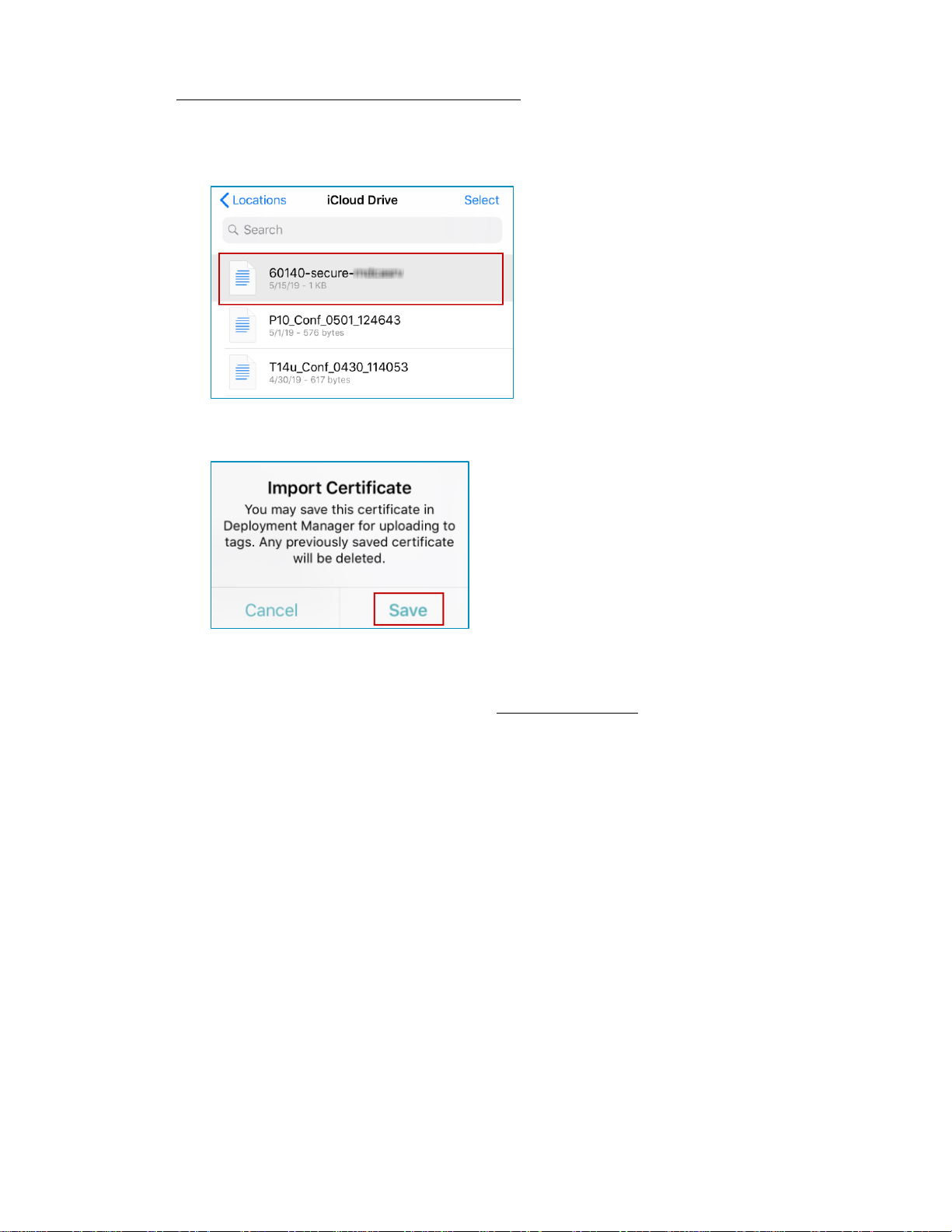
Loading from a File Sharing Application:
Save
OK
1. Tap the required Certificate in your file sharing application, for example
iCloud Drive.
2. Deployment Manager opens. Tap
.
3. Tap
.
4. Configure the tag accordingly. See Configuring Tags.
23
Page 24

T15e Tag Deployment & User Guide
Note:
Select
BLE Activation
BLE Tag Functions
Tag Management
Detect
Configuring Tags
Tag configurations can be saved, loaded or exported. See Saving, Loading or
Exporting Tag Configurations.
Up to 50 tags can be configured at once.
1. Ensure the tag’s BLE is activated, which is indicated by the BLE icon.
BLE is activated when the tag is powered on for the first time.
If the tag’s BLE is not activated, press the
button on the tag to
access the menu options. Use the arrow buttons to navigate, and then
select
.
Ensure the BLE icon is displayed on the main screen.
2. Open the DM app.
3. Under
, tap
.
4. Tap
or swipe down on the screen to detect the tags.
24
Page 25

T15e Tag Deployment & User Guide
Configuration
Note
VFC sites must use the BD Deployment only.
5. Tap to select the required T15e Tag(s) and then tap
50 tags can be configured at once.
. Up to
6. Configure the tag accordingly (See About UD and BD Deployments).
25
:
Page 26

T15e Tag Deployment & User Guide
UD Deployment
BD Deployment
Does not support CDC
requirements for VFC deployments
Supports CDC requirements for
VFC deployments
Does not support remote firmware
Local Alarm is set only by using the
Wireless Association Off
Data Frame Format
About UD and BD Deployments
The following table shows the differences between a UD (Unidirectional) and
BD (Bidirectional) deployment:
.
Tags only transmit real-time
temperature data to MobileView.
Tags transmit and receive values
and configuration data from
MobileView via a Bidirectional
session automatically every 24
hours (providing there are no
network issues).
Does not support Offline data
uploads.
Supports Offline upload of
temperature values and audit
checks.
Supports firmware upgrades via a
upgrade.
BD session from MobileView.
Local Alarm is configured in
DM app.
MobileView.
UD (Unidirectional) Deployment Configuration
.
Configure the following in the DM app:
1. Turn
2. Set the site’s
(enabled by default).
(default is IBSS).
26
Page 27

T15e Tag Deployment & User Guide
Configuration ID
ID
Description
ID 175
ID 176
ID 177
ID 178
Channels
Sensor Settings
Wireless Association
Sensor Settings
Temperature Units:
3. Select a
and then tap Apply .
These are pre-defined configurations. One ID must be selected. You can
view more details about each ID by tapping on the information icon .
5min Beacon (sets the tag’s transmission and logging
interval to 5min).
15min Beacon (sets the tag’s transmission and logging
interval to 15min).
30min Beacon (sets the tag’s transmission and logging
interval to 30min).
60min Beacon (sets the tag’s transmission and logging
interval to 60min).
4. Set the Wi-Fi
accordingly (default is 1, 6, 11) and then tap Apply
.
5. Tap
is turned Off).
6. Configure the
(this option is only available if
:
a.
Select the temperature unit (Celsius/Fahrenheit).
27
Page 28

b.
Temperature & Alarm Settings
Local Alarm:
Note:
Min & Max Temperature Thresholds:
Alarm Delay Period:
Note:
Apply
Done
T15e Tag Deployment & User Guide
:
The Local Alarm includes 3 components; Buzzer,
Alert LED and the on-screen Bell icon. These are all triggered if
the configured temperature values are out of range. By default
the (in UD mode) Local Alarm is ‘On’, and can be turned ‘Off’ by
toggling the button.
The buzzer will continue to sound unless muted on the tag
itself.
Set the minimum and
maximum temperature threshold values. The tag’s Local Alarm
will be triggered when a value is out of its configured range.
Select the time period that a tag’s value
must be out of a configured range before an alarm is triggered.
For example; if the alarm delay period is set to 5 minutes and the
tag’s value is out of its configured range, the alarm will only be
triggered if its value does not normalize within the set time of 5
minutes.
The tag will immediately move out of alarm mode when
the temperature is back within the configured limits.
7. Apply the tag configuration by tapping the check icon .
8. Tap
to apply the settings to the tag(s).
9. Ensure all tag configurations are successful and then tap
.
28
Page 29

T15e Tag Deployment & User Guide
Wireless Association
Note:
Wireless
Association
Sensor Settings
Data Frame Format
Configuration ID
ID
Description
ID 175
ID 176
ID 177
ID 178
Channels
BD (Bidirectional) Deployment Configuration
Configure the following in the DM app:
1. Ensure
is enabled, the
is enabled (default).
now receive sensor settings from MobileView.
2. Set the site’s
3. Select a
(default is CCX).
and the tap Apply .
When
tab is disabled. The tag will
These are pre-defined configurations. One ID must be selected. You can
view more details about each ID by tapping on the information icon
The following table explains each Configuration ID:
5min Beacon, 2 days BD (sets the tag’s transmission
and logging interval to 5min and sets a BD session for
every 2 days).
15min Beacon, 2 days BD (sets the tag’s transmission
and logging interval to 15min and sets a BD session for
every 2 days).
30min Beacon, 2 days BD (sets the tag’s transmission
and logging interval to 30min and sets a BD session for
every 2 days).
60min Beacon, 2 days BD (sets the tag’s transmission
and logging interval to 60min and sets a BD session for
every 2 days).
4. Set the Wi-Fi
.
accordingly (default is 1, 6, 11) and then tap Apply
29
Page 30

T15e Tag Deployment & User Guide
Wireless
Wireless Association
Wireless Settings
IP SETTINGS
Address Type
DHCP
-OR-
Static IP
Note:
Static IP
DHCP
Auto IP Renewal
5. Tap
(this option is only available if
enabled).
6. Enter the required
is
:
a. Tap on
automatically assigns the tag an IP address every time the tag is
associated with the network),
manually).
selected.
b. If
renewal time in hours (this automatically renews the IP address
according to the selected time period). If ‘None’ is selected, the
tag will be issued an IP address from the DHCP server during
each BD session.
:
and select either
(The DHCP server
(the IP address and connection settings are specified
The
is selected, tap on
setting is not available if more than one tag is
and select the
30
Page 31

T15e Tag Deployment & User Guide
Static IP
IP Address, Subnet
Gateway
APPLICATION SERVERS (a minimum of 1 must be added, with a
maximum of 2):
Add Application Server.
c. If
is selected, enter the
.
and
a. Tap
The following screen is displayed if you have not loaded a secure
Certificate from MobileView. To load a secured Certificate, refer
to the Enabling Secured Tag Communication with MobileView
section.
Any loaded secured Certificate from MobileView is displayed:
31
Page 32

Enter the MobileView Server details:
Port
Protocol: HTTPS
HTTP
Apply
Note:
Missing Information
WI-FI (1 must be added):
Add Wi-Fi Network
SSID
Authentication
Open / WPA2-PSK / 802.1X
(PEAP-MSCHAPv2).
WPA2-PSK
Authentication Key
IP or Host name of the Server.
T15e Tag Deployment & User Guide
The Server’s
certificate to authenticate MobileView’s server certificate to
ensure a secured connection. Use
a secured connection.
b. Tap the
An HTTPS configuration can only be applied if a certificate
is loaded. A
certificate is loaded.
(default is 443).
(default setting) uses a loaded root
icon to apply the settings.
message appears if no HTTPS
if you are not using
a. Tap
b. Enter the Network’s
c. Select the
d. For
enter in the
.
.
method;
.
32
Page 33

T15e Tag Deployment & User Guide
802.1x (PEAP-MSCHAPv2)
Domain
Name \ Username
Password
Apply
Done
e. For
(separated with a backslash\) and
f. Tap the Apply icon .
, enter in the appropriate
.
7. Apply the tag configuration by tapping the check icon .
8. Tap
to apply the settings to the tag(s).
9. Ensure all tag configurations are successful and then tap
.
33
Page 34

T15e Tag Deployment & User Guide
Tag Configuration, Tag Settings
Wireless Settings
Save Configuration
name
Save File.
OK
Tag Configuration, Tag Settings
Wireless Settings
Export Configuration
name
Export File.
.
Saving, Exporting, Importing and Loading Tag Configurations
Tag configurations, tag settings and wireless settings can be saved, exported
or loaded. Saved files are stored to the DM app. Additionally, .tfg3 files that
have been sent to you can be imported. Saved or exported configurations can
be loaded to single or multiple tags. Refer to the Deployment Manager Setup
& User Guide for more information.
Saving Configurations
Configurations are saved to your DM app.
1. From either the
screens, tap .
2. Select
3. Enter a
4. Tap
for the file.
The configuration is saved.
5. Tap
.
Exporting a Configuration
1. From either the
screens, tap .
2. Select
3. Enter a
for the file.
or
.
or
.
4. Tap
5. Select where to export the file
The file will be exported in a .tfg3 format. The file can then be sent from
your mobile device to other recipients. The file can also be used for
troubleshooting by STANLEY Healthcare Support.
Importing and Loading a Tag’s Configuration
Tag configurations that have been saved to your app can be loaded to single
or multiple tags. Saved configurations could either be files that you saved or
files that have been sent to you by a STANLEY Support representative.
34
Page 35

T15e Tag Deployment & User Guide
Importing .tfg3 Files:
iOS Mail -
Google Drive App
Dropbox App
Gmail App
iCloud Drive
Save to File
Loading a Saved Configuration to a Single Tag
Tag Configuration, Tag Settings
Wireless Settings
Load Configuration
Load File.
OK
When receiving configuration files from STANLEY, the file must be imported
and saved to the DM app first.
Tapping the file will open the default file operation list. Select
‘Copy to Deployment Manager’. The application will open allowing you to
save the file.
- Tap the 3 dots menu (in the file row) and select
‘Export’. The default file operation list will open. Select ‘Copy to
Deployment Manager’. The application will open allowing you to save the
file.
- Tap the 3 dots menu (in the file row) and select “Export”.
The default file operation list will open. Select ‘Copy to Deployment
Manager’. The application will open allowing you to save the file.
- Tap the file attachment in the email and then tap the share icon
in the top right corner. The default file operation list will open. Select ‘Copy
to Deployment Manager’. The application will open allowing you to save
the file.
Additionally when using the above the methods, the file can also be saved to
your
by tapping on ‘
’.
1. From either the
screens, tap .
2. Select
.
3. Select the required file.
4. Tap
The configuration will be loaded.
or
5. Tap
.
35
Page 36

Loading a Saved Configuration to a Multiple Tags
Detected BLE Tags
Configuration
Options
Load Configuration
Load File.
OK
T15e Tag Deployment & User Guide
1. From the
2. Tap on
3. Tap the
4. Select
.
icon .
list, select the required tags.
.
5. Select the required file.
6. Tap
The configuration will be loaded.
7. Tap
.
Viewing a Tag’s Current Configuration
You can view a tag’s current configuration by doing the following:
1. Enable the tag’s BLE.
2. Detect the tag.
3. Tap the information icon of the tag to view.
4. The tags details will be displayed in read-only mode.
36
Page 37

T15e Tag Deployment & User Guide
Sensor Settings
Wireless
5. You can view the tag’s sensor settings (UD deployments) by tapping the
6. If the tag is configured for BD deployments, then tap the
tab.
tab to
view the settings.
7. To Save, Load or Export configurations, tap .
37
Page 38

T15e Tag Deployment & User Guide
Note:
Detect
TRANSMISSION SETTINGS
Edit Configuration
Tag Details
Editing Transmission and Sensor Settings (UD Deployments)
Only one tag can be edited at a time. If you need to edit multiple tags,
edit one tag, save the configuration and then load the new configuration to the
other tags. See Saving, Exporting, Importing and Loading Tag Configurations.
Tag Transmission and/or Sensor Settings of UD deployed tags are edited by
doing the following:
1. Enable the tag’s BLE.
2. Open the DM app and
the tag.
3. Tap the information icon of the tag to edit.
4. The tags details will be displayed in read-only mode.
5. To Edit the tag’s
icon on the
screen.
, tap the
38
Page 39

T15e Tag Deployment & User Guide
Sensor Settings
Sensor Settings
Edit Configuration
Temperature Units:
6. Edit the tag’s configuration accordingly. See UD (Unidirectional)
Deployment Configuration. If you are changing the tag’s deployment from
UD to BD, then see BD (Bidirectional) Deployment Configuration.
7. To Edit the tag’s
8. If needed, tap the
, tap the
icon.
tab.
9. Edit the tag’s sensor settings accordingly.
a.
Select the temperature unit (Celsius/Fahrenheit).
39
Page 40

b.
Temperature & Alarm Settings
Local Alarm:
Note:
Min & Max Temperature Thresholds:
Alarm Delay Period:
Note:
Options
Apply
Done
T15e Tag Deployment & User Guide
:
The Local Alarm includes 3 components; Buzzer,
Alert LED and the on-screen Bell icon. These are all triggered if
the configured temperature values are out of range. By default
the (in UD mode) Local Alarm is ‘On’, and can be turned ‘Off’ by
toggling the button.
The buzzer will continue to sound unless muted on the tag
itself.
Set the minimum and
maximum temperature threshold values. The tag’s Local Alarm
will be triggered when a value is out of its configured range.
Select the time period that a tag’s value
must be out of a configured range before an alarm is triggered.
For example; if the alarm delay period is set to 5 minutes and the
tag’s value is out of its configured range, the alarm will only be
triggered if its value does not normalize within the set time of 5
minutes.
The tag will immediately move out of alarm mode when
the temperature is back within the configured limits.
10. To Save, Load or Export a configuration, tap the
11. Tap the
icon to apply the new configuration.
12. Ensure all tag configurations are successful and then tap
icon.
.
40
Page 41

T15e Tag Deployment & User Guide
Note:
Detect
TRANSMISSION SETTINGS
Edit Configuration
Tag Details
Editing Transmission and Wireless Settings (BD Deployments)
Only one tag can be edited at a time. If you need to edit multiple tags,
edit one tag, save the configuration and then load the new configuration to the
other tags. See Saving, Exporting, Importing and Loading Tag Configurations.
Tag Transmission and/or Wireless Settings of BD deployed tags are edited by
doing the following:
1. Enable the tag’s BLE.
2. Open the DM app and
the tag.
3. Tap the information icon of the tag to edit.
4. The tags details will be displayed in read-only mode.
5. To Edit the tag’s
icon on the
screen.
, tap the
41
Page 42

T15e Tag Deployment & User Guide
Tag Configuration
Wireless Settings
Wireless
Edit Configuration
Options
Apply
Done
6. Edit the
accordingly. See BD (Bidirectional)
Deployment Configuration. If you are changing the tag’s deployment from
BD to UD, see UD (Unidirectional) Deployment Configuration.
7. To Edit the tag’s
, tap the
tab.
8. If needed, tap the
icon.
9. Edit the tag’s wireless settings accordingly. See the BD (Bidirectional)
Deployment Configuration section.
10. To Save, Load or Export a configuration, tap the
11. Tap the
icon to apply the new configuration.
12. Ensure all tag configurations are successful and then tap
icon.
.
42
Page 43

T15e Tag Deployment & User Guide
Category
this can be done on an Asset or
Category level
Temperature Sensor & VFC
Deployments
This section explains how to configure the T15e Tag for use as a Temperature
Sensor and assumes familiarity with MobileView.
Configuring MobileView
Please refer to the latest MobileView Administrators Guide on the STANLEY
Healthcare Knowledge base and perform the following. Ensure the tag is
available in MobileView under the ‘Tags’ tab.
If the tag is setup for UD, MobileView will only receive data from the tag and
trigger alerts according to configured events.
If the tag is setup for BD, MobileView will transmit data, such as temperature
threshold values to the tag, and receive data from the tag. Alerts will be
triggered according to configured events.
Creating / Editing a Category
1. Create or edit a
2. Define the temperature thresholds (
):
and give it a meaningful name.
43
Page 44

T15e Tag Deployment & User Guide
Setting Thresholds on a Category Level:
Set custom temperature thresholds for this category
Minimum
Maximum temperature
Maximum Temperature
Maximum Temperature
Set temperature status to
Trigger alert after:
Setting Thresholds on an Asset Level:
Set
custom temperature thresholds for this asset
Setting these values automatically enables the T15e Tag’s Local Alarm.
The entered values will be sent to the tag via a BD session which may
require a few hours to update. You can perform an immediate sync action
from the tag itself. See Performing a Manual Sync with MobileView.
Select
, and enter
the thresholds for all assets that will be placed in this category. Assets in
this category can either inherit these thresholds, or be configured
individually – see Setting Thresholds on an Asset Level below.
Set the
and/or
thresholds. Both or
one temperature threshold can be entered. If a single threshold is
entered, for example just the
monitor and alert when the
, the tag will only
value is reached.
…. This option will change the temperature
status to ‘Warning’ if the temperature is within a specified value of the
set thresholds. For example: If the min threshold is 10 and the
‘Warning’ status is set to 2, the temperature status will change to
‘Warning’ if the min temperature reaches 13 (2 below the max threshold
of 15).
Define the time period that a tag’s value must be
out of a configured range before an Alert is sent. For example; if the
time threshold is set to 15 min and the tag’s value is out of its
configured range, an alert will be triggered if its value does not
normalize within the set time of 15 min.
If configuring temperature thresholds on individual assets, select
and enter the appropriate
values. See above for descriptions.
44
Page 45

T15e Tag Deployment & User Guide
Event Name
Description
Temperature
Battery Level
Out of Sight
External Power (Optional)
Sensor Tag Error
Best Practice Note:
Configuring Events
Events are configured in MobileView to trigger alerts according to specified
parameters.
The following Events should be used for the T15e Tag:
Triggers alerts when the temperature
values are out of a configured range.
Monitors the tag’s battery level and
triggers alerts accordingly.
Additionally, an alert can be triggered if the
tag has no batteries or they are removed.
Triggers alerts if the tag fails to report for a
specified time.
Triggers an alert if the tag’s external power
supply is disconnected for a period of time.
Triggers alerts when a sensor error occurs
which prevents data from being received.
Such as, a probe disconnection or probe
malfunction etc.
Temperature Event
This event issues an alert based on temperature readings transmitted by
active tags equipped with a temperature sensor. You can set specific
conditions for the alert or inherit the asset / category thresholds and set the
delay time before an alert is triggered.
Asset / Category. Only set local conditions when required.
It is recommended to inherit the configuration from the
45
Page 46

T15e Tag Deployment & User Guide
Set event condition in absolute terms:
Set event conditions relative to the assets’ predefined limits:
Set trigger time
Only Trigger after
Asset default time
Alert when no temperature reports have been received for: NOTE:
Sensor Tag Error Event
Best Practice Note:
Action Type
Message Template
Measurements Message
Selected Alert Fields
Event Conditions
Configure the Event Conditions according to the following:
If you want to set a specific (not
inherited from the asset / category level) temperature range that triggers an
alert, enter it here.
Select this
option to use thresholds defined on the asset / category level.
:
: Define the time period that a tag’s value must be out of
a configured range before an Alert is sent. For example; if the time
threshold is set to 15 min and the tag’s value is out of its configured range,
an alert will be triggered if its value does not normalize within the set time
of 15 min.
: Select this option to use the value defined on the
Asset / Category level.
This
option must not be used as it will be removed in a future version. It is
recommended to create a
instead. See Sensor
Tag Error Event.
It is recommended to inherit the configuration from the
Asset / Category. Only set local conditions when required.
Actions
Set the actions accordingly.
When using the Email
, select the
. This email template contains details about the
contact sensor value.
as
Additionally when using INF, you can choose to display the Sensor Type and
Value in the
.
46
Page 47

T15e Tag Deployment & User Guide
For tags which report battery status only (Recommended setting):
Asset has not reported its location for
Battery Level Event
This Event issues an alert if a tag’s battery power reaches a certain level or if
the tag has no battery.
Event Conditions
Configure the Event Conditions according to the following:
Select a
level under which an alert will be generated. For example if you select
Medium, the alert will be issued when the battery power level falls below
Medium.
Actions
Set the actions accordingly.
Out of Sight Event
This event will trigger an alert if the tag fails to report for specified period.
Event Conditions
Configure the Event Conditions according to the following:
: Specify the time that should elapse
without receiving a report for the asset to be considered out of sight.
Actions
Set the actions accordingly.
47
Page 48

T15e Tag Deployment & User Guide
Power is disconnected for
Sensor has an error for
External Power Event (Optional)
This event will trigger an alert if the tag’s external power is disconnected for a
period of time. This event does not need to be configured if you are running
the tags with batteries only.
Event Conditions
Configure the Event Conditions according to the following:
: Specify the time that should elapse after the tag’s
external power is disconnected, before an alert is triggered.
Actions
Set the actions accordingly.
Sensor Tag Error Event
This event will trigger an alert if an error occurs with the tag’s sensor
preventing data from being transmitted, such as a probe or contact
disconnection or malfunction.
Event Conditions
Configure the Event Conditions according to the following:
: Specify the time that should elapse after a sensor
error occurs, before an alert is triggered.
Actions
Set the actions accordingly.
48
Page 49

T15e Tag Deployment & User Guide
Best Practices
Sensor Monitor Event
Sensor Monitor Event
Sensor Monitor Event
Add
Sensor Monitor Event
Priority
High
Reset Interval
Configuring the Contact
Sensor
This section explains how to configure the T15e Tag’s Contact Sensor and
assumes familiarity with MobileView.
The Contact Sensor can be used to monitor the door of the fridge or freezer
that the temperature is being monitored. An alert will be triggered if the door
has been left open for a configured amount of time.
The Door Open Event (how long the door can remain open) should be
triggered according to the fridge’s contents.
An Event can be created to automatically dismiss the Door Open Event.
This event can be created to avoid users from manually dismissing the
event from the system. It is recommended if it an action audit is not
required.
Configuring the Sensor Monitoring Event
The Contact Sensor Monitoring Event is configured in MobileView to trigger
alerts when a fridge’s or freezer’s door is left open for a configured period of
time.
Configuring a Door Open Event
The following section explains how to create a door open event using the
Create a
Select
such as VFC Fridge Door.
Set
Set the
alerts, for this Asset, if the alert is triggered again before the reset
interval time – wait time)
a new
.
according to the following: 1.
.
to
.
to 86400. (This prevents triggering additional
and name the event accordingly,
49
Page 50

T15e Tag Deployment & User Guide
Subscribers
Event Conditions
Sensor Type
Contact Sensor
'Sensor Level is
Only trigger after
Remind me every
Actions
Action Type
Message Template
Measurements Message
Selected Alert Fields
Scheduling
Finish
Under
Under
Set
door is opened.
open for a configured period. For example, when a door has been left
open for 30 seconds an alert is triggered.
, subscribe to the correct category. 2.
: This setting triggers the alert when a door has been
, select the
as
. 3.
= ‘0' -. This value will trigger an alert when the
Optional:
: Once an alert has been dismissed, this
setting can be used to check if the condition still persists and trigger an
alarm every X minutes. The alert is generated during the next tx
Interval. This setting should be used if a long tx interval has been set
for the tag and where responding to alerts is time sensitive.
Under
, select the required action to be taken when an alert is 4.
triggered, such as sending an Instant Notifier or email alert.
When using the Email
, select the
. This email template contains details about the
contact sensor value.
Additionally when using INF, you can choose to display the Sensor Type
and Value in the
Under
, select the scheduling time when the alert must be 5.
.
active. For example, monitor the door during night hours only.
Click
. 6.
as
50
Page 51

T15e Tag Deployment & User Guide
Sensor Monitor Event
Sensor Monitor Event
Add
Sensor Monitor Event
Priority
Medium.
Reset Interval
Subscribers
Event Conditions
Sensor Type
Contact Sensor
'Sensor Level is
Only trigger after
Remind me every
Configuring an Automatic Dismiss Door Open Event
This event will automatically dismiss the Door Open Event once the door is
closed.
Create a
Select
a new
such as Auto Dismiss Open Door Alert.
Set
Set the
Under
to
to 300.
, subscribe to the correct category. 2.
according to the following: 1.
.
and name the event accordingly,
Under
Set
is closed.
triggered immediately once the door is closed.
Optional:
setting can be used to check if the condition still persists and trigger an
alarm every X minutes. The alert is generated during the next tx
Interval. This setting should be used if a long tx interval has been set
for the tag and where responding to alerts is time sensitive.
: Set this to ‘0’. This means the event will be
, select the
as
. 3.
= ‘1' -. This value triggers an event when the door
: Once an alert has been dismissed, this
51
Page 52

T15e Tag Deployment & User Guide
Actions
Action Type:
Activate When:
Event to activate action on:
Next
Finish
Under
above (configuring a Door Open Event)
Click
and then click
, create a new action according to the following: 4.
Dismiss Event
Alerts Fires
Select the name of the event created
. 5.
52
Page 53

T15e Tag Deployment & User Guide
IMPORTANT!
Do not
NOTE
Do not
Do not
The Power, Temperature probe
and Contact Sensor cables can be plugged into any port
Mounting and Connecting
Connecting the Power Adapter and Sensors
Batteries are recommended as a backup if external power is used.
It is highly recommended to use an approved STANLEY power supply with
the TAG (SKU: ADP-1500-U, ADP-1500-E). If a different power supply is
used, ensure to connect the power cable to the power outlet first and then
to the T15e Tag’s USB-C port.
IEC/EN/UL 60950-1 with a rated voltage of 5Vdc and rated current up to 3A
maximum.
The T15e Tag is not designed to be powered using a PC’s USB outlet. If a
PC’s USB outlet is used, the Contact Sensor icon on the tag will always
show as “closed”, regardless of the actual state of the Contact Sensor.
T15e Tags are compatible with USB 2.0 cables. Using USB 3.0 cables may
result in inconsistent behavior of the tag.
time. This will cause incorrect temperature values.
connect two USB-C power adapters to the tag at the same time.
: The AC/DC adaptor must be safety approved according to
connect two USB-C temperature probes to the tag at the same
This will cause incorrect alert triggering.
The T15e Tag is only able to monitor Normally Open (NO) contacts.
Make sure the plugs are tightened to the tag.
The T15e Tag has 3 USB-C ports and each cable has a USB-C connector with a
tightening screw:
There is no specific port for each connector.
connect two USB-C contact sensors to the tag at the same time.
.
53
Page 54

T15e Tag Deployment & User Guide
Plug a connector into any port and tighten the tightening screw. The tag will
automatically pick up the source that is connected.
Mounting the Tag
The tag comes with a mounting cradle and double-sided tape for easy
mounting. Additionally, Velcro and screws can be used (not supplied).
Mounting with Double-Sided Tape
Place double-sided tape in each square on the mounting cradle and mount the
cradle accordingly. See Mounting the Tag and Temperature Probe.
54
Page 55

T15e Tag Deployment & User Guide
Click!
Placing the Tag in the Cradle
Place the tag at an angle into the mounting cradle and make sure it clicks in
place:
Removing the Tag from the Cradle
Push the mounting cradle’s clip up and remove the tag:
55
Page 56

T15e Tag Deployment & User Guide
1 Meter Flat section
2 Meter Regular cable
Mounting the Tag and Temperature Probe
The 3 meter Temperature Probe cable has been designed with a 1 meter
Teflon flat section. The flat section enables the cable to be easily fed through a
fridge’s or freezer’s door seal, and helps prevent wear and tear to the cable.
1. Mount the tag on the outside of the unit or in another location close to the
unit.
2. Feed the Probe part of the cable (flat section) through the fridge or freezer
door seal.
56
Page 57

T15e Tag Deployment & User Guide
Door Seal
3. Immerse the Probe slowly into the plastic glycol vial’s cap, by turning it
until the Probe’s spring makes contact with the vial’s cap. Fill the vial with
Propylene Glycol after the probe is inserted.
4. Mount the vial in the fridge or freezer accordingly. The vial can be
mounted with Velcro, tie-wraps, double-sided tap or the supplied tube
holder.
5. Use the supplied cable tie mounts to attach the cable to the surface, to
prevent it from becoming loose or being moved.
57
Page 58

T15e Tag Deployment & User Guide
Note:
Contact Sensor Mounted on top
Contact Sensor Mounted at the side
Installing the Contact Sensor
The supplied 3m Contact Sensor can be used to monitor the opening and
closing of the monitored fridge or freezer door.
Install the Contact Sensor accordingly.
Sensor will vary.
The placement of the Contact
58
Page 59

T15e Tag Deployment & User Guide
Using the T15e Tag
Muting/Unmuting the Tag Button Sound
The tag button sound can be muted or unmuted by pressing the button
under the speaker icon .
Changing the Temperature Conversion
The tag can display the temperature in either Celsius or Fahrenheit. To change
the temperature conversion, press the button under the conversion icon
.
Muting an Alarm
The tag has a local alarm which will sound if the configured temperature
values are out of range. The alarm can be muted by pressing the main button
.
59
Page 60

T15e Tag Deployment & User Guide
Select
Show/Hide Thresholds
Select
Audit report has been recorded successfully
Show/Hide Thresholds
You can choose to either show or hide the temperature thresholds on the main
screen by doing the following:
1. Press the
2. Navigate to the ‘
3. Press the
.
button to access the menu.
button .
’ option using the arrow buttons
Performing an Audit – Manual Inspection
For VFC deployments, the CDC requirements include performing a manual
inspection of the device twice a day (12 hours apart) to verify that it is operating
normally. This activity is called an "Audit."
Pressing and holding the main button for three to five seconds displays
‘
in accordance with CDC requirements. The operation is also logged by the tag
and is sent to MobileView along with the current temperature, and the
Minimum and Maximum Temperature values recorded since the last Audit. The
Min and Max measurement values of the last audit are also renewed.
’. This validates the inspection
60
Page 61

T15e Tag Deployment & User Guide
Select
Tag Sync’
Select
Performing a Manual Sync with MobileView
If the tag has been setup to associate with MobileView via Bidirectional
communication, a manual sync can be performed from the tag itself at any
time. Typically a sync with MobileView is automatically performed every 24
hours.
If changes to the tags configuration have been made in MobileView, you can
you perform an immediate sync from the tag by doing the following:
1. From the tag itself, press the
2. Navigate to the ‘
button to access the menu.
option using the arrow buttons .
3. Press the
button .
4. A Bidirectional sync session will be initiated with MobileView. This will be
indicated by the ‘BD in Process’ icon .
61
Page 62

T15e Tag Deployment & User Guide
Tags
Tag Configuration
Repository
Save
Firmware Selection
Save
Updating Tag Firmware
Tags that are setup to associate with MobileView can have their Firmware
updated via a Bidirectional session by doing the following:
From
From the
Select the
Select the required firmware for the T15e Tag. 4.
Click
Tag firmware will be updated during the next BD session. You can initiate 6.
tab in MobileView, click on the
. 5.
an immediate sync by following the steps in the Performing a Manual
Sync with MobileView section.
tab, upload the new Firmware and then click
tab. 3.
icon . 1.
. 2.
Swapping or Removing Inactive Tags in MobileView
When swapping or removing inactive tags in MobileView, data may be lost.
Additionally, the tag’s Local Alarm will be deactivated and the tag’s configured
threshold vales will be deleted. It is therefore recommended to perform a
manual sync from the tag before swapping or removing. See Performing a
Manual Sync with MobileView.
62
Page 63

T15e Tag Deployment & User Guide
Action
Buzzer
LED #
LED
LED Color
Activation
Local
Temperature
Alert
Alert Dismiss
External Power
Connection
External Power
Disconnection
Muting Buzzer
Un-Muting
Buzzer
Changing
Temperature
Unit
Menu Option
Selection
Audit
Low Battery
Make Tag
Blink
LED 1
LED 2
LED 3
Buzzer
LED and Buzzer Indications
The tag has 3 LEDs and a buzzer for indications:
The following table explains the tag’s LED and buzzer indications:
Long beep LED 3 3 blinks Blue
Alarm tone LED 2 Blinks Red
Long beep LED 2 LED stops
blinking
Short beep LED 1 LED turns
on
Long beep LED 1 LED turns
off
Short beep LED 3 1 Blink Blue
Short beep LED 3 1 Blink Blue
Short beep LED 3 1 Blink Blue
-
Blue
Long beep LED 3 1 Blink Blue
Audit tone LED 3 3 Blinks Blue
- LED 2 Blinks Yellow
- LED 3 Blinks Blue
63
Page 64

T15e Tag Deployment & User Guide
External Power
Battery Powered
Icon
Description
Battery + Power
Battery + Power
Battery + Power
Power - No Batteries
Battery Only
Battery Only
Battery Only
MobileView Battery & Power Indications
MobileView provides the following power indications the T15e Tag:
Plugged in Yes
Tag battery full.
Tag battery medium.
Tag battery low.
Plugged in No
Disconnected Yes
Tag battery full.
Tag battery medium.
Tag battery low.
64
Page 65

T15e Tag Deployment & User Guide
WARNING: Risk of explosion if battery is replaced by incorrect
Replacing the Batteries
The tag is supplied with 2x 1.5V Alkaline AA batteries. Replace the batteries by
opening the battery cover. The tag retains its memory during battery
replacements.
Recommended replacement batteries: 2x 1.5V Alkaline AA batteries
type. Used batteries should be disposed of according to facility
procedures in your jurisdiction.
65
Page 66

T15e Tag Deployment & User Guide
Environmental Monitoring > Reports
Battery
/ PWR
Not PWRD
PWRD
Reports
The following section explains the T15e Tag MobileView Reports.
The following reports are located in the
tab.
Battery Level Report
This report shows the history of the tag’s battery level. Additionally the
column shows if the tag is being powered by an external power source.
indicates that the tag is running on battery power only.
indicates that the tag is using an external power source and battery.
66
Page 67

T15e Tag Deployment & User Guide
VFC Audit Report (and offline data)
This report is used to show the VFC Audit history (BD and UD deployments)
and offline data. Offline data (BD deployments only) is data that was not
uploaded to MobileView in real-time (due to network failures) and was
uploaded during a BD session or a manual sync.
Offline data is indicated with an asterisk (*).
Temperature History Report
This report retrieves historical data, showing the temperature read from an
asset during a given period.
67
Page 68

T15e Tag Deployment & User Guide
Condition Monitoring Audit (and offline data)
This report provides a history of temperature readings, and contact sensor
values, over time for a group of assets. The report shows detailed data for
each asset separately. Additionally, the report supports Offline data.
Offline data (BD deployments only) is data that was not uploaded to
MobileView in real-time (due to network failures) and was uploaded during a
BD session or a manual sync.
Offline data is indicated with an asterisk (*).
68
Page 69

T15e Tag Deployment & User Guide
Models & Accessories
SKU
Tag Models & Accessories
T15e Tag TAG-1500-E
T15e Tag with NIST Certification TAG-1500-E-NIST
External Power for T15e Tag, NA Outlet ADP-1500-U
External Power for T15e Tag, Europe
Outlet
External Power for T15e Tag, United
Kingdom Outlet
ADP-1500-E
ADP-1500-UK
69
Page 70

T15e Tag Deployment & User Guide
Operating Temperature Range:
Tag Storage Temperature Range: Humidity:
Ingress Protection Rating:
Cable Length
Probe Type:
Connector:
Probe Length:
Probe Temperature Measurement Range:
Accuracy:
Dimensions LWH
Weight
Battery
External Power (USB-C Interface):
ATTENTION:
Audio:
LEDS
Tag Specifications
Environmental Specifications
−
−
−
−
0% to 95% RH non-condensing
Temperature Probe & Monitored Temperature Range
−
Teflon section 2x1.2mm)
−
−
−
−
to +284°F)
−
: Total 3m (2m ~4mm diameter PVC cable with 1m thin
2 wire waterproof RTD
USB-C
~6mm diameter, 70mm length
+/-0.5° C (+/-1° F)
0°C to 50°C (32°F to 122°F)
20°C to 60°C (-4°F to 140°F)
IP-54
-200°C to +140°C (-328°F
Tag Memory
− 64 Mbit Flash memory
− Able to store up to 64.000 temperature readings
Physical and Mechanical
−
−
: 150g (5.3oz) with batteres
: 114 x 77 x 20.3mm (4.4 x 3 X 0.8inch)
Connectors
− 3 x USB-C Multi-purpose connectors
Electrical
−
−
to IEC/EN/UL 60950-1 with a rated voltage of 5Vdc and rated current
up to 3A maximum.
: 2 x 1.5V Alkaline AA replaceable batteries
5V/1A Adapter (Optional)
The AC/DC adaptor must be safety approved according
Display
− E-ink
Audio and Visual Indications
−
−
Buzzer- 85dBA@10cm
: 3 dual-color LEDS
70
Page 71

T15e Tag Deployment & User Guide
Transmission power
Outdoor range:
Indoor range:
BLE (Bluetooth Low Energy):
Wi-Fi:
Cable Length:
Connector:
Inputs
Radio, EMC:
Safety:
Radio
−
: up to +19dBm (~81mW)
− Patented clear channel sensing avoids interference with wireless
networks
Range
−
−
Up to 200m (650 feet)
Up to 80m (260 feet)
Communication
−
(2.4GHz bands)]
−
802.11 radio (2.4 GHz); b/g/n compliant
BLE 5.0 [2.402 GHz — 2.480 GHz
Wi-Fi Security Modes
− Open, non-encrypted
− WPA2-PSK(AES)
− 802.1x Enterprise security (PEAP-MSCHAPv2)
Logging Rates
− 5 minutes, 15 minutes, 30 minutes and 60 minutes
Contact Sensor Cable
−
−
−
: Single normally open (NO)
3m ~4mm diameter PCV
USB-C
Certification
−
FCC Part 15 Subpart C, Subpart B, RSS-247, ICES-003 Issue 6
EN 300-328 V2.1.1:16, EN 301-489-17 V3.2.0, EN 301 489-1 V2.2.0
−
CE, cTUVus
IEC 62368-1:2014 (Second Edition)
IEC 60950-1:2005 (Second Edition) + A1:2009 + A2:2013
IEC 60950-1:2005/AMD1:2009
IEC 60950-1:2005/AMD2:2013
71
Page 72

Regulatory Compliance and
Unique Identifier:
T15e
Responsible Party:
Stanley Security Solutions Inc
Telephone:
(888) 622-6992
FCC Compliance Statement:
47 CFR Part 15, Class A Digital Device
FCC
Suppliers Declaration of Conformity
47 CFR § 2.1077 Compliance Information
STANLEY Healthcare Div. 4600 Vine
Street Lincoln NE 68503
Warranty
This device complies with Part 15 of the FCC Rules. Operation is subject to the
following two conditions: (1) this device may not cause harmful interference,
and (2) this device must accept any interference received, including any
interference that may cause undesired operation.
Changes or modifications not expressly approved by the party responsible for
compliance could void the user’s authority to operate the equipment.
Canada—Innovation, Science, and Economic Development Canada
This device contains licence-exempt transmitter(s)/receiver(s) that comply with
the Innovation, Science, and Economic Development Canada’s licence-exempt
RSS(s). Operation is subject to the following two conditions:
(1) This device may not cause interference.
(2) This device must accept any interference, including interference that may
cause undesired operation of the device.
Page 73

RoHS
RoHS Directive – 2011/65/EU
CE Conformance
IEC 60950-1:2005, IEC 60950-1:2005/AMD1:2009, IEC 609501:2005/AMD2:2013, IEC 62368-1:2014
EN 301 489-1:V2.2.0
EN 301 498-17:V3.2.0
EN 300 328 V2.1.16
Page 74

Warranty
STANLEY Healthcare (“STANLEY”) Standard Warranty and Disclaimer
For STANLEY Healthcare AeroScout® Products (“Products”)
Limited Warranty and Disclaimer. STANLEY warrants that commencing from the
date of delivery to Customer and continuing for a period of one (1) year thereafter (the
“Warranty Period”), the hardware components of STANLEY Healthcare AeroScout® Products
(the “Hardware”) will be free from defects in material and workmanship under normal use
subject to the terms hereof. The date of shipment of the Hardware by STANLEY is set forth on
the packaging material in which the Hardware is shipped. This limited warranty extends only to
the original user of the Hardware. Customer's sole and exclusive remedy and the entire liability
of STANLEY and its suppliers under this limited warranty will be, at STANLEY’s or its service
center's option, shipment of replacement Hardware components within the Warranty Period or
a refund of the purchase price if the Hardware is returned to the party supplying it to Customer,
if different than STANLEY, freight and insurance prepaid. STANLEY replacement parts used in
Hardware repair may be new or equivalent to new, and STANLEY reserves the right to provide
replacement Hardware components of similar form and function, as long as the functionality is
equal or better than Customer’s original Hardware components. STANLEY’s obligations
hereunder are conditioned upon the return of affected Hardware in accordance with
STANLEY’s then-current Return Material Authorization (RMA) procedures. Notwithstanding
the foregoing, the warranty for TAG Hardware specifically designated for sterilization via
autoclave or other sterilization methods shall have a warranty period of 350 sterilization cycles
from the date of delivery; provided, however, that sterilization outside of environmental
specifications approved in any applicable user documentation voids all warranties.
Extended Warranty: STANLEY offers an extended warranty, for a fee, on AeroScout
products. Within the one (1) year of the standard warranty, additional warranty of two (2) years
may be purchased. Additional warranty years may only be purchased once within the first one
(1) year, or prior to warranty expiration. A maximum of three (3) total warranty years are
available for Hardwar e.
Exclusions: The warranty set forth above will not apply if the Hardware or the Product
(i) has been altered, except by STANLEY, (ii) has not been installed, operated, repaired, or
maintained in accordance with instructions supplied by STANLEY, (iii) has been subjected to
abnormal physical or electrical stress, misuse, negligence, or accident; or (iv) is provided for
beta, evaluation, testing, or demonstration purposes for which STANLEY does not receive a
payment of purchase pric e or licens e fee.
In addition, this warranty shall not cover the following:
• Batteries (other than DOA -Dead On Arrival).
Page 75

• Plastics (including defects in appearance, cosmetics, decorative or structural items
including framing and non-operative parts).
• Tag Calibration.
• Expenses related to removing or reinstalling the Products.
• Defects or damage that result from the use of Non-STANLEY certified Products,
Accessories, Softw ar e or ot her perip her al equipment.
• Defects or damages resulting from service, testing, adjustment, installation,
maintenance, alteration, or modification in any way by any party other than STANLEY,
or its authorized service partners.
• All software contained in or otherwise pa rt of STANLEY Healthcare AeroScout®
Products, which is covered by STANLEY’s separate software warranty
contained in the separate software license agreement with respect to such
Products.
The warranty set forth above shall not be enlarged and no obligation or liability shall
arise out of STANLEY’s rendering of technical advice, facilities or service in connection with
Customer's purchase of the STANLEY Healthcare AeroScout® Products.
Except for the foregoing warranties, which shall be the exclusive warranties with
respect to any Products, STANLEY MAKE S NO WARRANTY OR REPRESENTATION OF
ANY KIND, EXPRESS OR IMPLIED, WRITTEN OR ORAL, REGARDING INFORMATION
GIVEN OR THE PRODUCTS OR SERVICES SUPPLIED AND EXPRESSLY DISCLAIMS
ALL EXPRESS AND IMPLIED WARRANTIES, REP RESENTATIONS AND CONDITIONS,
INCLUDING WITHOUT LIMITATION ALL WARRANTIES AND CONDITIONS OF QUALITY,
NON-INFRINGEMENT, MERCHANTABILITY AND SUITABILITY OR FITNESS FOR A
PARTICULAR PURPOSE TO THE EXTENT PERMITTED BY LAW. STANLEY WILL NOT
BE LIABLE FOR CONSEQUENTIAL, INCIDE NT AL, INDIRECT OR PUNITIVE DAMAGES
FOR ANY CAUSE OF ACTION, WHETHER IN CONT RACT, TORT OR OTHERWISE.
Consequential, incidental and indirect damages include, but are not limited to, lost
profits, lost revenue and loss of business opportunity, whether or not STANLEY was
aware or should have been aware of the possibility of these damages.
Page 76

About STANLEY Healthcare
STANLEY Healthcare
North America
Asia-Pacific
Europe
Latin America
Middle East
Over 15,000 hospitals and senior living communities rely on STANLEY Healthcare solutions to
empower caregivers to deliver better care. STANLEY Healthcare is a part of Stanley Black &
Decker and a proud supporter of the Alzheimer’s Association®. Learn more at
stanleyhealthcare.com.
130 Turner Street
Building 3
Waltham, MA 02453
Tel: +1-888-622-6992
E-mail: stanleyhealthcare@sbdinc.com
E-mail: stanleyhealthcare-asiapac@sbdinc.com
E-mail: shs-uk@sbdinc.com
E-mail: stanleyhealthcare-latam@sbdinc.com
E-mail: stanleyhealthcare-MEA@sbdinc.com
 Loading...