

Page 1

GW1200
GATEWAY
INSTALLATION & CONFIGURATION GUIDE
Page 2
Disclaimer
The information and know-how included in this document are the exclusive property of STANLEY Healthcare and are
intended for the use of the addressee or the user alone. The addressees shall not forward to another their right of using
the information, know-how or document forwarded herewith, in whole or in part in all matters relating or stemming from
or involved therein, whether for consideration or without consideration, and shall not permit any third party to utilize the
information, know-how or the documents forwarded herewith or copies or duplicates thereof, unless at the company’s
consent in advance and in writing. Any distribution, advertisement, copying or duplication in any form whatsoever is
absolutely prohibited. The Company reserves the right to sue the addressee, user and/or any one on their behalves, as
well as third parties, in respect to breaching its rights pertaining to the intellectual rights in particular and its rights of
whatever kind or type in the information, know-how or the documents forwarded by them herewith in general, whether
by act or by omission.
This document is confidential and proprietary to STANLEY Healthcare and is not to be distributed to any persons other
than licensed AeroScout Visibility System users or other persons appointed in writing by STANLEY Healthcare.
Trademark Acknowledgements
AeroScout is a trademark of Stanley Black & Decker. Other brand products and service names are trademarks or
registered trademarks of their respective holders. Below is a partial listing of other trademarks or registered trademarks
referenced herein:
Hugs Infant Protection System is a registered trademark of Stanley Black & Decker or its affiliates.
Cisco™ is a trademark of Cisco Systems, Inc.
Sun, Sun Microsystems, the Sun Logo, Java, JRE and all other Sun trademarks, logos, product names, service names,
program names and slogans that are referred to or displayed in this document are trademarks or registered trademarks
of Sun Microsystems, Inc. in the United States and other countries.
This product includes software developed by the Apache Software Foundation (http://www.apache.org/).
This product includes code licensed from RSA Data Security
Skype, SkypeIn, SkypeOut, Skype Me, the Skype Logo and the S logo and other marks indicated on Skype’s website are
trademarks of Skype Limited or other related companies.
ESper is a trademark of EsperTech, Inc.
Jboss is a trademark of Red Hat Middleware, LLC.
Oracle 10G is a registered trademark of Oracle Corporation and/or its affiliates.
MS SQL Server is a registered trademark of Microsoft Corporation in the United States and/or other countries.
JasperSoft, the JasperSoft Logo, JasperReports, the JasperReports logo, JasperIntelligence, JasperDecisions,
JasperAnalysis, Scope Center, Scope Designer, and JasperServer are trademarks or registered trademarks of JasperSoft,
Inc. in the United States and other countries.
Warnings
A distance of at least 20 cm. between the equipment and all persons should be maintained during the operation of the
equipment.
Une distance d'au moins 20 cm. entre l'équipement et toutes les personnes devraient être maintenues pendant le
fonctionnement de l'équipement.
©2019 STANLEY Healthcare. All rights reserved.
Doc: 0981-554-000 REV A. Published January 2019. KB Article: 10597.
Page 3

Table of
Contents
Table of Contents ........................................................................................................... 3
GW1200 Gateway........................................................................................................... 4
GW1200 Features ........................................................................................................... 5
Wi-Fi Device Detection & Locator ................................................................................... 5
Network connectivity ...................................................................................................... 5
Continuous Gateway Supervision ................................................................................... 5
Monitoring of Wi-Fi Receivers ......................................................................................... 5
LED Status Indicators ...................................................................................................... 6
Connector Panel ............................................................................................................. 7
Network and Power Connections to the GW1200 Gateway ........................................... 8
Resetting the GW1200 Gateway IP Address ................................................................. 11
GW1200 Naming Convention ....................................................................................... 12
Adding & Configuring the GW1200 via AeroScout Engine Manager (AEM) .................. 13
Updating Firmware – Gateways ................................................................................... 14
Mounting the Gateway ................................................................................................ 15
Fixing the Controller to a Floating Ceiling: .................................................................... 15
GW1200 and Accessories Model Numbers ................................................................... 29
GW1200 Specifications ................................................................................................. 30
Regulatory Compliance & Warranty ............................................................................. 31
FCC ................................................................................................................................. 31
Industry Canada ............................................................................................................ 31
RoHS .............................................................................................................................. 32
CE Conformance ............................................................................................................ 32
Warranty ....................................................................................................................... 32
Page 4
GW1200 Gateway Installation & Configuration Guide
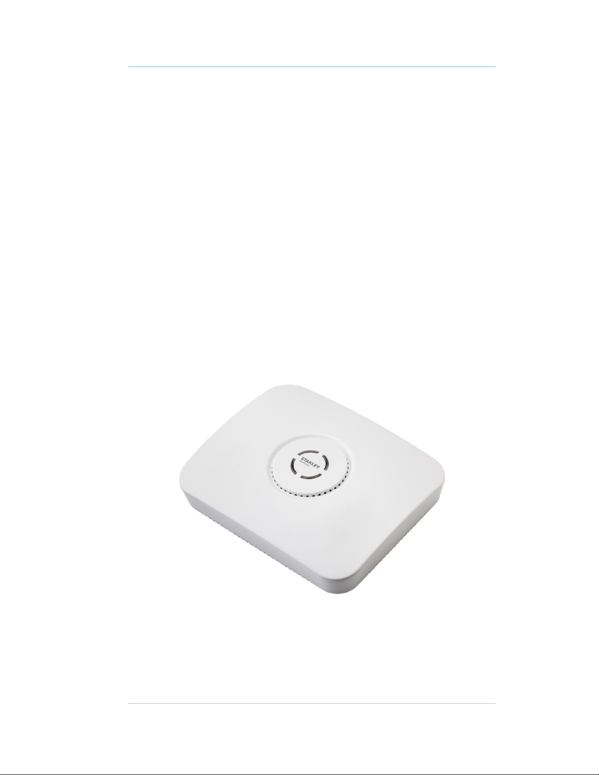
GW1200 Gateway
The GW1200 Gateway is a component of STANLEY Healthcare’s suite of solutions based
on Wi-Fi technology, enabling hospital-wide protection of patients and infants.
The Gateway is a 2.4 GHz receiver. It receives transmission messages from Hugs Wi-Fi
Tags and relays the messages to the Location Engine.
The Gateway is used to help provide the core layers of protection – Exit, Tamper, Tag
Loose and Supervision – in either a “Gateway only” deployment with a dedicated
network of Gateways providing Wi-Fi receiver coverage; or with strategically placed
Gateways augmenting the facility’s existing network of Access Points in the desired
protected areas.
The Gateway may also be incorporated with additional use cases as determined by
STANLEY Healthcare Engineering.
NOTE: The relay outputs are for future functionality and are not currently supported
within MobileView Hugs.
Figure 1: GW1200 Gateway
4
Page 5

GW1200 Gateway Installation & Configuration Guide
GW1200 Features
Wi-Fi Device Detection & Locator
The GW1200 Gateway contains two Wi-Fi transceivers for receiving Wi-Fi messages from
802.11 b/g/n (2.4 GHz) Hugs Wi-Fi Tags. Received messages are sent to the AeroScout
Location Engine for processing.
Network connectivity
The device supports remote programming, monitoring, and software updates by the
AeroScout Location Engine.
Continuous Gateway Supervision
The GW1200 Gateway device status is monitored at all times by the AeroScout Location
Engine. MobileView generates an alert if communication with the Gateway is
compromised.
Additionally, to provide full device supervision capabilities the receiver modules in the
Gateway will switch into a “test transmission mode” simulating Tag message
transmission, to verify reception of each other if no AeroScout tag messages are
received within a 60 second period.
Monitoring of Wi-Fi Receivers
The GW1200 Gateway constantly supervises the functionality of its two Wi-Fi receivers.
5
Page 6
GW1200 Gateway Installation & Configuration Guide
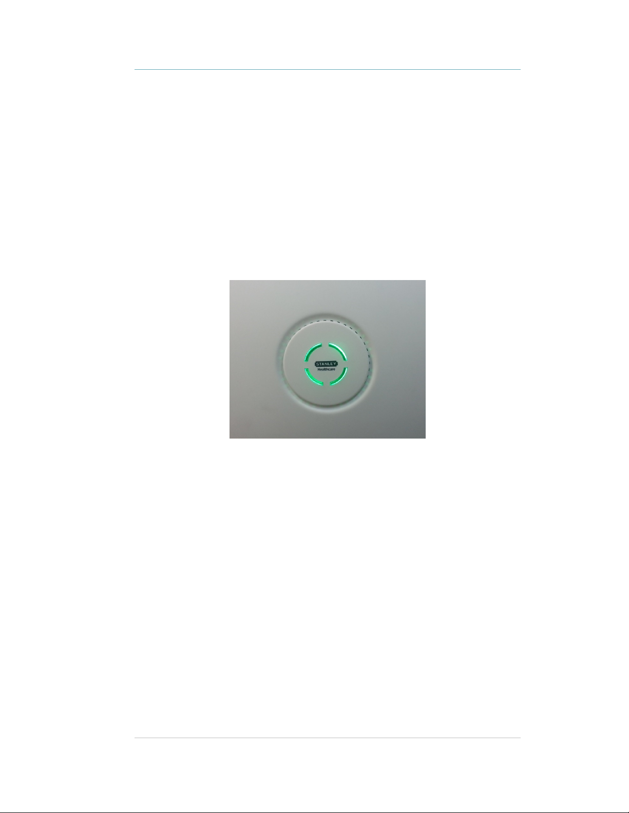
LED Status Indicators
The GW1200 Gateway has a single LED that changes color based on the device status as
follows:
•
Constant Green: The Gateway is on and working correctly
•
Constant Orange: Gateway failure or network down
•
No LED indication: Gateway is off
Figure 2: GW1200 Gateway LED Indicator
6
Page 7
GW1200 Gateway Installation & Configuration Guide
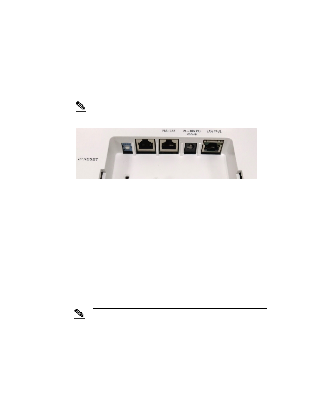
Connector Panel
The GW1200 Gateway has three connectors on the connector panel.
Note
(#1) Ethernet LAN Connection: RJ-45 connector. In a configuration with a physical
Ethernet cable connection to the LAN, the network cable is attached here.
The GW1200 supports 100 Mb Full duplex communications. The Ethernet Network
Switch must be configured to Auto Negotiation mode for the Gateway to operate at 100
Mb.
(#2) Power Jack: Accepts an input voltage of 24-48V DC. This is a standard 5 mm (outer)
2.5 mm (internal) jack connector for direct power supply. A power adapter is not
supplied with the Controller and can be purchased separately. When PoE is used, this
connector becomes redundant.
When both PoE and external power supplies are used the external power source
is the primary power source.
(#3) IN/RS-232 and OUT/RS-232 Connector: RJ-45 connector. RS-232 is used as a
console interface with the Exciter Manager Application (to change the IP address, for
example). For this option, a special 10-pin RJ45 to DB9 serial cable (AeroScout PN
40031500000) is required.
(#4) IP Reset: Restores the Gateway's IP address to the factory default value.
Inputs and Outputs are currently not in use.
Note
7
Page 8
GW1200 Gateway Installation & Configuration Guide
Network and Power
Connections to the GW1200
Gateway
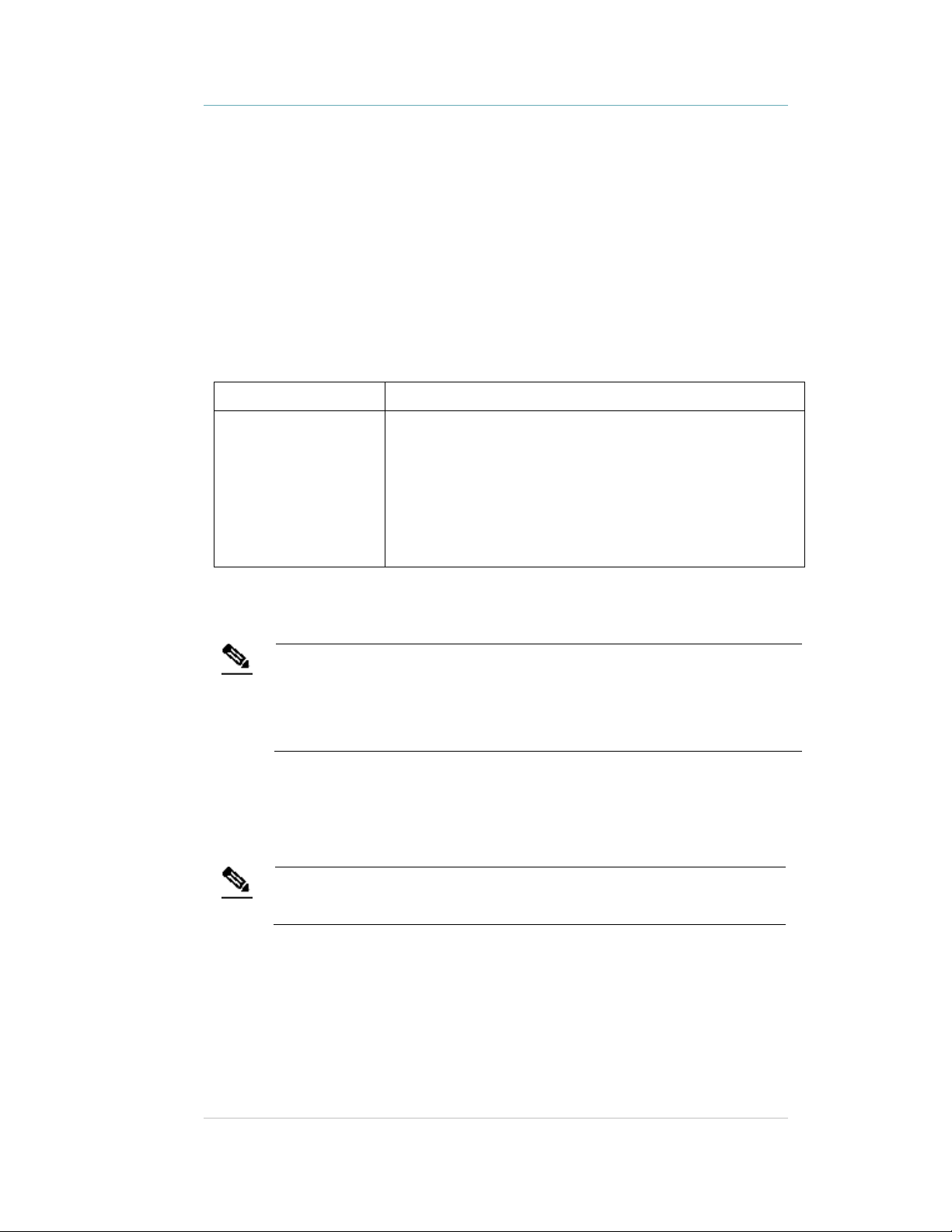
The following is a summary of available power and network options:
Usage Option Description
Single GW1200
Gateway – connected
to a network
Direct Power Supply
Connect a 24 to 48 VDC power source direct to the Gateway’s power jack.
The GW1200 requires approximately 8 W of power. When connecting a Gateway to a
Note
PoE Switch
If the network has a Power-over-Ethernet infrastructure, a CAT-5/6 Ethernet cable
connects the PoE switch to the Gateway’s LAN connector. This supplies both the power
and the network connection.
direct power source with one of the above options, verify that the provided power
level is sufficient.
The device must only be powered by a limited (marked LPS or NEC class 2) power
supply.
GW1200s can be remotely controlled (for configuration and
monitoring purposes) via the local area network. In this case,
connect it to both a power source and the network.
GW1200’s support power-over-Ethernet (PoE), which
supplies both power and network services via a single
connection.
Power options are 24-48V or PoE.
PoE standard 802.3af class 0 allows power for a single GW1200 Gateway.
Note
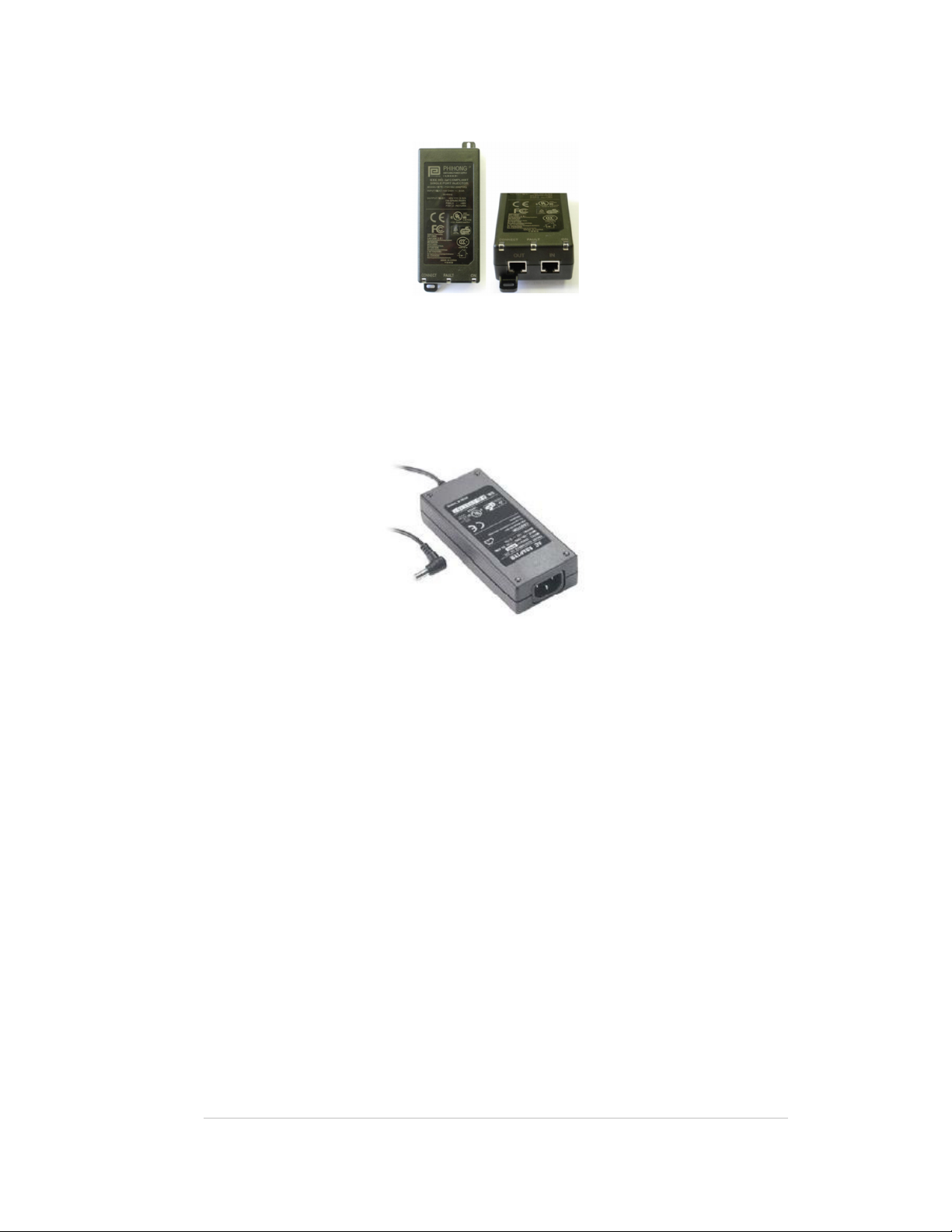
110/220 VAC to 48 VDC PoE Single-Port Injector
The PoE Single Port Injector converts 110/220 VAC to 48 VDC and permits connecting a
single cable from the network to the Gateway’s LAN connector, thus supplying both
power and network connectivity.
8
Page 9
GW1200 Gateway Installation & Configuration Guide
When using this injector, the Gateway power jack is not used.
Figure 3: 110/220 VAC to 48VDC PoE Single-Port Injector
The injector’s IN connector is connected to the network. The injector’s OUT connector is
connected to the Gateway’s LAN connector.
110/220 VAC to 48 VDC Power Supply Adapters
These adapters convert 110 VAC or 220 VAC to 48 VDC.
Figure 4: 110/220 VAC to 48 VDC Adapter
The adapter is connected to the GW1200 Gateway power jack. The network must be
connected separately to the Gateway LAN connector.
9
Page 10
GW1200 Gateway Installation & Configuration Guide
60
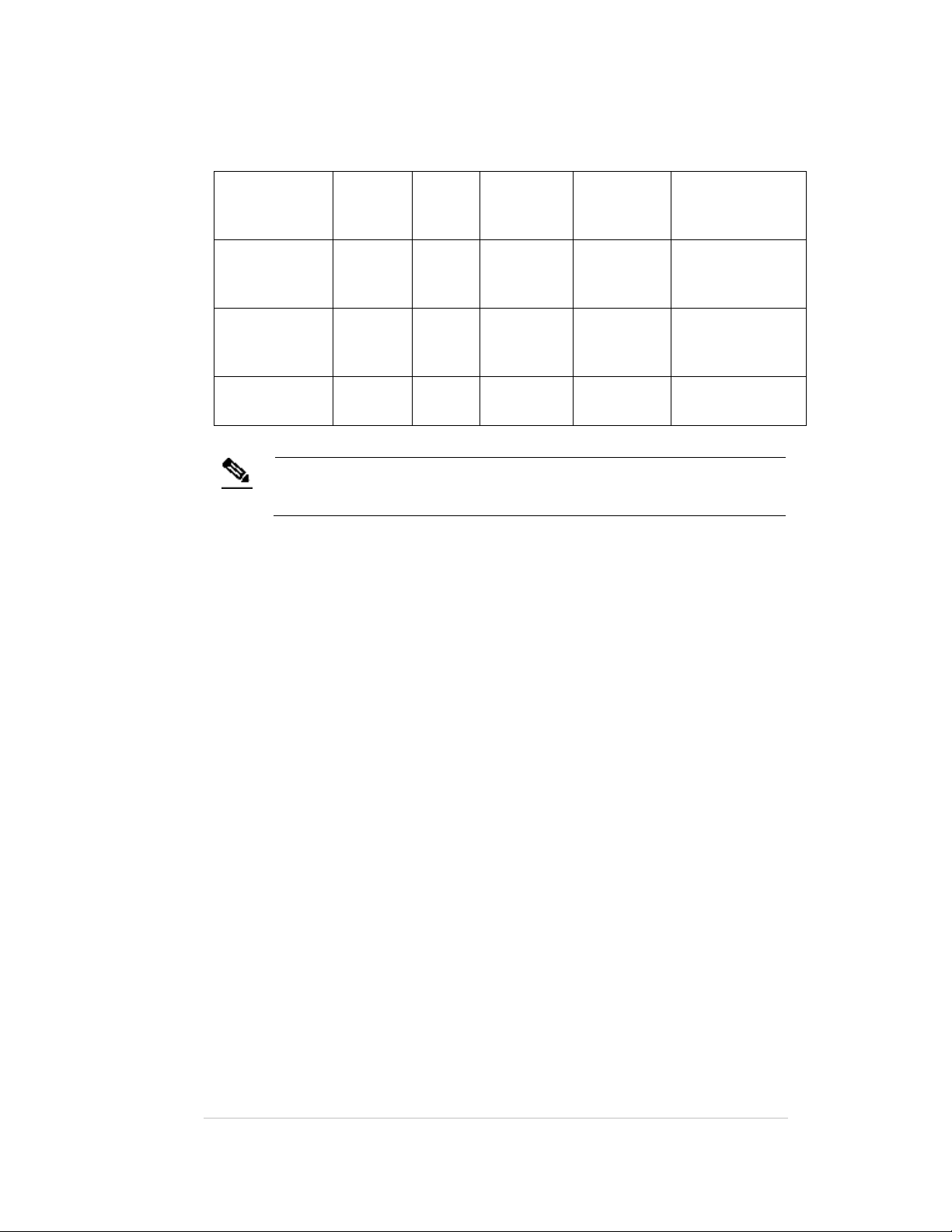
Power Connection Summary
The following table summarizes the power connection options:
Power Supply Input Output Max.
PoE single port
injector
100-240
VAC, 50-
48 VDC 0.32 A(1) 15.4 W One GW1200
Hz
Standard PoE
– 48 VDC 0.32 A(1) 15.4 W One GW1200
802.3af switch
port (2)
External power
– 48 VDC > 0.4 A > 20 W One GW1200
adapter
To prevent excessive power loss, PoE cables must not exceed 100 m (330’) in
length.
Note
Current
Available
Power
Maximum # of
Exciters with One
Source
Gateway
Gateway
Gateway
10
Page 11
GW1200 Gateway Installation & Configuration Guide
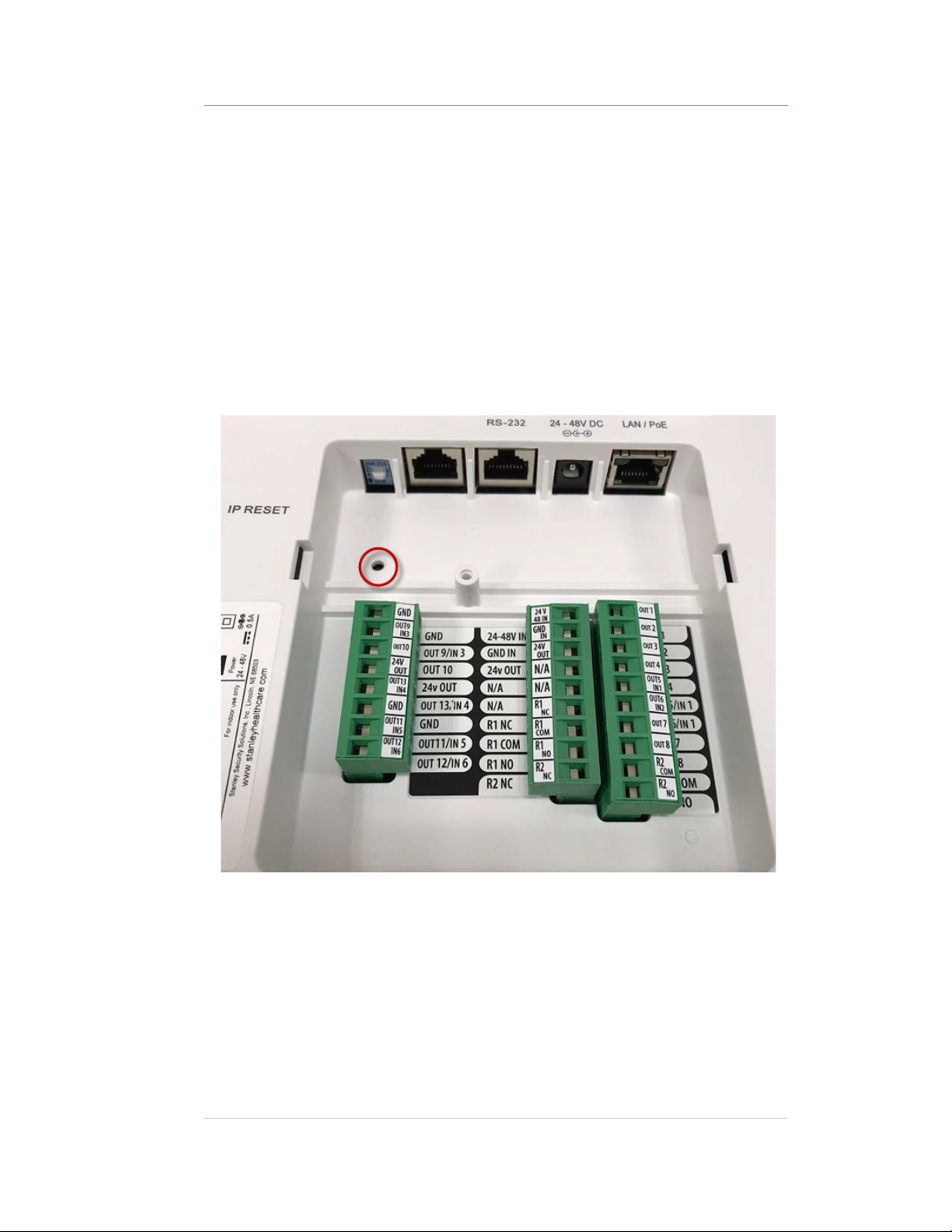
Resetting the GW1200
Gateway IP Address
The GW1200 Gateway IP address can be reset to the factory default value of
192.168.1.178. The Gateway does not support DHCP; requiring all device addresses to
be manually configured.
Press the IP Reset button with a ballpoint pen for at least 10 seconds.
Figure 5: IP Reset Button
11
Page 12

GW1200 Gateway Installation & Configuration Guide
GW1200 Naming Convention
In line with our recommended best practice, when configuring the GW1200 Gateways in
the AeroScout Location Engine, use recognizable names for the GW1200 Gateways as
the Gateway names are used in the alert distribution, and should provide clear
information for the alert location.
12
Page 13

GW1200 Gateway Installation & Configuration Guide
Adding & Configuring the
GW1200 via AeroScout Engine
Manager (AEM)
GW1200 Gateways are manually added and configured to appear on the map as an
Exciter.
Multiple Gateways can be added to the Location Engine using the Load Devices option
on the Repository tab, or the Scanning for Devices option after setting their IP addresses
and connecting them to the network.
For more information refer to the AeroScout Location Engine Deployment Guide –
Receivers section under Adding Receivers.
13
Page 14

GW1200 Gateway Installation & Configuration Guide
Updating Firmware –
Gateways
Updating the Firmware of GW1200 Gateways is performed in the Engine Manager. For
more information refer to the AeroScout Location Engine Deployment Guide – Upload
Exciter Firmware section.
14
Page 15

GW1200 Gateway Installation & Configuration Guide
Mounting the Gateway
Position and mount each GW1200 Gateway according to the site survey
recommendations.
Fixing the Controller to a Floating
Ceiling:
Mounting on a Wide grid with Flush Tiles
For this mounting option no mounting kit is required. Attach the device to the false
ceiling using the ceiling mounts located on the bottom casing of the device
1. Align the Mounting clips with the wide grid.
2. Twist and click the Exciter into place.
15
Page 16

Figure 6: Correct Complete Mounting Position
Mounting Off-Grid
GW1200 Gateway Installation & Configuration Guide
For this mounting option the following parts from the Heavy Duty, Off Grid, Exciter
Mounting
Part
kit (EXAC-HDUTY-1000) are required:
Part Name Quantity Image
Letter
A Mounting Adaptor 1
E ¼” x 3” Phillips Screw 2
G ¼” Hex Nut 6
I ¼” Spring washer 2
H ¼” Flat washer 2
D Bracket 512HD 1
16
Page 17

GW1200 Gateway Installation & Configuration Guide
1. Cut the Mounting Adaptor (A) so that only Section # 1 remains.
Use Mount Adaptor part marked with “<= 1 =>”
2. Step 2 – Fasten 2 Screws (E) on the 512HD Bracket (D) with 1 Flat Washer (H) and 1
Spring Washer (I). Set the distance between the Screws using the Adaptor (A).
3. Drill 2 holes* in the designated for installation ceiling tile for the Screws (E). Use the
assembled 512HD Bracket (D) to mark the location of the holes.
* Holes should be 5/16” or 8mm in diameter
17
Page 18

GW1200 Gateway Installation & Configuration Guide
4. Mount the Assembled 512HD Bracket (D) on the tile. Fix in place 2 Nuts (G) on each
of the Screws (E) leaving enough screw length (2/5” or 10mm) to mount the
Adaptor.
5. Mount the Adaptor using 2 Nuts (G) using a 7/16” nut driver.
6. Mount the Exciter onto the Adaptor (A) on the ceiling tile.
18
Page 19

GW1200 Gateway Installation & Configuration Guide
Figure 7: Correct Complete Mounting Position
19
Page 20

GW1200 Gateway Installation & Configuration Guide
Mounting on a Narrow-Grid T-Bar
For this mounting option the following parts from the Standard Exciter Mounting kit
(EXAC-STD-1000) are required:
Part Letter Part Name Quantity Image
A Mounting Adaptor 1
C Narrow Grid Clip- 9/16”
2
Clip with #8 Stud
J #8-32 Hex Nyloc Nut 2
1. Cut the Mounting Adaptor (A) so that only Section # 1 remains.
Use Mount Adaptor part marked with “<= 1 =>”
2. Assemble the Grid Clips (C) on the Adaptor (A). Lock each Clip (C) with Hex Nut (J).
The
Nuts should be loose at this stage to allow easy insertion onto the grid.
20
Page 21

GW1200 Gateway Installation & Configuration Guide
3. Attach the Grid Clips (C) with Mount Adaptor (A) onto the ceiling grid. (Push the
clips against the grid and twist them until they lock) (turn clockwise).
4. Fasten the Adaptor (A) to the Clips (C) by tightening Nuts (J) into their final position
using a 11/32" Nut Driver.
5. Mount the Exciter onto the Mounting Adaptor (A).
21
Page 22

GW1200 Gateway Installation & Configuration Guide
Figure 8: Correct Complete Mounting Position
22
Page 23

GW1200 Gateway Installation & Configuration Guide
Mounting on a Wide Grid with Recessed Tiles
For this mounting option the following parts from the Standard Exciter Mounting kit
(EXAC-STD-1000) are required:
Part Letter Part Name Quantity Image
A Mounting Adaptor 1
B Wide Grid Clip-15/16”
Clip with 1/4" Stud
G 1/4" Hex Nut 2
1. Cut the Mounting Adaptor (A) so that only Section # 1 remains.
2
Use Mount Adaptor part marked with “<= 1 =>”
2. Assemble the Grid Clips (B) on the Adaptor (A). Lock each clip (B) with Hex Nut (G).
Nuts should be loose at this step to allow easy insertion onto the grid.
23
Page 24

GW1200 Gateway Installation & Configuration Guide
3. Attach the Grid Clips (C) with Mount Adaptor (A) onto the ceiling grid. (Push the
clips against the grid and twist them until they lock). Fasten the Clip’s stud (B)
against the grid using a flat screwdriver (turn clockwise).
4. Tighten Nuts (G) to final position using a 7/16" Nut Driver.
5. Mount the Exciter onto the Mounting Adaptor (A).
24
Page 25

GW1200 Gateway Installation & Configuration Guide
Figure 9: Correct Complete Mounting Position
Mounting on a Slotted Grid
For this mounting option the following parts from the Standard Exciter Mounting kit
(EXAC-STD-1000) are required:
Part Letter Part Name Quantity Image
A Mounting Adaptor 1
F For Slotted Grid-
1/4"x0.625" Phillips
screw
G 1/4" Hex Nut 2
1. Cut the Mounting Adaptor (A) so that only Section # 1 remains.
2
25
Page 26

GW1200 Gateway Installation & Configuration Guide
Use Mount Adaptor part marked with “<= 1 =>”
2. Assemble the Screws (F) on the Adaptor. Lock each Screw (F) with Hex Nut (G)
*Nuts should be loose at this step to allow easy insertion into the slotted grid.
3. Mount the Adaptor (A) onto the Slotted-Grid by sliding the screw heads, Screw (F),
through the slots.
26
Page 27

GW1200 Gateway Installation & Configuration Guide
4. Fasten the Adaptor to the Screws (F) by tightening Nuts (G) to their final position
using a 7/16" Nut Driver.
5. Mount the Exciter onto the Mounting Adaptor (A).
Figure 10: Correct Complete Mounting Position
Mounting the Gateway on a Wall
While not normal practice, there may be occasions, particularly in older facilities where
the ceilings are already congested, when wall mounting of the GW1200 Gateway may be
the only viable option.
The Gateway is shipped with a mounting template which can be used to measure the
holes for mounting the Gateway on a wall. See Figure 11. The mounting plate supplied
with the Gateway is not required for wall mounting.
27
Page 28

GW1200 Gateway Installation & Configuration Guide
Figure 11: GW1200 Gateway mounting template (supplied with the Gateway)
1. Hold the template on the wall in the location you wish to mount the Gateway.
Make sure the template is level.
2. Mark the four holes for the screws through the template.
3. Remove the template.
4. Drill the holes for the screws.
5. Anchor the screws into the wall, leaving 10mm of each of the screws exposed. Use
appropriate screws and or anchoring plugs.
6. Mount the Gateway with the STANLEY Healthcare logo facing up, onto the 4 screws.
The Gateway's back panel has 4 mounting brackets for this purpose.
28
Page 29

GW1200 Gateway Installation & Configuration Guide
GW1200 and Accessories Model Numbers
Product SKU Description
GW1200
Gateway
Power Supply APD-047-U (US)
PoE Injector ADP-030-U (US)
Heavy Duty, Off
Grid, Exciter
Mounting Kit
Standard Exciter
Mounting Kit
GW-1200 GW1200 Gateway. Includes 48V DC input,
APD-047-E (Europe)
APD-047-UK (UK)
APD-047-J (Japan)
ADP-030-E (Europe)
ADP-030-UK (UK)
ADP-030-J (Japan)
EXAC-HDUTY-1000
EXAC-STD-1000
Ethernet and PoE interface
AC/DC adaptor 45W 48 V/1.0A 90-264VAC for
EX2000B, EX4200, EX5000, EX5200 Exciters,
EX5500 Controllers and GW1200 Gateways
PoE Power Injector for use with EX2000B,
EX3210, EX4200, EX5000, EX5200 Exciters and
GW1200 Gateways. 110/220VAC-48VDC.
Mounting Kit for mounting in the center of a
floating ceiling tile when mounting on the
ceiling grid is not possible or when heavy duty
mounting is required.
Fits the following Device Models: EX3210,
EX4100, EX4110, EX4200, EX5000, EX5200,
EX5500, External Speaker/Antenna, and
GW1200.
Each kit can be used for a single device.
Standard Exciter Mounting Kit for Exciters and
Gateways and off-grid mounting option for
External Antennas/Speakers
Supports recessed ceiling tiles and 3 types of
ceiling grids:
- 1" Ceiling Grid
- 1/2" Ceiling Grid
- Slot Grid
Fits the following Device Models: EX3210,
EX4100, EX4110, EX4200, EX5000, EX5200,
EX5500, External Speaker/Antenna, and
GW1200.
Off-grid mounting option is recommended for
External Exciters/Speakers and EX3210 Exciters
only
Each kit can be used for a single Exciter and
Gateway, or for two External Units.
29
Page 30

GW1200 Gateway Installation & Configuration Guide
GW1200 Specifications
Product Marketing Name (PMN)
•
GW1200 Gateway
Physical and Mechanical
•
Dimensions: 245 mm X 200 mm X 60 mm (9.6 in x 7.9 in x 2.4 in)
•
Weight: 865 g (31oz)
•
Housing: Polycarbonate and ABS
Network Interface
•
Ethernet (RJ-45)
•
Wi-Fi 802.11 b/g/n
Power
•
Input voltage: 24-48 VDC
•
PoE (802.3af) 48 VDC
•
Maximum power consumption: 10 W.
Environmental
•
Operating temperature: 0 to 50 °C (32°F to 122°F)
•
Humidity: 0 to 95%, non-condensing
30
Page 31

GW1200 Gateway Installation & Configuration Guide
FCC Part 15.105(b) Warning Statement
NOTE: This equipment has been tested and found to
comply with the limits for a
Regulatory Compliance &
Warranty
FCC
47 CFR Part 15, Class B Device
This device complies with part 15 of the FCC Rules. Operation is subject to the following
two conditions: (1) This device may not cause harmful interference, and (2) this device
must accept any interference received, including interference that may cause undesired
operation.
Changes or modifications not expressly approved by the party responsible for
compliance could void the user’s authority to operate the equipment.
Class B digital device, pursuant to part 15 of the FCC Rules. These limits are
designed to provide reasonable protection against harmful interference in a
residential installation. This equipment generates uses and can radiate radio
frequency energy and, if not installed and used in accordance with the
instructions, may cause harmful interference to radio communications. However,
there is no guarantee that interference will not occur in a particular installation. If
this equipment does cause harmful interference to radio or television reception,
which can be determined by turning the equipment off and on, the user is
encouraged to try to correct the interference by one or more of the following
measures:
- Reorient or relocate the receiving antenna.
- Increase the separation between the equipment and receiver.
-Connect the equipment into an outlet on a circuit different from that to which
the receiver is connected.
-Consult the dealer or an experienced radio/TV technician for help.
Industry Canada
31
Page 32

GW1200 Gateway Installation & Configuration Guide
This device complies with Industry Canada license-exempt RSS standard(s). Operation is
subject to the following two conditions: (1) this device may not cause interference, and
(2) this device must accept any interference, including interference that may cause
undesired operation of the device.
Le présent appareil est conforme aux CNR d’Industrie Canada applicables aux appareils
radio exempts de licence. L’exploitation est autorisée aux deux conditions suivantes : (1)
l’appareil ne doit pas produire de brouillage, et (2) l’utilisateur de l’appareil doit accepter
tout brouillage radioélectrique subi, même si le brouillage est susceptible d’en
compromettre le fonctionnement.
RoHS
RoHS Directive – 2011/65/EU
CE Conformance
IEC 60601-1:2005/EN 60601-1:2006
Medical Electrical Equipment
IEC 60950-12005
ESTI EN 301 498-1:V2.1.1
ESTI EN 301 498-17:V3.1.1
Warranty
STANLEY Healthcare (“STANLEY”) Standard Warranty and Disclaimer
32
Page 33

GW1200 Gateway Installation & Configuration Guide
For STANLEY Healthcare AeroScout® Products (“Products”)
Limited Warranty and Disclaimer. STANLEY warrants that commencing from the date of
delivery to Customer and continuing for a period of one (1) year thereafter (the “Warranty Period”),
the hardware components of STANLEY Healthcare AeroScout® Products (the “Hardware”) will be
free from defects in material and workmanship under normal use subject to the terms hereof. The
date of shipment of the Hardware by STANLEY is set forth on the packaging material in which the
Hardware is shipped. This limited warranty extends only to the original user of the Hardware.
Customer's sole and exclusive remedy and the entire liability of STANLEY and its suppliers under
this limited warranty will be, at STANLEY’s or its service center's option, shipment of replacement
Hardware components within the Warranty Period or a refund of the purchase price if the Hardware
is returned to the party supplying it to Customer, if different than STANLEY, freight and insurance
prepaid. STANLEY replacement parts used in Hardware repair may be new or equivalent to new,
and STANLEY reserves the right to provide replacement Hardware components of similar form and
function, as long as the functionality is equal or better than Customer’s original Hardware
components. STANLEY’s obligations hereunder are conditioned upon the return of affected
Hardware in accordance with STANLEY’s then-current Return Material Authorization (RMA)
procedures. Notwithstanding the foregoing, the warranty for TAG Hardware specifically designated
for sterilization via autoclave or other sterilization methods shall have a warranty period of 350
sterilization cycles from the date of delivery; provided, however, that sterilization outside of
environmental specifications approved in any applicable user documentation voids all warranties.
Extended Warranty: STANLEY offers an extended warranty, for a fee, on AeroScout
products. Within the one (1) year of the standard warranty, additional warranty of two (2) years may
be purchased. Additional warranty years may only be purchased once within the first one (1) year,
or prior to warranty expiration. A maximum of three (3) total warranty years are available for
Hardware.
Exclusions: The warranty set forth above will not apply if the Hardware or the Product (i)
has been altered, except by STANLEY, (ii) has not been installed, operated, repaired, or maintained
in accordance with instructions supplied by STANLEY, (iii) has been subjected to abnormal physical
or electrical stress, misuse, negligence, or accident; or (iv) is provided for beta, evaluation, testing,
or demonstration purposes for which STANLEY does not receive a payment of purchase price or
license fee.
In addition, this warranty shall not cover the following:
• Batteries (other than DOA -Dead On Arrival).
• Plastics (including defects in appearance, cosmetics, decorative or structural items
including framing and non-operative parts).
• Tag Calibration.
• Expenses related to removing or reinstalling the Products.
• Defects or damage that result from the use of Non-STANLEY certified Products,
Accessories, Software or other peripheral equipment.
• Defects or damages resulting from service, testing, adjustment, installation, maintenance,
alteration, or modification in any way by any party other than STANLEY, or its authorized
service partners.
• All software contained in or otherwise part of STANLEY Healthcare AeroScout®
Products, which is covered by STANLEY’s separate software warranty contained in
the separate software license agreement with respect to such Products.
33
Page 34

GW1200 Gateway Installation & Configuration Guide
The warranty set forth above shall not be enlarged and no obligation or liability shall arise
out of STANLEY’s rendering of technical advice, facilities or service in connection with Customer's
purchase of the STANLEY Healthcare AeroScout® Products.
Except for the foregoing warranties, which shall be the exclusive warranties with respect to
any Products, STANLEY MAKES NO WARRANTY OR REPRESENTATION OF ANY KIND,
EXPRESS OR IMPLIED, WRITTEN OR ORAL, REGARDING INFORMATION GIVEN OR THE
PRODUCTS OR SERVICES SUPPLIED AND EXPRESSLY DISCLAIMS ALL EXPRESS AND
IMPLIED WARRANTIES, REPRESENTATIONS AND CONDITIONS, INCLUDING WITHOUT
LIMITATION ALL WARRANTIES AND CONDITIONS OF QUALITY, NON-INFRINGEMENT,
MERCHANTABILITY AND SUITABILITY OR FITNESS FOR A PARTICULAR PURPOSE TO
THE EXTENT PERMITTED BY LAW. STANLEY WILL NOT BE LIABLE FOR CONSEQUENTIAL,
INCIDENTAL, INDIRECT OR PUNITIVE DAMAGES FOR ANY CAUSE OF ACTION, WHETHER
IN CONTRACT, TORT OR OTHERWISE. Consequential, incidental and indirect damages
include, but are not limited to, lost profits, lost revenue and loss of business opportunity,
whether or not STANLEY was aware or should have been aware of the possibility of these
damages.
34
Page 35

About STANLEY Healthcare
STANLEY Healthcare provides over 5,000 acute care hospitals and 12,000 long-term care organizations with enterprise
solutions that create a safe, secure and efficient healthcare experience across life’s stages. The STANLEY Healthcare
solution set enables customers to achieve organizational excellence and superior care in critical areas:
Patient/Resident Safety, Security & Protection, Environmental Monitoring, Clinical Operations & Workflow and Supply
Chain & Asset Management. These solutions are complemented by STANLEY Healthcare’s By Your Side™ Lifetime
Customer Care commitment to ensure that every customer achieves success and realizes the full value of their
investment, through consulting, training, implementation and integration services. STANLEY Healthcare is proud to be
part of Stanley Black & Decker, Inc. For more information, visit stanleyhealthcare.com. Follow STANLEY Healthcare on
Facebook, Twitter, LinkedIn and YouTube.
STANLEY Healthcare
130 Turner Street
Building 3
Waltham, MA 02453
Tel: +1-888-622-6992
North America
E-mail: stanleyhealthcare@sbdinc.com
Asia-Pacific
E-mail: stanleyhealthcare-asiapac@sbdinc.com
Europe
E-mail: shs-uk@sbdinc.com
Latin America
E-mail: stanleyhealthcare-latam@sbdinc.com
Middle East
E-mail: stanleyhealthcare-MEA@sbdinc.com
 Loading...