

Page 1

AeroScout EX5100 Exciter
User’s Guide
EX5100-UG-040313-02
Page 2

Disclaimer
The information and know-how included in this document are the exclusive property of AeroScout Inc.
and are intended for the use of the addressee or the user alone. The addressees shall not forward to
another their right of using the information, know-how or document forwarded herewith, in whole or
in part in all matters relating or stemming from or involved therein, whether for consideration or
without consideration, and shall not permit any third party to utilize the information, know-how or the
documents forwarded herewith or copies or duplicates thereof, unless at the company’s consent in
advance and in writing. Any distribution, advertisement, copying or duplication in any form
whatsoever is absolutely prohibited. The Company reserves the right to sue the addressee, user
and/or any one on their behalves, as well as third parties, in respect to breaching its rights pertaining
to the intellectual rights in particular and its rights of whatever kind or type in the information, knowhow or the documents forwarded by them herewith in general, whether by act or by omission.
This document is confidential and proprietary to AeroScout Inc. and is not to be distributed to any
persons other than licensed AeroScout Visibility System users or other persons appointed in writing
by AeroScout Inc.
Trademark Acknowledgements
AeroScout™ is a trademark of AeroScout, Inc. Other brand products and service names are
trademarks or registered trademarks of their respective holders. Below is a partial listing of other
trademarks or registered trademarks referenced herein:
Cisco™ is a trademark of Cisco Systems, Inc.
Sun, Sun Microsystems, the Sun Logo, Java, JRE and all other Sun trademarks, logos, product names,
service names, program names and slogans that are referred to or displayed in this document are
trademarks or registered trademarks of Sun Microsystems, Inc. in the United States and other
countries.
This product includes software developed by the Apache Software Foundation
(http://www.apache.org/).
This product includes code licensed from RSA Data Security
Esper is a trademark of EsperTech, Inc.
Jboss is a trademark of Red Hat Middleware, LLC.
Oracle 10G and Oracle 11G are registered trademarks of Oracle Corporation and/or its affiliates.
MS SQL Server 2005 and MS SQL Server 2008 are registered trademarks of Microsoft Corporation in
the United States and/or other countries.
JasperSoft, the JasperSoft Logo, JasperReports, the JasperReports logo, JasperIntelligence,
JasperDecisions, JasperAnalysis, Scope Center, Scope Designer, and JasperServer are trademarks or
registered trademarks of JasperSoft, Inc. in the United States and other countries.
Images of PLUM A+™, PLUM A+™ 3, LIFECARE PCA™, and SYMBIQ™ infusion systems are provided
with permission of Hospira, Inc. All rights reserved.
Copyright ©2011 AeroScout Inc. All rights reserved.
Page 3

AeroScout EX5100 Exciter
Table of Contents
Introduction ......................................................................................................................... 4
Application and Industry Examples ................................................................................ 5
EX5100 Features .................................................................................................................. 5
EX5100 Hardware ............................................................................................................... 6
Connecting the EX5100 to the Network and Power Source ....................................... 10
Chaining Exciters .............................................................................................................. 15
Resetting the EX5100 ........................................................................................................ 18
Exciter Configuration ....................................................................................................... 18
Mounting the Exciter ....................................................................................................... 23
EX5100 and Accessories Model Numbers ..................................................................... 24
EX5100 Specifications ....................................................................................................... 25
Appendix A. Slave Exciter Configuration Tool ........................................................... 27
Safety and Warnings ........................................................................................................ 31
Table of Contents 3
Page 4
AeroScout EX5100 Exciter
Introduction
The AeroScout EX5100 Exciter is a component of the AeroScout suite of enterprise
visibility solutions that enables location-based applications. The EX5100 extends the
AeroScout suite to provide robust and sophisticated RFID detection capabilities,
using the same AeroScout tags that can also be accurately located in real time by the
AeroScout system.
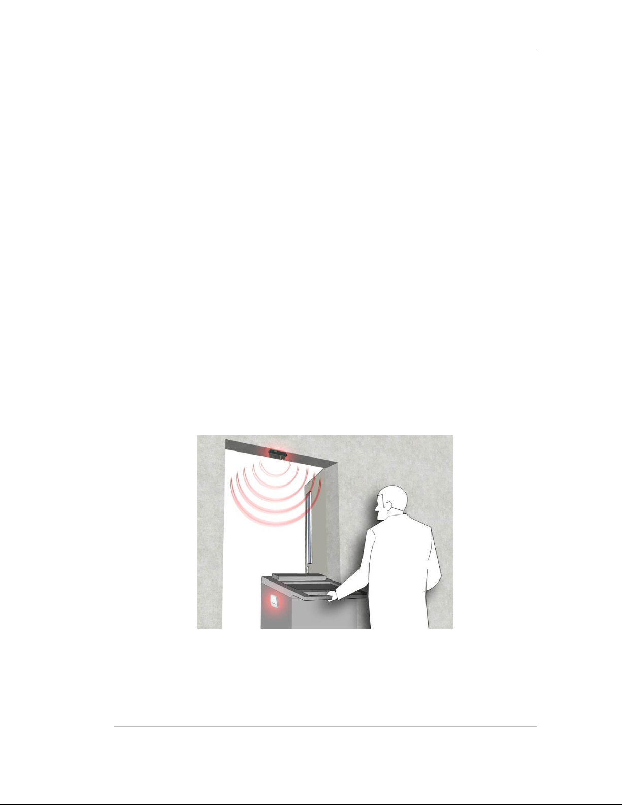
The EX5100 triggers AeroScout’s tags as they pass through a choke point or when
they are located near the Exciter and the tags in turn transmit Wi-Fi message to
Internal Receiver or compatible Access Points in range. The Exciter can
activate/deactivate the tags, program the tags or even cause tag reaction such as
blinking. This provides instant acknowledgment that a tagged asset passed through
a gate, doorway or some other well-defined area.
The EX5100 Exciter has built in Wi-Fi receiver which enables it to receive AeroScout
tag messages. The Exciter also has an embedded Wi-Fi transmitter which is utilized
by the Exciter for self-health monitoring. These capabilities make the Exciter ideal for
security applications.
The detection capabilities of the EX5100, combined with the location features of the
AeroScout Visibility System, make the AeroScout suite the most sophisticated
enterprise visibility solution for a wide variety of industries.
Figure 1: EX5100 positioned at choke point triggering a tag
Introduction 4
Page 5

AeroScout EX5100 Exciter
Note
The exciters’ effective range, based on specific environment and
placement, may be less than the configured range. The effective range
should be taken into consideration when planning and designing the
deployment.
Application and Industry Examples
High value asset tracking
Health care facilities and general enterprises can tag valuable assets that are
intended to stay within a certain area. The AeroScout system can track the location
of those assets, and if they leave through an exit or enter a restricted area, the EX5100
triggers a tag message.
Process control
Manufacturing and supply chain facilities can track the location and presence of
equipment and in-process inventory as it moves through the production process.
This gives an enterprise a real-time view of which (and how many) assets have
passed each step in the process, enabling better supply chain management.
Inventory management
Logistics and manufacturing enterprises can automatically update inventory records
as inventory enters and leaves the warehouse, ensuring real-time knowledge of
levels without manual checks or physical scanning.
Security applications
Government agencies and enterprises can tag secure assets and people that are
restricted to certain areas or require historical location tracking. If those assets leave
through an exit or enter a restricted area, EX5100 triggers a tag message.
EX5100 Features
RFID detection of AeroScout Tags
Triggering the tags to transmit as they pass through a defined area, EX5100s reach
up to a 6.5 meters (21.3 ft) range, enough to cover typical door or gate areas. EX5100s
can also be chained one to another, thus increasing the RFID detection range for
accommodating even very large areas.
Application and Industry Examples 5
Page 6

AeroScout EX5100 Exciter
Tag behavior modification:
The EX5100 can wirelessly active and deactivate tags. Tag battery life can be
extended further by switching the tags off when they leave a defined tracking area
through a gate or doorway.
It is also possible to configure the Exciter to change of tag transmission rate
temporarily or indefinitely to accommodate different usage patterns in various
physical spaces.
Message Programming functions
The EX5100 has the ability to store messages on the tag for later transmission.
Message transmission can later be triggered by other EX5100s, enabling
sophisticated process control functions.
EX5100 can trigger a tag to:
transmit up to 15 bytes of data sent to it by the EX5100;
transmit one of 15 pre-stored messages;
transmit and store up to 15 bytes of data sent to it by the EX5100.
Network connectivity
Enables remote programming, monitoring and software updates by the AeroScout
Engine. In addition, the EX5100 can work in offline mode disconnected from the
network, thus eliminating the need for a physical network feed. In this mode, remote
configuration and monitoring is not enabled.
EX5100 Hardware
The AeroScout EX5100 includes the following components:
125 KHz LF Tx
Bidirectional Wi-Fi module with only the receiver enabled
Wi-Fi transmitter (T2 Tag) which is used by the exciter for health
management.
Exciter controller
EX5100 Hardware 6
Page 7

Figure 2: AeroScout EX5100
AeroScout EX5100 Exciter
EX5100 Hardware 7
Page 8
AeroScout EX5100 Exciter
1 2 3 4 5 6 7 1 2
3
LED Indications
Top panel LED
Figure 3: EX5100 LED indicators
Green LED constantly lit indicates that the unit is connected to a power
source but not transmitting, or it is in slave mode and not transmitting.
Blinking Green LED (according to transmission interval) indicates that the
EX5100 is transmitting LF (Low Frequency) signals.
Green LED constantly lit when the unit is connected to a power source.
Orange LED represents Link (LAN Connection)
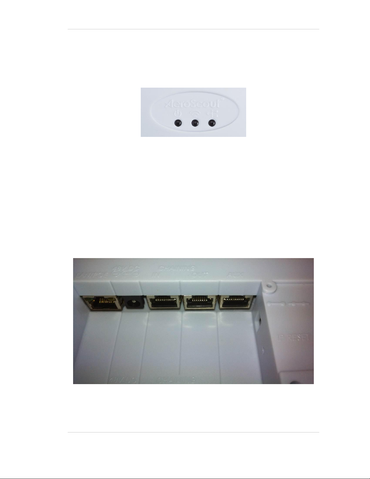
Connectors Panel
Figure 4 displays the EX5100 connector panel.
Figure 4: AeroScout EX5100 Connectors
EX5100 Hardware 8
Page 9

AeroScout EX5100 Exciter
WARNING: The auxiliary connection is for connecting an External Speaker
unit only. Connecting other devices or a POE connection to the auxiliary
input may harm the Exciter.
1. Ethernet LAN Connection – RJ-45 interface. In a configuration that uses a physical
Ethernet cable connection to the LAN, the network cable is attached here. Permanent
connection to a wired network is not mandatory. However you must have a wired
connection for configuring the Exciter. In addition, some of the monitoring functions
will not be available if the Exciter is not wired. This connection is also used for
Power over Ethernet (PoE, 802.3af).
2. Power jack – Accepts an input voltage of 48V DC. This is a standard 2.5mm jack
connector for direct power supply. Alternatively, you can use the power supply that
is packaged along with the Exciter. When PoE is used, this connection is not used.
3. Chain IN Connector – RJ-45 connector. This connector is used for receiving power
from chained Exciters.
4. Chain OUT and Control Connector – RJ-45 connector. This connector is used for
distributing power to chained Exciters. The output voltage is 12V DC (0.5A
maximum).
5. Auxiliary connector – Designed for connecting an External Speaker unit.
6. Termination Switch – For defining termination settings in a chained Exciters
installation. The default factory setting is Termination On (o-o). In chained Exciters
installations, the termination of the first and last Exciters in the chain should be set to
On (o-o) and the rest should be set to Off (-o-o-).
7. IP Reset Switch: Restores the device’s IP address to the company default.
EX5100 Hardware 9
Page 10

AeroScout EX5100 Exciter
Usage
option
Description
Single
EX5100
– not
connect
ed to
network
EX5100s can be used as standalone devices that function independently
without any network connection. In this case, you need to connect the
EX5100 to the power supply only. Using System Manager, set the control
switch to EXT, and set the unit to be “not connected to the network".
Single
EX5100
–
connect
ed to
network
EX5100s can be remotely controlled (for configuration and monitoring
purposes) through the local area network. In this case, you need to
connect it to both a power source and the network.
AeroScout EX5100s also support power-over-Ethernet (PoE), which
supply both power and network services via a single connection. Set the
control switch to EXT.
Connecting the EX5100 to the Network and
Power Source
The following is a brief summary of available powering and networking options:
Connecting the EX5100 to the Network and Power Source 10
Page 11

Usage
option
Description
Chained
EX5100
s – not
connect
ed to
network
EX5100s can be connected to each other in a chain and receive
the power/data from one master EX5100 in the chain. This
configuration does not require any network connectivity. Up to 8
EX5100s can be connected in a chain. Up to 3 EX5100s can use
the same power source (depending on the source’s power). See
Direct Power Supply
Directly connect a 48VDC power source to the Exciter’s power jack
(connector 2 in Error! Reference source not found.).
Note
An Exciter requires approximately 10W of power. When
connecting an Exciter to a direct power source with one of
the above voltage levels, verify that the current level is
sufficient.
When using a direct power source for chained Exciters,
you can drive power to no more than three Exciters
sequentially even if the source power is sufficient for
more.
Unit shall be powered only by limited power source
(marked LPS or NEC class 2) power supply.
PoE Switch
If your network has a Power-over-Ethernet infrastructure, you can
connect a CAT-5 Ethernet cable from the PoE switch to the Exciter’s
LAN connector (connector 1 in Error! Reference source not found.).
This supplies both the power and the network connection.
Note
PoE standard 802.3af class 0 allows power for not more
than one Exciter. When using PoE with chained Exciters, a
PoE connection must be made to every single Exciter in
the chain. In addition, the LAN connectivity that the PoE
supplies will not be utilized for slave Exciters in a chain.
110/220 VAC to 48VDC PoE Single-Port Injector
The PoE Single Port Injector converts 110/220VAC to 48VDC. In
addition, it can receive a network connection and enable the installer to
run a single cable to the Exciter’s LAN connector, thus supplying both
power and network connectivity.
When using this injector, the power jack of the Exciter will not be used.
AeroScout EX5100 Exciter
Chaining Exciters 11
Page 12

AeroScout EX5100 Exciter
Note
An Exciter requires approximately 10W of power. When connecting an
Exciter to a direct power source with one of the above voltage levels,
verify that the current level is sufficient.
When using a direct power source for chained Exciters, you can drive
power to no more than three Exciters sequentially even if the source
power is sufficient for more.
Unit shall be powered only by limited power source (marked LPS or NEC
class 2) power supply.
Note
PoE standard 802.3af class 0 allows power for not more than one
Exciter. When using PoE with chained Exciters, a PoE connection must
be made to every single Exciter in the chain. In addition, the LAN
connectivity that the PoE supplies will not be utilized for slave Exciters
in a chain.
Direct Power Supply
Directly connect a 48VDC power source to the Exciter’s power jack (connector 2 in
Error! Reference source not found.).
PoE Switch
If your network has a Power-over-Ethernet infrastructure, you can connect a CAT-5
Ethernet cable from the PoE switch to the Exciter’s LAN connector (connector 1 in
Error! Reference source not found.). This supplies both the power and the network
connection.
110/220 VAC to 48VDC PoE Single-Port Injector
The PoE Single Port Injector converts 110/220VAC to 48VDC. In addition, it can
receive a network connection and enable the installer to run a single cable to the
Exciter’s LAN connector, thus supplying both power and network connectivity.
Chaining Exciters 12
Page 13

AeroScout EX5100 Exciter
Note
An injector can provide enough power for one Exciter only. When using
the injector with chained Exciters, an injector must be connected to
every single Exciter in the chain. In addition, the LAN connectivity that
the injector supplies, is not to be utilized for slave Exciters in a chain.
When using this injector, the power jack of the Exciter will not be used.
Figure 5: Single-Port Injector
The injector’s IN connector is connected to the network. The injector’s OUT
connector is connected to the Exciter’s LAN connector (connector 1 in Error!
Reference source not found.).
The injector can be used for both networked and non-networked Exciters. In case of
a non-networked Exciter, the IN connector on the injector is not used.
110VAC/220VAC to 48VDC Power Supply Adaptors
These adaptors convert 110VAC or 220VAC inputs to 48VDC
Chaining Exciters 13
Page 14

AeroScout EX5100 Exciter
Power supply
Input
Output
Maximum
Current
Available
Power
Maximum #
of Exciters
with one
source
POE single port
injector
100-240V
AC 50-60Hz
48VDC
0.32A
(1)
15.4W
1
Standard POE
802.3af switch
port
(2)
-
48VDC
0.32A
(1)
15.4W
1
External power
source
-
48VDC
>1A
>48W
3
(3)
Note
Cable losses are included assuming cables are less than 100m long.
The POE class should be 0. The Exciter port cannot support power
required by more than three Exciters.
Figure 6: 110VAC to 48VDC or 220VAC to 48VDC Adaptor
The adaptor is connected to the Exciter’s power jack). The network should be
connected separately to the Exciter’s LAN connector (connector 1 in Error! Reference
source not found.). This adaptor is most common for chained Exciters. It can be used
for supplying power to up to three Exciters.
Power Connection Summary
The following table summarizes the power connection options:
Chaining Exciters 14
Page 15

AeroScout EX5100 Exciter
Chaining Exciters
In an area where the required LF coverage exceeds the capacity of one Exciter, you
can chain several Exciters, thus extending the coverage area. For example, a large
entrance gate for trucks and heavy equipment that is 10m wide might require three
Exciters chained to one another.
The chained EX5100s will be treated by the system as a single entity and as a single
Exciter with a single ID covering a larger area. Transmissions will not interfere with
one another.
The EX5100s’ transmission ranges and physical positions should be set in a manner
that will allow overlapping between neighboring EX5100s’ coverage areas.
Figure 7 illustrates chained EX5100s and shows the connections.
Figure 7: EX5100 chaining
Chain Connection
Up to 8 EX5100s can be connected to each other in a chain, as follows:
6. The first Exciter in the chain that is directly connected to the LAN is called the
“master”. The others are called “slave”. Any EX5100 can be a master or slave.
7. The master is connected to the next slave from the master’s OUT connector
(connector 4 in Figure 4) to the slave’s IN connector (connector 3 in Figure 4).
8. A slave is connected to the next slave in the same manner (from OUT to the next
slave’s IN).
Chaining Exciters 15
Page 16

AeroScout EX5100 Exciter
9. The Termination Switch (item 5 in Figure 4) of the master and the last slave in
the chain should be set to On (o-o).
On the other slaves, it should be set to Off ( -o o-).
10. The Master/Slave configuration is done using System Manager 4.3 or higher. If
you are using an older version of System Manager, the master-slave
configuration is done using the Slave Exciter Configuration Tool (SECT). See
Appendix A. Slave Exciter Configuration Tool.
The slaves will inherit the master's ID and its LF configurations aside from the
transmission range.
Figure 8: Slave configuration in System Manager
Chaining Exciters 16
Page 17

AeroScout EX5100 Exciter
Chaining an EX3210 Exciter
To connect the EX3210 Exciter to the EX5100 Exciter, follow these steps:
1. The EX5100 Exciter in the chain that’s directly connected to the PoE/LAN is
called the “master”. The EX3210 Exciter is also a “master”. Each Exciter has its
own ID.
2. Configure the EX3210 Exciter as not connected to the network.
3. Connect the EX3210 Exciter to the Chain Out connector of the EX5100 Exciter.
Power Connection Considerations
As mentioned earlier, an external power supply or AC/DC adaptor can support up
to three chained Exciters, and a PoE connection can support one Exciter. In order to
chain more Exciters than the currently connected power supply can feed, an
additional power supply element can be added using a junction box.
Figure 9: Junction box
1. Connect the junction box to its power supply.
2. Connect the last of the currently connected slave’s OUT to the junction box’s IN.
3. Connect the junction box’s OUT to the next slave’s IN.
4. Connect subsequent slaves to each other as explained above.
If necessary, you can use more than one junction box to supply more power along
the chain.
Chaining Exciters 17
Page 18

AeroScout EX5100 Exciter
Resetting the EX5100
You can reset the EX5100’s IP address to the factory defaults by pressing the IP Reset
button using a thin, pin-like object. The Reset button is located on the LAN side of
EX5100. The default IP address is 192.168.1.178. After a successful IP reset the red
LED will lit for two seconds.
Figure 10: IP Reset button
Exciter Configuration
Exciters are configured using the AeroScout System Manager or MSE. The
configuration settings consist of device installation and network definitions.
Configuring the Exciter via System Manager
The configuration procedure involves the following steps:
1. Connect all Exciters with a wired Ethernet connection to a dedicated segment.
2. Add the Exciters with the AeroScout System Manager, configure their
parameters and define their IP settings (The preconfigured IP is supplied per
Exciter).
If you wish to later change the IP settings (IP, subnet, gateway or ports) you can
do so by right-clicking on the Exciter and selecting IP Settings.
3. Check that the Exciter’s status is OK by right clicking on the Exciter icon and
selecting Status. Also verify in the status window that the firmware versions
(DSP and Second Boot) are compatible with the current installed Engine version
Resetting the EX5100 18
Page 19

AeroScout EX5100 Exciter
and Exciter hardware version. Consult AeroScout Support regarding the
appropriate firmware versions.
4. Position the Exciter in the site according to site survey recommendations, and
mount it.
5. Align the Exciters’ positions according to the required area coverage.
6. If you wish to define the Exciter as an offline Exciter not connected to the
network, you should approve the above configuration, wait for a confirmation,
define the Exciter as disconnected from network from the Properties window,
approve the settings again and disconnect the Exciter from the network.
For more information please refer to the AeroScout Engine User’s Guide.
Configuring the Exciter via MSE
The configuration procedure involves the following steps:
1. Open the WCS and select Configure, Chokepoints.
Figure 11: Exciter configuration in MSE
2. Select Add Chokepoint.
Exciter Configuration 19
Page 20

AeroScout EX5100 Exciter
Figure 12: Adding Chokepoint
3. Enter the Exciter MAC address, name, static IP address, and click the Save
button.
4. Select Monitor, Maps and then the relevant campus, building and floor.
Figure 13: Exciter configuration in MSE
5. Select Add Chokepoint and click Go.
Exciter Configuration 20
Page 21

AeroScout EX5100 Exciter
Figure 14: Exciter configuration in MSE
6. Check the relevant Exciters and click OK.
7. You will be switched back to the relevant floor area.
8. Locate the added Exciter on the map and click Save.
9. Select Services, Synchronize Services and synchronize the relevant MSE.
10. Open System Manager and configure the Exciter.
Figure 15: System Manager configuration - Settings
11. On the left panel select the Internal LF entry and configure it.
Exciter Configuration 21
Page 22

AeroScout EX5100 Exciter
Note
Starting from Engine version 4.3, master-slave configuration is done
using System Manager. Use the Slave Exciter Configuration Tool (SECT)
for earlier versions.
Figure 16: System Manager configuration – Internal LF
For more configuration options and the relevant use cases, please refer to the
AeroScout Exciter Deployment Guide.
Exciter Configuration 22
Page 23

AeroScout EX5100 Exciter
Mounting the Exciter
Mounting the Exciter to a floating ceiling:
Attach the device to the false ceiling by the ceiling mounts which are located on the
bottom panel of the unit.
Figure 17: Exciter mounting brackets
Mounting the Exciter on a Wall
Mount the Exciter with the AeroScout logo facing up.
Fix the Exciter on the wall using four screws threaded through the four holes at the
back of the casing.
Mounting the Exciter 23
Page 24

AeroScout EX5100 Exciter
Product
SKU
Description
EX5100
Exciter
EX-5100
EX5100 Exciter. Includes 48V DC input, Ethernet and
PoE interface
EX5100
Power Supply
ADP-047
AC/DC adaptor 45W 48V/1.0A 90-264VAC.
Exciter
Detector Tool
EXD-1000
Tool for visualization of the effective LF Exciter
transmission field. Analyzes the Exciter coverage during
deployment. Includes a PC application and the detector
hardware that can be connected via USB to a PC.
EX5100 and Accessories Model Numbers
EX5100 and Accessories Model Numbers 24
Page 25

AeroScout EX5100 Exciter
EX5100 Specifications
Physical and Mechanical
Dimensions: 180 x 155 x 45 mm (7.1in x 6.1in x 1.8in)
Weight: 450g (16oz)
Housing: Polycarbonate
Coverage
Adjustable coverage range up to 6m (19.6ft) by intervals of 0.5m (1.6ft)
LF Channel
125kHz
Field intensity limits: 37.3dBµA/m at 10m (ETSI)
Propagation limits: 21.8dBµV/m at 300m (FCC)
Modulation: ASK
Network Interface
Ethernet (RJ-45)
Power
Input voltage: 48VDC
PoE (802.3af) 48VDC
Maximum power consumption: 10W.
Environmental
Operating temperature: 0 to 50 °C (32°F to 122°F)
Humidity: 0 to 95%, non-condensing
Certifications
EMC Certifications
US standard: FCC part 15
European standard: ETSI 300.328, 300.330, ETSI 301.489
Canada: RSS 210
EX5100 Specifications 25
Page 26

EMC standard for healthcare: IEC 6100 / EN 60601
Japan : ARIB per demand
Australia : C-tick per demand
Korea : MIC per demand
Safety Certifications
US – cTUVus: UL 60950
Europe – CE mark: EN 60950
AeroScout EX5100 Exciter
EX5100 Specifications 26
Page 27

AeroScout EX5100 Exciter
Note
Starting from AeroScout Engine version 4.3, the tool is part of the
Engine.
Appendix A. Slave Exciter Configuration Tool
This appendix describes the Slave Exciter EX5100 Configuration Tool, which is
designed to configure Exciters EX5100 as slaves in a chained Exciter configuration.
Installation
To install the tool, run "AeroScout Slave Exciter EX5100 Configuration Tool.msi" and
follow the instructions displayed on the screen.
Activation
1. If AeroScout Engine or AeroScout Network Exciter Manager is installed, stop
the corresponding services.
2. Launch the tool.
Its main window appears.
Figure 18: Activation – Single Exciter
Appendix A. Slave Exciter Configuration Tool 27
Page 28

AeroScout EX5100 Exciter
Configuring a Single Exciter
The computer’s IP address should be in the same subnet as the Exciter.
1. Connect the Exciter to the same LAN as the computer running the tool.
2. Under the Single Exciter tab, enter the Exciter’s IP address.
3. If, before configuring it, you want to check whether the Exciter is in working
order, click the Check Status button.
4. Do one of the following:
If you wish to modify the Exciter’s range while configuring it, select the Use
new info radio button and click the Retrieve button. The value appears in the
Range fields. If necessary, change the Range values.
This operation also retrieves the Phase value. The phase should not be
changed unless instructed so by AeroScout Support.
If you want to keep the values already configured (set via AeroScout System
Manager or AeroScout Network Exciter Manager), select the Use
preconfigured phase and range radio button.
5. Click the Configure to Slave button.
It is assumed that the listening port of the Exciter is the default 1511. If the port was
changed, it should be restored to 1511 (using AeroScout System Manager or
AeroScout Network Exciter Manager).
Configuring Multiple Exciters
This section explains how to configure multiple EX5100 Exciters in a single
operation.
The computer IP address should be in the same subnet as the Exciters.
1. Connect the Exciters to the same LAN as the computer running the tool.
2. Select the Multiple Exciters tab.
Appendix A. Slave Exciter Configuration Tool 28
Page 29

AeroScout EX5100 Exciter
Figure 19: Activation – Multiple Exciters
3. In the List of Exciters IP addresses type the IP address of the Exciters to
configure.
You can separate the IP addresses with any of the following characters: commas,
spaces, semicolons (;), tabs.
4. To check whether the Exciters are in working order, click the Check Status
button.
The tool returns a report specifying the Exciters that have responded and those
that have not responded. For the latter, the type of failure. The report also lists
the illegal IP addresses, if any.
5. If you wish to modify the Exciters’ range, select the Use new info radio button
and type the value in the Range field. All of the Exciters included in the
operation will be set to the range you entered.
The phase should not be changed unless instructed so by AeroScout Support.
If you want to keep the values already configured (using AeroScout System
Manager or AeroScout Network Exciter Manager), select the Use preconfigured
phase and range.
6. Finally, to configure the Exciters as slaves, click the Configure to Slave button.
The tool returns a report specifying the Exciters that have been configured and
those that have not been configured. In the latter case, the type of failure is
indicated. The report also lists the illegal IP addresses, if any.
Appendix A. Slave Exciter Configuration Tool 29
Page 30

AeroScout EX5100 Exciter
It is assumed that the listening port of the Exciter is the default 1511. If the port was
changed, it should be restored to 1511 (using AeroScout System Manager or
AeroScout Network Exciter Manager).
Appendix A. Slave Exciter Configuration Tool 30
Page 31

AeroScout EX5100 Exciter
Safety and Warnings
FCC STATEMENT
This equipment has been tested and found to comply with the limits for a Class B
digital device, pursuant to Part 15 of the FCC rules. These limits are designed to
provide reasonable protection against harmful interference in a residential
installation. This equipment generates, uses and can radiate radio frequency energy
and, if not installed and used in accordance with the instructions, may cause harmful
interference to radio communications. However, there is no guarantee that
interference will not occur in a particular installation. If this equipment does cause
harmful interference to radio or television reception, which can be determined by
turning the equipment off and on, the user is encouraged to try to correct the
interference by one or more of the following measures:
a) Reorient or relocate the receiving antenna.
b) Increase the separation between the equipment and receiver.
c) Connect the equipment to an outlet on a circuit different from that to which the
receiver is connected.
d) Consult the dealer or an experienced radio/TV technician.
This device complies with Part 15 of the FCC Rules.
Operation is subject to the following two conditions:
a) This device may not cause harmful interference
b) This device must accept any interference received, including interference that may
cause undesired operation.
Safety and Warnings 31
Page 32

AeroScout EX5100 Exciter
WARNING: This device complies with Part 15 of the FCC Rules and RSS-210 of Industry and
Science Canada. Operation is subject to the following two conditions: (1) This device may not cause
harmful interference, and (2) this device must accept any interference received, including
interference that may cause undesired operation.
This device complies with Industry Canada license-exempt RSS standard(s). Operation is subject to
the following two conditions: (1) this device may not cause interference, and (2) this device must
accept any interference, including interference that may cause undesired operation of the device.
Le présent appareil est conforme aux CNR d'Industrie Canada applicables aux appareils radio
exempts de licence. L'exploitation est autorisée aux deux conditions suivantes : (1) l'appareil ne
doit pas produire de brouillage, et (2) l'utilisateur de l'appareil doit accepter tout brouillage
radioélectrique subi, même si le brouillage est susceptible d'en compromettre le fonctionnement.
FCC Warning
Modifications not expressly approved by the manufacturer could void the user
authority to operate the equipment under FCC Rules.
Safety and Warnings 32
Page 33

About AeroScout
AeroScout is the market leader in Unified Asset Visibility solutions. Clients improve operational
efficiency and quality using AeroScout products that leverage standard Wi-Fi networks to track and
manage the location, condition and status of mobile assets and people. AeroScout’s global customer
base consists of leading hospital, manufacturing and logistics organizations, including many of the
Fortune 500. The company originally invented the first Wi-Fi-based Active RFID tag, and today is
widely recognized as leading the market in number of deployments and tags shipped. Headquartered
in Redwood City, Calif., AeroScout has offices in Europe, Asia, the Middle East, Latin America and
Australia. For more information, please visit www.aeroscout.com.
AeroScout (Headquarters)
1300 Island Drive
Suite 202
Redwood City, CA 94065
Tel: +1 (650) 596-2994
Fax: +1 (650) 596-2969
E-mail: info@aeroscout.com
Europe, Middle East, Africa Office
Tel : +32 2 709 29 49
Fax : +32 15 30 80 99
E-mail: emea@aeroscout.com
Japan Office
Tel: +81 3 3556 9003
Fax: + 81 3 5875 3723
E-mail: info@aeroscout.co.jp
Latin America Office
Tel : +52 55 5001 5769
E-mail: latam@aeroscout.com
Asia-Pacific Sales
Tel : +1 650 596 2994
E-mail: apac@aeroscout.com
Australia and New Zealand Sales
Tel : +61 3 9038 8690
E-mail: anz@aeroscout.com
 Loading...