

Page 1
Hugs® Wi-Fi Tag Charger
User Guide
Page 2

Page 3

Table of Contents
Introduction 1
Overview 1
Model Numbers 1
Intended Use 1
Safety Considerations 1
Documentation 1
Orientation 2
General Description 2
Operating and Display Modes 5
Installing the Charger 6
Wall Mounted 6
Setting Up the Charger 7
Using the Charger 8
Inserting the Tag into the Charger 8
Removing the Tag from the Charger 9
Specific Charging Capabilities 10
Overview 10
Dimensions and Weight 10
Hugs Tags States 11
Hugs Tag Behavior with Sensor Alarm 12
Hugs® Wi-Fi Tag Charger User Guide
iii
Page 4

Maintenance 13
Operational Checks 13
Cleaning Instructions 13
Supplies and Accessories 15
Compliance and Safety 16
iv
Hugs® Wi-Fi Tag Charger User Guide
Page 5

Introduction
Introduction
Overview
The Hugs on MobileView software notifies the users when the Hugs Tag
battery is getting low. Placing the Hugs Tag in the charger erases all the
history data from the tag, including the Kisses® bonding and the tag
status. It also triggers MobileView to erase the specific patient admitting
information.
Model Numbers
The Hugs Tag Charger part number:
• CGS-HGS-1000
Based on the power supply outlet type:
• CGS-HGS-1000-U U.S. outlet
• CGS-HGS-1000-E European outlet
• CGS-HGS-1000-J Japanese outlet
• CGS-HGS-1000-UK U.K. Outlet
Intended Use
The Hugs Wi-Fi Tag Charger is intended for facility staff who are using the
Hugs Wi-Fi Tags in conjunction with the MobileView security application.
Safety Considerations
• Position any trailing wires so that they are not a trip hazard and are less
likely to get damaged.
• Check that the plug is not damaged and that the cable is properly
secured with no internal wires visible.
• Where there is evidence that the supply may not be safe, such as
damaged equipment or wiring, the supply should not be used until work
has been done to correct this.
Documentation
Please refer to the following document for technical specifications for the
Hugs Wi-Fi Tag Charger.
• Hugs Wi-Fi Tag Charger Data Sheet p/n 0971-063-000
Hugs® Wi-Fi Tag Charger User Guide
1
Page 6
Orientation
Orientation
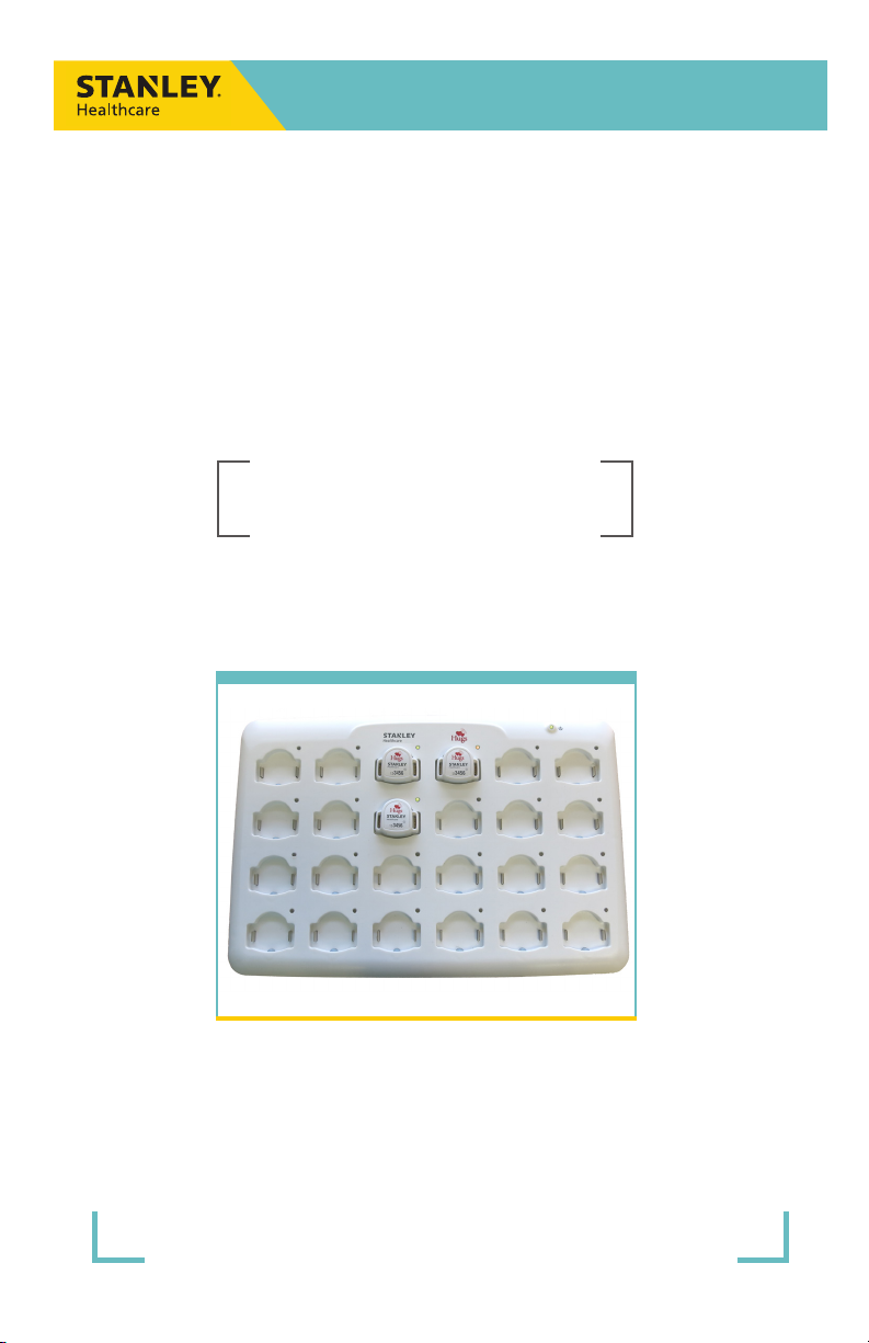
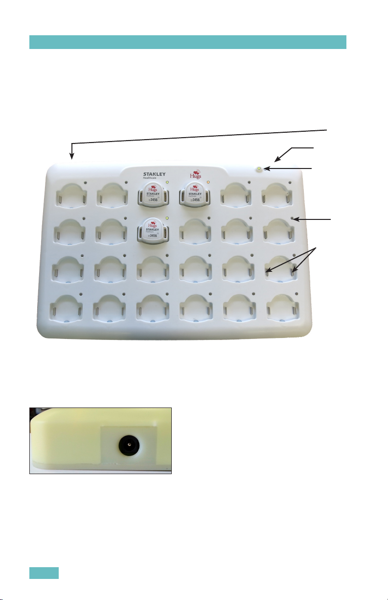
General Description
This section describes the parts and LEDs on the Charger.
POWER
SOCKET
ON/OFF
SWITCH
CHARGER
STATUS
CHARGING
LED
CHARGING
METALS
Power Socket
The power socket is located at the top-left side of the Charger. An external
power supply is provided with the Charger. For more information about the
power supply, see “Supplies and Accessories” on page 15.
2
Hugs® Wi-Fi Tag Charger User Guide
Page 7
Orientation
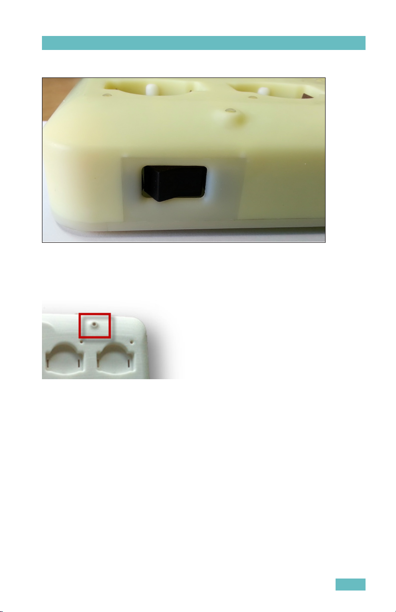
ON/OFF Switch
After the Charger is plugged in, press the ON/OFF switch to the ON position.
When the Charger is not being used, press the switch to the OFF position.
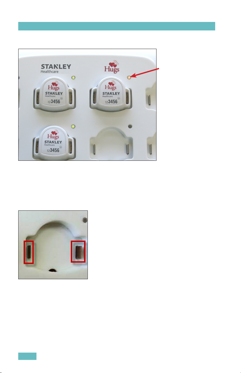
Charger Status LED
The Charger status LED is located at the top-right on the front of the
Charger. When the Charger is plugged in and turned on, the Charger status
LED turns YELLOW.
Hugs® Wi-Fi Tag Charger User Guide
3
Page 8
Orientation
Charging LED for Hugs Tag
CHARGING LED:
Yellow when the Hugs Tag
is correctly placed in the
Charger
Each Hugs Tag impression in the Charger has its own charging LED (24
LEDs in total). There are three (3) available colors for the LEDs: GREEN,
YELLOW and RED. For more information about the LED color indications, see
“Operating and Display Modes” on page 5.
Charging Metals
The charging metals are located on either side of the inside of the Hugs Tag
impression. Charging for the Hugs Tag only begins once the charging metals
are in contact with the metal in the tag slots
4
Hugs® Wi-Fi Tag Charger User Guide
Page 9

Orientation
Operating and Display Modes
The following table describes the LED indications for the Hugs Tag Charger.
Color Description
GREEN Battery is fully charged.
YELLOW Charging in progress.
RED FLASHING Issue with the Hugs Tag. Remove and replace the tag.
RED SOLID
OFF - NO COLOR LED is does not turn on when the tag is placed in the slot– Remove
YELLOW Located near the ON/OFF switch indicating the Charger is ON.
Issue with the Charging slot. It is not necessary to unplug the
Charger. An error may possibly be cleared by switching the
Charger OFF then back ON again. If the issue continues, do not
use the specic Charging slot. Other slots can be used for charging.
Please contact Support.
the tag and replace it with a dierent tag. If the LED is still o, place
the tag in another charging slot. If the LED is on (GREEN or AMBER) in
the new slot then the problem is with the rst charging slot. Do not
use this slot to charge tags. If the LED in the new charging slot is o
as well, then there is an issue with the tag. Discard the tag.
Hugs® Wi-Fi Tag Charger User Guide
5
Page 10

Installing the Charger
Installing the Charger
The following items are included with the Hugs Tag Charger:
• two (2) #6 Philips head screws
• two (2) plastic wall anchors
• Mounting plate
Wall Mounted
1. Establish a location on the wall for the Hugs Tag Charger.
2. Draw two (2) holes on the wall, at a level distance 262 mm apart,
from center to center.
3. Drill two holes at the marked locations on the wall.
4. Insert the plastic wall anchors in the drilled holes.
5. Mount the plate and align the anchor holes with the wall anchors.
6. Using the supplied Philips head screws, securely screw the plate to
the wall.
7. Optionally, use wood screws or other suitable wall mount hardware
in the remaining holes on the plate.
8. Slide the Hugs Tag Charger onto the plate to mount it on the wall.
6
Hugs® Wi-Fi Tag Charger User Guide
Page 11

Setting Up the Charger
Setting Up the Charger
1. Plug the supplied power cable into the power socket located on the
side of the Charger.
2. Plug the other end into the wall external outlet (at least 12VDC @
3A).
3. Press the ON/OFF switch to the ON position.
4. The Charger status LED turns YELLOW indicating that the Charger is
now ready for use.
Hugs® Wi-Fi Tag Charger User Guide
7
Page 12

Using the Charger
Using the Charger
Inserting the Tag into the Charger
1. Ensure the Hugs Tag is clean to prevent contamination to the
Charger.
2. Aim the bottom of the Hugs Tag towards the small bump located in
the inferior portion of the tag impression in the Charger.
3. Push the tag and align the band slots to the charging metals.
8
Hugs® Wi-Fi Tag Charger User Guide
Page 13

Using the Charger
4. Push down firmly to insert the tag into the impression.
5. The status LED turns YELLOW, indicating that the Hugs Tag is now
charging.
Removing the Tag from the Charger
1. Push the tag towards the small bump and lift the tag out of the
impression.
Hugs® Wi-Fi Tag Charger User Guide
9
Page 14

Specific Charging Capabilities
Specific Charging Capabilities
Overview
The battery charging process does not harm the Hugs Tag or its operational
characteristics.
Charging the Hugs Tags that are connected (up to 24 units) to the Charger
takes approximately 3 hours. Once charged, the Hugs Tag can be used for
approximately 2 weeks. It is, however, recommended to place the Hugs Tag
in the Charger between uses (ensure the tag is thoroughly cleaned first!).
The Charger updates (through an LF command) each of the tags “in charger”
current battery capacity. This update is performed in steps of 5-10% until
fully charged (100%).
The Charger transmits the following information to the tag:
• Charger ID
• Slot #
• Battery charging status
• Date/time
• Tag MAC address
Note: The Charger is mechanically built to prevent tags from being inserted
in the wrong direction.
Dimensions and Weight
• Size: 300 x 250 x 100 mm
• Weight: 1 kg (not including the tags which by themselves can weigh 1 kg)
10
Hugs® Wi-Fi Tag Charger User Guide
Page 15

Hugs Tags States
State Description
Dormant • Initial state after manufacturing
• When the tag is not in use
In-Charger When the Hugs Tag is placed in the charger:
• The Kisses bond information is automatically cleared.
• A Hugs Tag In-charger mode does not sense bands. Note: The
tag must be removed from the charger to allow insertion of a
band.
• Three Wi-Fi messages (assuming the tag has enough battery
to transmit these messages) are transmitted indicating that the:
- Hugs Tag is in the charger
- Bonding status is erased
- Hugs Tag is asleep
The Hugs Tags exit charging mode and enters into normal sleep mode when
they are removed from the Charger (even if they are not fully recharged).
Normal
Sleep
Active
- Band
Connected
Active
Alarm -
Band Cut
Sleep Alarm
- Band Cut
Hugs® Wi-Fi Tag Charger User Guide
• When the tag is not in use
• Kisses ignored
• When it is ready to be activated
• When it can be connected to a Charger
• The Hugs Tag is on a baby
• Able to bond in accordance to the bonding status:
- Able to bond
- Bonded
- Not bonded (unable to bond)
• Kisses accepted
During a alarm from the band being cut, the following is true for the
Hugs Tag:
• The tag is NOT on a baby
• The tag is able to bond in accordance to the bonding status:
- Able to bond
- Bonded
- Not bonded (unable to bond)
• Kisses accepted. Band can be reconnected
• Can be connected to Charger
When the Hugs Tag alarms during sleep mode, the following is true:
• The tag is NOT on baby
• Unable to bond
• Kisses ignored
• Band can be reconnected
• Can be connected to Charger
Hugs Tags States
11
Page 16

Hugs Tags States
Hugs Tag Behavior with Sensor Alarm
The Hugs tag handles alarms with a priority as follows:
1. LF Exciter message (Door Exciter or Kisses)
2. Tamper event
3. Kisses mismatch event
4. Standard Wi-Fi messages
5. Proximity event
6. Other event
12
Hugs® Wi-Fi Tag Charger User Guide
Page 17

Maintenance
Maintenance
Operational Checks
It is recommended to verify all LEDs are working by placing a Hugs Tag in
each of the impressions, at least once a week. If, at any time, an LED fails
to light up (even when you switch the Charger Off then On again), contact
Support.
Cleaning Instructions
The Hugs Tag Charger can be cleaned using a soft bristle brush. Follow these
guidelines for cleaning the Charger:
• First, consult with your Infection Control representative for cleaners
available to your hospital that have been approved for use on plastics.
• Use a disinfectant with no more than 20% alcohol or enzymatic cleaners
with a mild pH such as Enzol or Maxizyme.
• Do not use pathogenic cleaners specified for TB.
• Do not soak the Charger.
• Do not use an autoclave to clean the Charger or serious damage may
result.
Please refer to the table on the following page as a guideline for suggested
cleaning materials and their preparation amounts.
NOTE: Cleaning products are currently being tested on the Charger. This
document will be updated once the results are tabulated.
Hugs® Wi-Fi Tag Charger User Guide
13
Page 18

Maintenance
# Solution Manufacturer Preparation
1. Super Edisonite S. M. Edison Chem-
2. Vesphene® Iise Calgon Vestal Labo-
3. Manu-Klenz Calgon Vestal Labo-
4. Coverage™ HBV Calgon Vestal Labo-
5. Formula C™ Diversey Corpora-
6. Sporicidin® Sporicidin Interna-
7. Precise Caltech Per manufacturer's recommendation
8. Dimension III Butcher's 0.5 oz/gallon water
9. Expose II 256 Diversey Corpora-
10. LpH Disinfectant
Cleaner
11. Phenolic 256 DC Coastwide Lab 0.5 oz/gallon water
12. Thymocide Wexford Labs, Inc. 0.5 oz/gallon water
13. Asepti-zyme Huntington 1 oz/gallon water
14. Detergezyme Metrex 1 oz/gallon water
15. Maxima 128 Brulin 1 oz/gallon water
16. Metrizyme Metrex 1 oz/gallon water
17. Wexcide 128 Wexford Labs, Inc. 1 oz/gallon water
18. Professional Amphyl
Hospital Bulk Disinfectant Cleaner
19. Virkon DuPont 1.28 oz/gallon water
20. Wexcide-Ready-ToUse
21. Hibiclens 25.6 oz/gallon water
22. Staph-Attack Not Applicable
23. Compublend II (Base
V with fragrance)
24. Neutral QUAT
Disinfectant Cleaner
Concentrate
ical Co
ratories
ratories
ratories
tion
tional
tion
Steris 0.5 oz/gallon water
Reckitt Benckiser 1.28 oz/gallon water
Wexford Labs, Inc. Ready to use
3M
3M
Per manufacturer's recommendation
Per manufacturer's recommendation
Per manufacturer's recommendation,
(0.25 – 0.5 oz/gallon water)
Per manufacturer's recommendation
Per manufacturer's recommendation
Per manufacturer's recommendation
0.5 oz/gallon water
14
Hugs® Wi-Fi Tag Charger User Guide
Page 19

Supplies and Accessories
Supplies and Accessories
The Hugs Tag Charger is shipped with the following components:
• 110/220V AC (autoselect)
• External power supply: at least 12VDC @ 3A
• Power cable (3 meters*) replaceable and country-specific for the
following areas:
- Argentina
- Australia
- China
- Europe (except Italy, Switzerland, and United Kingdom)
- Italy
- Japan
- North America
- South Africa, United Arab Emirates, India
- South Korea
- Switzerland
- United Kingdom
• Folded base (for inclined standing option)
• Two (2) #6 Philips head screws
• Two (2) plastic wall anchors
• Mounting plate
*Note: In North America, AC power cords must not exceed 4.5 meters
(approximately 14.75 feet) in length, to comply with National Electrical Code
(NEC) Sections 400-8 (NFPA 75, 5-2.2) and 210-52 and Canadian Electrical
Code (CEC) Section 4-010(3).
Hugs® Wi-Fi Tag Charger User Guide
15
Page 20

Compliance and Safety
Compliance and Safety
• UL 60950
• EN 60950 - Directive – RTTE (1999/5/EC)
• LVD (2006/95/EC)
• UL STD 294
• IEC/EN 60601-1-3
• ISO 14971
• ROHS (Directive 2011-65-EU/EC)
Federal Communication Commission (FCC)
This equipment has been tested and found to comply with the limits for a Class
B digital device, pursuant to Part 15 of the FCC rules. These limits are designed
to provide reasonable protection against harmful interference in a residential
installation.
This equipment generates, uses and can radiate radio frequency energy and, if
not installed and used in accordance with the instructions, may cause harmful
interference to radio communications. However, there is no guarantee that
interference will not occur in a particular installation. If this equipment does
cause harmful interference to radio or television reception, which can be
determined by turning the equipment off and on, the user is encouraged to try
to correct the interference by one or more of the following measures:
1) Reorient or relocate the receiving antenna.
2) Increase the separation between the equipment and receiver.
3) Connect the equipment to an outlet on a circuit different from that to which
the receiver is connected.
4) Consult the dealer or an experienced radio/TV technician.
WARNING! Changes or modifications to this unit not expressly approved by
the party responsible for compliance could void the user’s authority to operate
the equipment.
This device complies with FCC Rules Part 15 and with Industry Canada
licence-exempt RSS standard(s). Operation is subject to two conditions: (1)
This device may not cause harmful interference, and (2) this device must
accept any interference that may be received or that may cause undesired
operation.
Le present appareil est conforme aux CNR d’Industrie Canada applicables
aux appareils radio exempts de licence. L’exploitation est autorisee aux
deux conditions suivantes: (1) l’appareil ne doit pas produire de brouillage,
et (2) l’utilisateur de l’appareil doit accepter tout brouillage radioelectrique
16
Hugs® Wi-Fi Tag Charger User Guide
Page 21

Compliance and Safety
subi, meme si le brouillage est susceptible d’en compromettre le
fonctionnement.
Hugs® Wi-Fi Tag Charger User Guide
17
Page 22

Compliance and Safety
18
Hugs® Wi-Fi Tag Charger User Guide
Page 23

Hugs® Wi-Fi Tag Charger User Guide
19
Page 24

About STANLEY Healthcare
STANLEY Healthcare provides over 5,000 acute care hospitals and 12,000
long-term care organizations with enterprise solutions that transform safety,
security and operational efficiency. The STANLEY Healthcare EcoSystem
enables customers to achieve organizational excellence and superior care
in five critical areas: Patient Safety, Security & Protection, Environmental
Monitoring, Clinical Operations & Workflow and Supply Chain & Asset
Management. These integrated solutions are complemented by consulting,
training and Transformational Lean™ process reengineering. STANLEY
Healthcare is proud to be part of Stanley Black & Decker, Inc.
For more information, visit www.stanleyhealthcare.com.
STANLEY Healthcare
130 Turner Street, Waltham, MA 02453
Phone: +1-888-622-6992
Email: stanleyhealthcare@sbdinc.com
© 2013 STANLEY Healthcare. All rights reserved. Doc Part # 0980-041-000 Rev 01. 07/2013.
 Loading...