

Page 1

AeroScout EX4200 Ultrasound
Exciter
User’s Guide
EX4200-UG-150712-11
Page 2

Disclaimer
The information and know-how included in this document are the exclusive property of AeroScout Inc.
and are intended for the use of the addressee or the user alone. The addressees shall not forward to
another their right of using the information, know-how or document forwarded herewith, in whole or
in part in all matters relating or stemming from or involved therein, whether for consideration or
without consideration, and shall not permit any third party to utilize the information, know-how or the
documents forwarded herewith or copies or duplicates thereof, unless at the company’s consent in
advance and in writing. Any distribution, advertisement, copying or duplication in any form
whatsoever is absolutely prohibited. The Company reserves the right to sue the addressee, user
and/or any one on their behalves, as well as third parties, in respect to breaching its rights pertaining
to the intellectual rights in particular and its rights of whatever kind or type in the information, knowhow or the documents forwarded by them herewith in general, whether by act or by omission.
This document is confidential and proprietary to AeroScout Inc. and is not to be distributed to any
persons other than licensed AeroScout Visibility System users or other persons appointed in writing
by AeroScout Inc.
Trademark Acknowledgements
AeroScout™ is a trademark of AeroScout, Inc. Other brand products and service names are
trademarks or registered trademarks of their respective holders. Below is a partial listing of other
trademarks or registered trademarks referenced herein:
Cisco™ is a trademark of Cisco Systems, Inc.
Sun, Sun Microsystems, the Sun Logo, Java, JRE and all other Sun trademarks, logos, product names,
service names, program names and slogans that are referred to or displayed in this document are
trademarks or registered trademarks of Sun Microsystems, Inc. in the United States and other
countries.
This product includes software developed by the Apache Software Foundation
(http://www.apache.org/).
This product includes code licensed from RSA Data Security
Esper is a trademark of EsperTech, Inc.
Jboss is a trademark of Red Hat Middleware, LLC.
Oracle and Java are registered trademarks of Oracle and/or its affiliates. Other names may be
trademarks of their respective owners.
MS SQL Server 2005 and MS SQL Server 2008 are registered trademarks of Microsoft Corporation in
the United States and/or other countries.
JasperSoft, the JasperSoft Logo, JasperReports, the JasperReports logo, JasperIntelligence,
JasperDecisions, JasperAnalysis, Scope Center, Scope Designer, and JasperServer are trademarks or
registered trademarks of JasperSoft, Inc. in the United States and other countries.
Images of PLUM A+™, PLUM A+™ 3, LIFECARE PCA™, and SYMBIQ™ infusion systems are provided
with permission of Hospira, Inc. All rights reserved.
Copyright 2010 AeroScout Inc. All rights reserved.
Page 3

AeroScout EX4200 Ultrasound Exciter
Table of Contents
Introduction ......................................................................................................................... 6
EX4200 Features .................................................................................................................. 7
EX4200 Hardware ............................................................................................................... 9
Connecting the Exciter to the Network and Power Source ........................................ 10
Chaining Exciters .............................................................................................................. 14
Connecting an External LF Unit ..................................................................................... 17
Connecting an External Speaker Unit............................................................................ 17
Attaching the External LF Antenna and External Speaker to a false/ acoustic
Ceiling ................................................................................................................................ 19
Attaching an External LF Antenna or an External Speaker to the Wall ................... 20
Exciter Configuration ....................................................................................................... 21
Mounting the Exciter ....................................................................................................... 26
Deployment Considerations ........................................................................................... 28
Ultrasound Exciter Hardware Components ................................................................. 30
Specifications ..................................................................................................................... 31
Safety and Warnings ........................................................................................................ 34
Limited Warranty ............................................................................................................. 35
Table of Contents 3
Page 4

AeroScout EX4200 Ultrasound Exciter
Table of Figures
Figure 1: AeroScout EX4200 Exciter .................................................................................... 6
Figure 2: AeroScout EX4200 Exciter Connectors Panel .................................................... 8
Figure 3: AeroScout EX4200 Exciter board ......................................................................... 9
Figure 4: HW Version indication on Aeroscout Exciters ................................................ 10
Figure 5: Single-Port Injector .............................................................................................. 12
Figure 6: 110VAC to 48VDC or 220VAC to 48VDC Adaptor ........................................ 13
Figure 7: Exciter chaining.................................................................................................... 14
Figure 8: Slave configuration in System Manager ........................................................... 15
Figure 9: External LF/Speaker unit .................................................................................... 17
Figure 10: AUX connector cover ........................................................................................ 18
Figure 11: External Antenna/ Speaker, IN connector and mounting brackets ............ 18
Figure 12: Mounting an External Unit to a false ceiling ................................................. 19
Figure 13: External Unit mounted on a false ceiling ....................................................... 20
Figure 14: Exciter configuration in MSE ........................................................................... 22
Figure 15: Adding Chokepoint........................................................................................... 22
Figure 16: Exciter configuration in MSE ........................................................................... 23
Figure 17: Exciter configuration in MSE ........................................................................... 23
Figure 18: System Manager configuration - Settings ...................................................... 24
Figure 19: System Manager configuration – Internal LF ................................................ 24
Figure 20: System Manager configuration –US Exciter .................................................. 25
Figure 21: Exciter Plate ........................................................................................................ 26
Figure 22: Exciter Plate removal ........................................................................................ 27
Figure 23: Ceiling mount..................................................................................................... 27
Figure 24: Exciter mounted on the ceiling ........................................................................ 27
Figure 25: Exciter deployment consideration .................................................................. 28
Figure 26: Multiple Exciter deployment consideration .................................................. 29
Document History 4
Page 5

AeroScout EX4200 Ultrasound Exciter
REVISION HISTORY
Revision
Date
Comments
Author
1
27 January 2010
New version
E Prigat
M Sharon
2
1 May 2010
Updates
E Prigat
3
3 May 2010
Updates
E Prigat
4
25 May 2010
Updates
E Prigat
5
7 July 2010
Updates
E Prigat
6
22 December 2010
Added: External LF and External
Speaker units.
E Prigat
M Sharon
7
26 January 2011
Added: Attaching the External LF
Antenna and External Speaker
E Prigat
M Sharon
8
10 August 2011
Updated: Master-Slave
R Blanca
M Sharon
9
7 September 2011
Added: Auxiliary connection cover
R Blanca
R Evenor
10
04 April 4, 2012
Added: New External Units
R Blanca
R Evenor
11
15 July 2012
Added: External Units specs
R Blanca
Document History 5
Page 6
AeroScout EX4200 Ultrasound Exciter
Introduction
The AeroScout EX4200 Ultrasound Exciter is a component of the AeroScout suite of
enterprise visibility solutions that enables location-based applications. The EX4200
Exciter extends the AeroScout suite to provide robust and sophisticated RFID
detection capabilities, using the same AeroScout tags that can also be accurately
located in real time by the AeroScout system.
The EX4200 Exciter triggers AeroScout’s T2 Wi-Fi Ultrasound Tags in range, and the
tags in turn transmit a message to AeroScout Location Receivers or compatible
Access Points at room-level accuracy. This provides instant acknowledgment that a
tagged asset was present in a specific room. The detection and programming
capabilities of the Exciter, combined with the location features of the AeroScout
Visibility System, make the AeroScout suite the most sophisticated enterprise
visibility solution for a wide variety of industries.
Figure 1: AeroScout EX4200 Exciter
Introduction 6
Page 7

AeroScout EX4200 Ultrasound Exciter
EX4200 Features
RFID detection of AeroScout Wi-Fi Ultrasound Tags
The EX4200 triggers T2u Tags to transmit when entering a room. The Exciter is
comprised of LF and ultrasound transmitters.
High room separation
The Ultrasound Exciter provides high room separation capabilities.
Message Programming functions
Provide the ability to use the EX4200 Exciter to store messages on the tag for later
transmission. Message transmission can later be triggered by other Exciters, enabling
sophisticated process control functions.
Configurability
The EX4200 Exciter is configured via System Manager. The configuration involves
operations such as allocating an Exciter ID and setting power levels.
Flexible Mounting and Usage Options
The Exciter can be mounted on flat hard surfaces.
Speaker System
The EX4200 is equipped with two speakers covering the entire area in front of it in
all directions (half-sphere). The speakers are rotatable so that they can be directed
towards various points in the room.
External Speakers Unit
The optional External Speaker unit is designed to cover small rooms such as
bathrooms adjacent to patient rooms or to extend the range of the Exciter in a large
room.
External LF Antenna Unit
The optional External LF Antenna unit is especially designed to turn off the Exciter's
ultrasound receiver when the asset leaves the room (the Exciter's internal antenna
turns it on). It is positioned outside the room covered by the Exciter. It is typically
deployed at the exit of patient rooms in the Nurse Call use case.
EX4200 Features 7
Page 8
AeroScout EX4200 Ultrasound Exciter
WARNING: The auxiliary connection is for connecting an External Speaker
unit only. Connecting other devices or a POE connection to the auxiliary
input may harm the Exciter.
1 2 3
4
5
LED Indications
The front panel of the EX4200 Exciter includes one green LED that blinks when
transmitting.
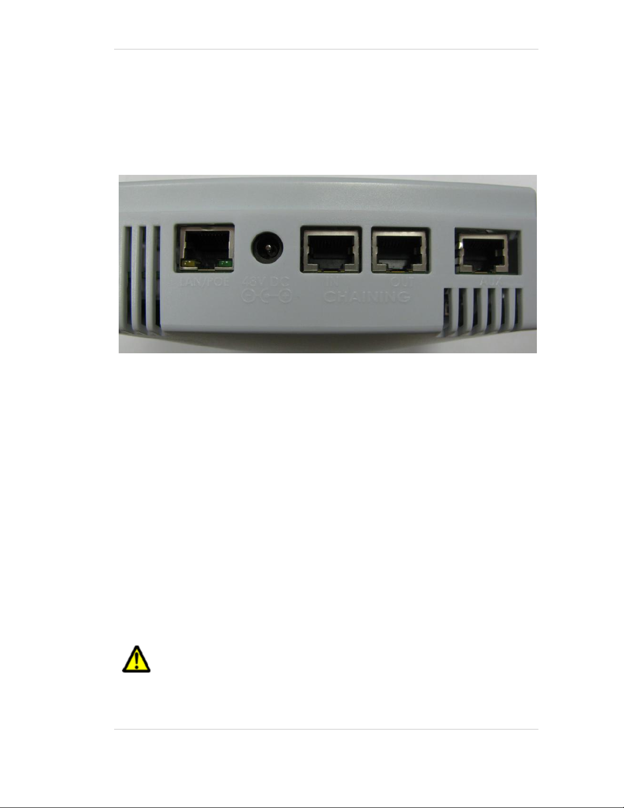
Connectors Panel
Figure 2 describes the Exciter connector panel (bottom panel).
Figure 2: AeroScout EX4200 Exciter Connectors Panel
1. Ethernet LAN Connection – RJ-45 interface. In a configuration that uses a physical
Ethernet cable connection to the LAN, the network cable is attached here. Permanent
connection to a wired network is not mandatory. However you must have a wired
connection for configuring the Exciter. In addition, some of the monitoring functions
will not be available if the Exciter is not wired. This connection is also used for
Power over Ethernet (PoE, 802.3af).
2. Power jack – Accepts an input voltage of 48V DC. This is a standard 2.5mm jack
connector for direct power supply. Alternatively, you can use the power supply that
is packaged along with the Exciter. When PoE is used, this connection is not used.
3. Chain IN Connector – RJ-45 connector. This connector is used for receiving power
from chained Exciters.
4. Chain OUT and Control Connector – RJ-45 connector. This connector is used for
distributing power to chained Exciters and to connect the External LF Antenna unit.
The output voltage is 12V DC.
5. Auxiliary connector – Designed for connecting an External Speaker unit.
EX4200 Features 8
Page 9
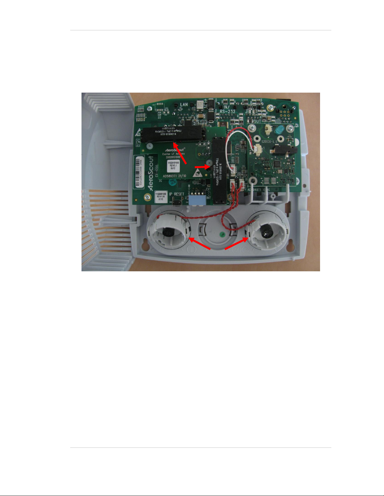
EX4200 Hardware
AeroScout EX4200 Ultrasound Exciter
Figure 3: AeroScout EX4200 Exciter board
The AeroScout EX4200 includes:
1. Two ultrasound speakers - The speakers are rotatable so that they can be
directed towards various points in the room.
2. IP Reset Switch: Restores the device’s IP address to the company default.
3. LF Antennas
EX4200 Hardware 9
Page 10
AeroScout EX4200 Ultrasound Exciter
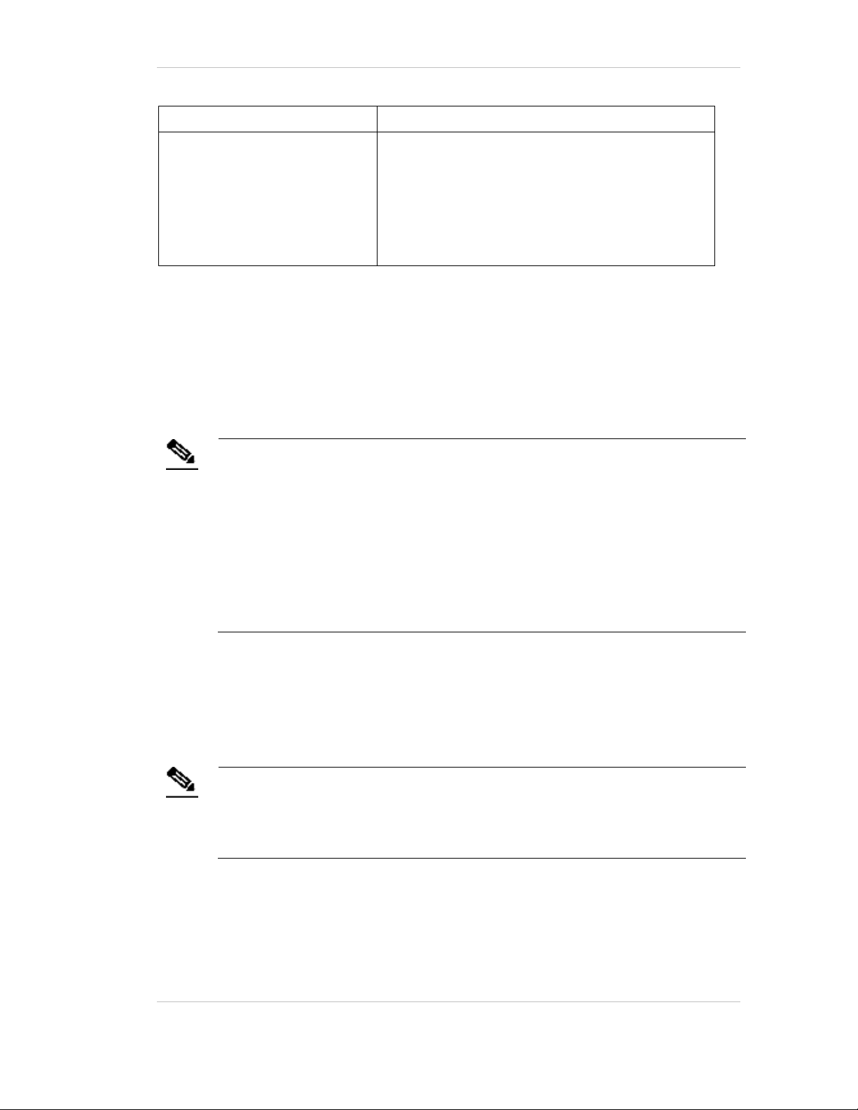
Usage option
Description
Single Exciter – not
connected to network
Exciters can be used as standalone devices that
function independently without any network
connection. In this case you need to connect
the Exciter to the power supply only.
Single Exciter – connected to
network
Exciters can be remotely controlled (for
configuration and monitoring purposes)
through the local area network. In this case
you need to connect it to both a power source
and the network.
AeroScout Exciters also support power-overEthernet (PoE), which supply both power and
network services via a single connection.
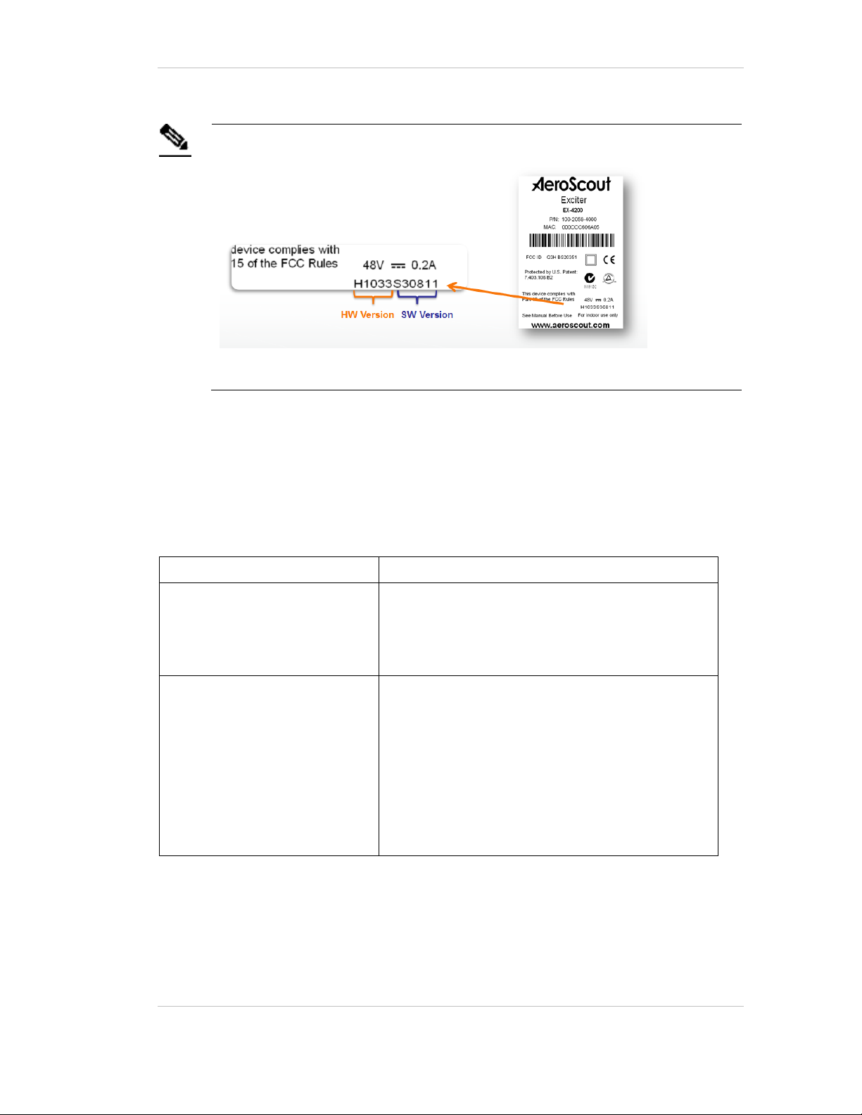
Note
Exciters with Hardware Version H1033 and above are equipped with 2
internal ultrasound speakers.
Figure 4: HW Version indication on Aeroscout Exciters
Connecting the Exciter to the Network and
Power Source
The following is a brief summary of available powering and networking options:
Connecting the Exciter to the Network and Power Source 10
Page 11
AeroScout EX4200 Ultrasound Exciter
Usage option
Description
Single Exciter with External
LF Antenna unit
There is an option to connect an External LF
Antenna unit to the EX4200 Exciter. The
External LF Antenna unit should be mounted
outside the room, next to the door. It should be
configured to turn off the ultrasound receiver
of the T2u Tag.
Note
An Exciter requires approximately 10W of power. When connecting an Exciter
to a direct power source with one of the above voltage levels, verify that the
current level is sufficient.
When using a direct power source for chained Exciters, you can drive power
to no more than three Exciters sequentially even if the source power is
sufficient for more.
Unit shall be powered only by limited power source (marked LPS or NEC
class 2) power supply.
Note
PoE standard 802.3af class 0 allows power for not more than one Exciter.
When using PoE with chained Exciters, a PoE connection must be made to
every single Exciter in the chain. In addition, the LAN connectivity that the
PoE supplies will not be utilized for slave Exciters in a chain.
Power Supply Options
The various power supply options for powering up the Exciter are described below.
Direct Power Supply
Directly connect a 48VDC power source to the Exciter’s power jack (connector 2 in
Figure 2).
PoE Switch
If your network has a Power-over-Ethernet infrastructure, you can connect a CAT-5
Ethernet cable from the PoE switch to the Exciter’s LAN connector (connector 1 in
Figure 2). This supplies both the power and the network connection.
Connecting the Exciter to the Network and Power Source 11
Page 12

AeroScout EX4200 Ultrasound Exciter
Note
An injector can provide enough power for one Exciter only. When using the
injector with chained Exciters, an injector must be connected to every single
Exciter in the chain. In addition, the LAN connectivity that the injector
supplies, is not to be utilized for slave Exciters in a chain.
110/220 VAC to 48VDC PoE Single-Port Injector
The PoE Single Port Injector converts 110/220VAC to 48VDC. In addition, it can
receive a network connection and enable the installer to run a single cable to the
Exciter’s LAN connector, thus supplying both power and network connectivity.
When using this injector, the power jack of the Exciter will not be used.
Figure 5: Single-Port Injector
The injector’s IN connector is connected to the network. The injector’s OUT
connector is connected to the Exciter’s LAN connector (connector 1 in Figure 2).
The injector can be used for both networked and non-networked Exciters. In case of
a non-networked Exciter, the IN connector on the injector is not used.
110VAC/220VAC to 48VDC Power Supply Adaptors
These adaptors convert 110VAC or 220VAC inputs to 48VDC
Connecting the Exciter to the Network and Power Source 12
Page 13

AeroScout EX4200 Ultrasound Exciter
Power supply
Input
Output
Maximum
Current
Available
Power
Maximum #
of Exciters
with one
source
POE single port
injector
100-240V
AC 50-60Hz
48VDC
0.32A
(1)
15.4W
1
Standard POE
802.3af switch
port
(2)
-
48VDC
0.32A
(1)
15.4W
1
External power
source
-
48VDC
>1A
>48W
3
(3)
Note
Cable losses are included assuming cables are less than 100m long.
The POE class should be 0.
The Exciter port cannot support power required by more than three Exciters.
Figure 6: 110VAC to 48VDC or 220VAC to 48VDC Adaptor
The adaptor is connected to the Exciter’s power jack). The network should be
connected separately to the Exciter’s LAN connector (connector 1 in Figure 2). This
adaptor is most common for chained Exciters. It can be used for supplying power to
up to three Exciters.
Power Connection Summary
The following table summarizes the power connection options:
Connecting the Exciter to the Network and Power Source 13
Page 14

AeroScout EX4200 Ultrasound Exciter
Note
The Exciters’ transmission ranges and physical position should be set in a
manner that will allow overlapping between neighboring Exciters’ coverage
areas.
Chaining Exciters
In an area where the required LF coverage exceeds the capacity of one Exciter, you
can chain up to three Exciters, thus extending the coverage area. For example, a large
entrance gate for trucks and heavy equipment that is 30m wide might require three
Exciters chained to one another. This solution is relevant for LF transmissions only.
Exciter EX4200 can be chained to either another Exciter EX4200 or to an Exciter
EX3210.
The chained Exciters are treated by the system as a single entity. Their transmissions
do not interfere with one another.
Figure 6 illustrates chained Exciters and shows the connections.
Figure 7: Exciter chaining
Chain Connection
Up to 3 Exciters can be connected to each other in a chain, as follows:
1. The first Exciter in the chain that’s directly connected to the LAN is called the
“master”. The others are called “slave”. Any EX4200 can be master.
2. The master is connected to the next slave from the master’s OUT connector
(connector 4 3 in Figure 2) to the slave’s IN connector (connector 3 in Figure 2).
Chaining Exciters 14
Page 15

AeroScout EX4200 Ultrasound Exciter
Note
Exciter EX4200 chaining is supported by Exciter FW V308 or higher and Engine
4.3 or higher.
3. A slave is connected to a subsequent slave in the same manner (from OUT to the
next slave’s IN).
4. In the System Manager, under Exciter Properties, Settings, Mark the check box
Exciter is Slave.The slaves will inherit the master's ID and its LF configurations
aside from the transmission range. The transmission range and ultrasound
settings need to be configured individualy for each Exciter.
Figure 8: Slave configuration in System Manager
Chaining Exciters 15
Page 16

AeroScout EX4200 Ultrasound Exciter
Chaining an EX3210 Exciter
To connect the EX3210 Exciter to the EX4200 Exciter, follow these steps:
1. The EX4200 Exciter in the chain that’s directly connected to the PoE/LAN is
called the “master”. The EX3210 Exciter is also a “master”. Each Exciter has its
own ID.
2. Configure the EX3210 Exciter as not connected to the network.
3. Connect the EX3210 Exciter to the Chain Out connector of the EX4210 Exciter.
Chaining Exciters 16
Page 17

AeroScout EX4200 Ultrasound Exciter
Connecting an External LF Unit
The External LF Antenna Unit is designed to cover the exit of a patient room,
typically in the Nurse Call use case. It turns off the Exciter's ultrasound receiver
when the person leaves the room (the Exciter's internal LF antenna turns it on). It is
positioned outside the room covered by the Exciter. The external antenna also clears
the last ultrasound Exciter ID.
The two devices communicate via a standard CAT5 cable connection. Connect the
Exciter's Chaining OUT connector to the external LF unit's IN connector.
The external LF's LED blinks while the Exciter transmits.
Connecting an External Speaker Unit
The external speaker unit is designed to cover smaller rooms such as bathrooms
adjacent to patient rooms or to extend the range of the Exciter in a large room. The
device is equipped with two speakers. You can turn on and off both speakers
independently using the On/Off switches on the side panel.
Figure 9: External LF/Speaker unit
The Exciter and External Speaker unit communicate via a standard CAT5 cable
connection. To connect the External Speaker to the Exciter, first, remove the AUX
connector cover (Figure 10). Second, connect the Exciter's AUX connector to the
External Speaker's IN connector.
Connecting an External LF Unit 17
Page 18

AeroScout EX4200 Ultrasound Exciter
Figure 10: AUX connector cover
Figure 11: External Antenna/ Speaker, IN connector and mounting brackets
Connecting an External Speaker Unit 18
Page 19

AeroScout EX4200 Ultrasound Exciter
Attaching the External LF Antenna and External
Speaker to a false/ acoustic Ceiling
The brackets on the External Units' bottom panel are designed for mounting to a
false ceiling.
Follow these steps:
1. Couple the bottom panel of the external unit with the grid of the false ceiling at
a 45 degree angle.
2. Next, twist the external unit clockwise so that the brackets are aligned with the
grid of the false ceiling.
Figure 12: Mounting an External Unit to a false ceiling
Attaching the External LF Antenna and External Speaker to a false/ acoustic Ceiling 19
Page 20

AeroScout EX4200 Ultrasound Exciter
Figure 13: External Unit mounted on a false ceiling
Attaching an External LF Antenna or an External
Speaker to the Wall
The External LF Antenna and External Speaker can be mounted on a wall using
screws. First screw two screws into the wall at an even height. The distance between
the screws shall be 67.7mm (2 2/3 in) and is also marked on the bottom panel of the
external unit. After the screws are in place on the wall, place the mounting holes
over the screws and hang the external unit.
Attaching an External LF Antenna or an External Speaker to the Wall 20
Page 21

AeroScout EX4200 Ultrasound Exciter
Exciter Configuration
Exciters are configured using the AeroScout System Manager or MSE. The
configuration settings consist of device installation and network definitions.
Configuring the Exciter via System Manager
The configuration procedure involves the following steps:
1. Connect all Exciters with a wired Ethernet connection to a dedicated segment.
2. Add the Exciters with the AeroScout System Manager, configure their
parameters and define their IP settings (The preconfigured IP is supplied per
Exciter).
If you wish to later change the IP settings (IP, subnet, gateway or ports) you can
do so by right-clicking on the Exciter and selecting IP Settings.
3. Check that the Exciter’s status is OK by right clicking on the Exciter icon and
selecting Status. Also verify in the status window that the firmware versions
(DSP and Second Boot) are compatible with the current installed Engine version
and Exciter hardware version. Consult AeroScout Support regarding the
appropriate firmware versions.
4. Position the Exciter in the site according to site survey recommendations, and
mount it.
5. Align the Exciters’ positions according to the required area coverage.
6. If you wish to define the Exciter as an offline Exciter not connected to the
network, you should approve the above configuration, wait for a confirmation,
define the Exciter as disconnected from network from the Properties window,
approve the settings again and disconnect the Exciter from the network.
For more information please refer to the AeroScout Engine User’s Guide.
Configuring the Exciter via MSE
The configuration procedure involves the following steps:
1. Open the WCS and select Configure, Chokepoints.
Exciter Configuration 21
Page 22

Figure 14: Exciter configuration in MSE
2. Select Add Chokepoint.
AeroScout EX4200 Ultrasound Exciter
Figure 15: Adding Chokepoint
3. Enter the Exciter MAC address, name, static IP address, and click the Save
button.
4. Select Monitor, Maps and then the relevant campus, building and floor.
Exciter Configuration 22
Page 23

AeroScout EX4200 Ultrasound Exciter
Figure 16: Exciter configuration in MSE
5. Select Add Chokepoint and click Go.
Figure 17: Exciter configuration in MSE
6. Check the relevant Exciters and click OK.
7. You will be switched back to the relevant floor area.
8. Locate the added Exciter on the map and click Save.
9. Select Services, Synchronize Services and synchronize the relevant MSE.
10. Open System Manager and configure the Exciter.
Exciter Configuration 23
Page 24

AeroScout EX4200 Ultrasound Exciter
Figure 18: System Manager configuration - Settings
11. On the left panel select the Internal LF entry and configure it.
Figure 19: System Manager configuration – Internal LF
12. Repeat the procedure for the External LF Antenna (the parameters are identical
for both).
13. If Ultrasound is enabled, select the US Exciter entry on the left and configure the
ultrasound device.
Exciter Configuration 24
Page 25

AeroScout EX4200 Ultrasound Exciter
Note
Starting from Engine version 4.3, master-slave configuration is done using
System Manager. Use the Slave Exciter Configuration Tool (SECT) for earlier
versions.
Note
Do not connect the console data cable which is used to configure the EX4100
Exciter to the external connector on the EX4200 Exciter housing. This
connector is used only for EX4100 Exciter configuration and EX4200 Exciter
configuration is done only using System Manager.
Figure 20: System Manager configuration –US Exciter
Note the Ultrasound Transmission Power parameter: Usually the power is set
to 5 in patient rooms and to 9 in utility rooms (the power depends on the size of
the room).
For more configuration options and the relevant use cases, please refer to the
AeroScout Exciter Deployment Guide.
Exciter Configuration 25
Page 26

AeroScout EX4200 Ultrasound Exciter
Mounting the Exciter
Mounting the Exciter on a Wall
Mount the Exciter with the AeroScout logo facing up.
Fix the Exciter on the wall using four screws threaded through the four holes at the
back of the casing.
Mounting the Exciter Using a Mounting Plate
The Exciter can be mounted on a wall using the Mounting Plate (provided with the
Exciter), which provides various mounting options, including strapping the mount
on a round surface.
Once the mount is in place, fix the plate on the four hooks and push is down until it
snaps into position.
Figure 21: Exciter Plate
To remove the plate, push the release button on the right, slide the plate up and
remove it from the hooks.
Mounting the Exciter 26
Page 27

AeroScout EX4200 Ultrasound Exciter
Figure 22: Exciter Plate removal
Mounting the Exciter Using a Ceiling Mount
A ceiling mount can also be attached to the Exciter’s fixed mount for mounting on
false or acoustic ceilings.
Figure 23: Ceiling mount
Ceiling Mount
Figure 24: Exciter mounted on the ceiling
Mounting the Exciter 27
Page 28

AeroScout EX4200 Ultrasound Exciter
Medium room size: 7x4.6x2.6m
Exciter is installed on
the wall or ceiling far
from the door
Max leakage 1.5m
Acute angle
Tag
Power=2 (high)
Deployment Considerations
The section provides recommendations on how to deploy the Exciter to prevent
leakage beyond the confines of the room and avoid poor coverage of the room area.
When mounting a single EX4200 Exciter, either mount it on the same wall as the
entrance door or on the ceiling above it. The speaker should be directed away from
the door, towards the opposite wall. The following figure illustrates the case.
Figure 25: Exciter deployment consideration
In larger rooms that cannot be covered by one Exciter, install two Exciters on the
same wall, a few meters apart. Make sure their effective range overlap. The Exciters
should be configured with Enable Multiple Ultrasound Exciters usage in the
room=Yes (check the box). The following figure illustrates the case.
Deployment Considerations 28
Page 29

AeroScout EX4200 Ultrasound Exciter
Big room size: 11x8x2.6m
Exciter is installed on
the wall or ceiling far
from the door
Max leakage 1.5m
Acute angle
Tag
Power=3 (max)
Ultrasound
listen
protocol
WARNING: Devices that transmit an ultrasound signal, like ultrasonic
occupancy detectors, may interfere with the proper functionality of
ultrasound tags. It is recommended to disable the ultrasound components
of these devices.
Figure 26: Multiple Exciter deployment consideration
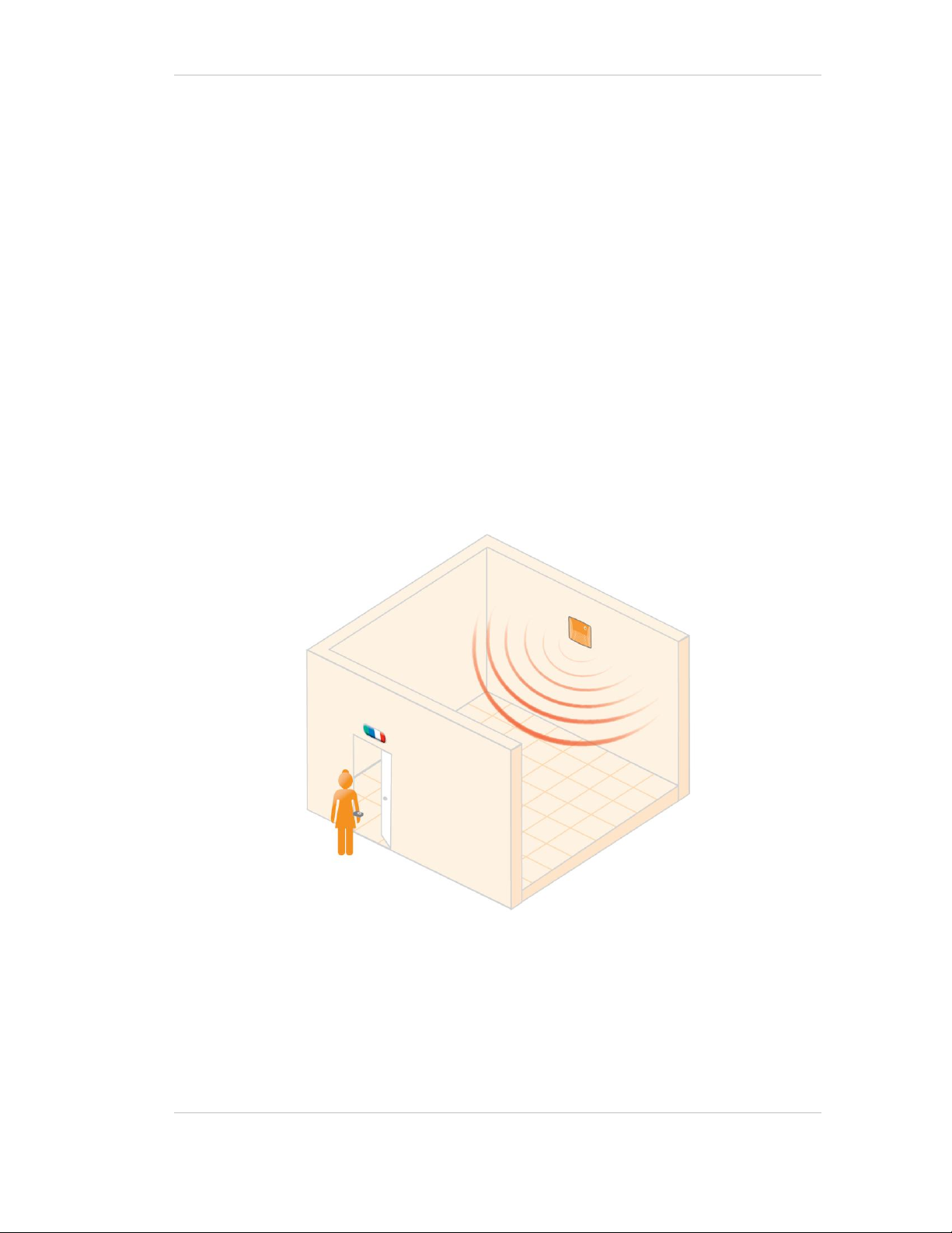
In a Nurse Call application, the EX4200 Ultrasound Exciter can be deployed with a
chained LF Exciter.
The EX4200 Exciter is mounted at the entrance of the room (inside). When the tag
enters the room, the on-board LF enables the ultrasound receiver. An External LF
Antenna unit or EX3210 Exciter is mounted outside the room, at the entrance. The LF
should cover the entrance with minimal leakage into the room or into adjacent
rooms. The External LF Antenna unit disables the ultrasound receiver when the tag
leaves the room.
For more information on deployment considerations, please refer to the Exciter
Deployment Guide.
29
Page 30

AeroScout EX4200 Ultrasound Exciter
Product
SKU
Description
EX4200
Exciter
EX-4200
EX4200 Ultrasound Exciter. Includes 48V DC input,
Ethernet and PoE interface
EX4200
Power Supply
ADP-047
AC/DC adaptor 45W 48V/1.0A 90-264VAC.
Exciter
Detector Tool
EXD-1000
Tool for visualization of the effective Ultrasound and LF
Exciter transmission field. Analyzes the Exciter coverage
during deployment. Includes a PC application and the
detector hardware that can be connected via USB to a
PC.
Ceiling
Mounting
Adapter
LRAC-100
For false/acoustic ceilings
External LF
Antenna
ANT-4200
External LF Antenna Unit for EX4200 and EX2000B
Exciters. Powered directly from the connection to the
EX4200 or EX2000B Exciter. Includes mounting plate
and a ceiling mount.
External
Speaker unit
SPK-4200
External ultrasound speaker unit for EX4200 Exciter.
Powered directly from the connection to the EX4200
Exciter. Includes mounting plate and a ceiling mount
Ultrasound Exciter Hardware Components
Use the following information to determine the correct part number of the Exciter
depending on the required hardware:
Ultrasound Exciter Hardware Components 30
Page 31

AeroScout EX4200 Ultrasound Exciter
Specifications
EX4200 Exciter
Physical and Mechanical
Dimensions: 162mm x 142mm x 55mm (63.8in x 55.9in x 21.6in) – without
the mounting plate
Weight: 300g (11oz)
Housing: ABS, indoor use only
Coverage
Adjustable coverage range up to 8m x 8m (26ft x 26ft)
Ultrasound Transmitter
Frequency 40-60 KHz
LF Channel
125kHz
Field intensity limits: 37.3dBµA/m at 10m (ETSI)
Propagation limits: 21.8dBµV/m at 300m (FCC)
Modulation: ASK
Network Interface
Ethernet (RJ-45)
Power
Input voltage: 48VDC
PoE (802.3af) – 48VDC
Maximum power consumption: 6W.
Maximum power consumption of External LF Unit: 6W.
Environmental
Operating temperature: 0°C to +50°C (32°F to 122°F)
Humidity: 0 to 95%, non-condensing
Specifications 31
Page 32

AeroScout EX4200 Ultrasound Exciter
Certifications
Safety:
FCC Part 15, sub-part C class B, sub-part B
EN 300-328, EN 300-330, EN 301-489
CE and cTUVus (EN60950)
External LF Antenna
Physical and Mechanical
Dimensions: 93mm x 84mm x 34 mm (3.7in x 3.3in x 1.3in)
Weight: 100 gr (3.5 oz)
Housing: ABS, indoor use only
RJ-45 Input Connector
Connected to the Exciter’s Chain Out connector
Coverage
Adjustable coverage range: 0.25m-3m (0.8ft x 9.8ft)
Power
Powered directly from the Exciter
Environmental
Operating temperature: 0°C to +50°C (32°F to 122°F)
Storage temperature: -40°C to +85°C (104°F to 185°F)
Other:
Connecting to EX2000B Exciter requires a 48/12V adapter
External Speaker
Physical and Mechanical
Dimensions: 93mm x 84mm x 34 mm (3.7in x 3.3in x 1.3in)
Weight: 80 gr (2.8oz)
Housing: ABS, indoor use only
Specifications 32
Page 33

AeroScout EX4200 Ultrasound Exciter
RJ-45 Input Connector
Connected to the Exciter’s AUX connector
2 Speakers
Coverage
Adjustable coverage range up to 5m x 5m 16.4ft x 16.4ft)
Power
Powered directly from the Exciter
Environmental
Operating temperature: 0°C to +50°C (32°F to 122°F)
Specifications 33
Page 34

AeroScout EX4200 Ultrasound Exciter
WARNING: This device complies with Part 15 of the FCC Rules and RSS-210 of Industry and
Science Canada. Operation is subject to the following two conditions: (1) This device may not cause
harmful interference, and (2) this device must accept any interference received, including
interference that may cause undesired operation.
This device complies with Industry Canada license-exempt RSS standard(s). Operation is subject to
the following two conditions: (1) this device may not cause interference, and (2) this device must
accept any interference, including interference that may cause undesired operation of the device.
Le présent appareil est conforme aux CNR d'Industrie Canada applicables aux appareils radio
exempts de licence. L'exploitation est autorisée aux deux conditions suivantes : (1) l'appareil ne
doit pas produire de brouillage, et (2) l'utilisateur de l'appareil doit accepter tout brouillage
radioélectrique subi, même si le brouillage est susceptible d'en compromettre le fonctionnement.
Safety and Warnings
FCC STATEMENT
This equipment has been tested and found to comply with the limits for a Class B digital device,
pursuant to Part 15 of the FCC rules. These limits are designed to provide reasonable protection
against harmful interference in a residential installation. This equipment generates, uses and can
radiate radio frequency energy and, if not installed and used in accordance with the instructions, may
cause harmful interference to radio communications. However, there is no guarantee that
interference will not occur in a particular installation. If this equipment does cause harmful
interference to radio or television reception, which can be determined by turning the equipment off
and on, the user is encouraged to try to correct the interference by one or more of the following
measures:
a) Reorient or relocate the receiving antenna.
b) Increase the separation between the equipment and receiver.
c) Connect the equipment to an outlet on a circuit different from that to which the receiver is
connected.
d) Consult the dealer or an experienced radio/TV technician.
This device complies with Part 15 of the FCC Rules.
Operation is subject to the following two conditions:
a) This device may not cause harmful interference
b) This device must accept any interference received, including interference that may cause undesired
operation.
FCC Warning
Modifications not expressly approved by the manufacturer could void the user authority to operate
the equipment under FCC Rules.
Safety and Warnings 34
Page 35

AeroScout EX4200 Ultrasound Exciter
Limited Warranty
Hardware. AeroScout Inc. ("AeroScout") warrants that commencing from the date of delivery to Customer and
continuing for a period of one (1) year thereafter (the “Warranty Period”), the Hardware will be free from defects in
material and workmanship under normal use subject to terms hereof. The date of shipment of a Product by
AeroScout is set forth on the packaging material in which the Product is shipped. This limited warranty extends only
to the original user of the Product. Customer's sole and exclusive remedy and the entire liability of AeroScout and its
suppliers under this limited warranty will be, at AeroScout’s or its service center's option, shipment of a replacement
within the period or a refund of the purchase price if the Hardware is returned to the party supplying it to Customer, if
different than AeroScout, freight and insurance prepaid. AeroScout replacement parts used in Hardware repair may
be new or equivalent to new. AeroScout’s obligations hereunder are conditioned upon the return of affected articles
in accordance with AeroScout’s then-current Return Material Authorization (RMA) procedures.
Restrictions: This warranty does not apply if the Product (a) has been altered, except by AeroScout, (b) has not
been installed, operated, repaired, or maintained in accordance with instructions supplied by AeroScout, (c) has
been subjected to abnormal physical or electrical stress, misuse, negligence, or accident; or (d) is provided for beta,
evaluation, testing, or demonstration purposes for which AeroScout does not receive a payment of purchase price or
license fee.
Exclusions:
This warranty shall have no coverage of the following:
Batteries (other than DOA -Dead On Arrival)
Plastics (including defects in appearance, cosmetics, decorative or structural items including framing and
non-operative parts).
Tag Calibration
Expenses related to removing or reinstalling the Product
Defects or damage that result from the use of Non-AeroScout certified Products, Accessories, Software or other
peripheral equipment are excluded from coverage.
Defects or damages resulting from service, testing, adjustment, installation, maintenance, alteration, or modification
in any way by someone other than AeroScout, or its partners, are excluded from coverage.
Extended Warranty:
AeroScout offers an extended warranty. The initial year of the extended warranty must be purchased at the time of
the product purchase or before the original warranty expires. The extended warranty may be renewed again for a
maximum of two additional years (on top of the initial warranty period). Warranty extensions must be purchased
prior to the existing warranty expiration and will not be available after the original/extended warranty expires.
DISCLAIMER OF WARRANTY. EXCEPT AS SPECIFIED IN THIS WARRANTY, ALL EXPRESS OR IMPLIED
CONDITIONS, REPRESENTATIONS, AND WARRANTIES INCLUDING, WITHOUT LIMITATION, ANY IMPLIED
WARRANTY OR CONDITION OF MERCHANTABILITY, FITNESS FOR A PARTICULAR PURPOSE,
NONINFRINGEMENT, SATISFACTORY QUALITY OR ARISING FROM A COURSE OF DEALING, LAW, USAGE,
OR TRADE PRACTICE, ARE HEREBY EXCLUDED TO THE EXTENT ALLOWED BY APPLICABLE LAW. TO THE
EXTENT AN IMPLIED WARRANTY CANNOT BE EXCLUDED, SUCH WARRANTY IS LIMITED IN DURATION TO
THE WARRANTY PERIOD. BECAUSE SOME STATES OR JURISDICTIONS DO NOT ALLOW LIMITATIONS ON
HOW LONG AN IMPLIED WARRANTY LASTS, THE ABOVE LIMITATION MAY NOT APPLY TO YOU. THIS
WARRANTY GIVES YOU SPECIFIC LEGAL RIGHTS, AND YOU MAY ALSO HAVE OTHER RIGHTS, WHICH
VARY FROM JURISDICTION TO JURISDICTION.
This disclaimer and exclusion shall apply even if the express warranty set forth above fails of its essential purpose.
Under no circumstances shall AeroScout’s liability under this limited warranty exceed the actual cash value of the
Product at the time Consumer returns the Product for repair, determined by the price paid by Consumer for the
Product less a reasonable amount for usage.
Please use the following link to submit your tickets using AeroScout’s support portal:
http://support.aeroscout.com
Limited Warranty 35
Page 36

About AeroScout
AeroScout is the market leader in Unified Asset Visibility solutions. Clients improve operational
efficiency and quality using AeroScout products that leverage standard Wi-Fi networks to track and
manage the location, condition and status of mobile assets and people. AeroScout’s global customer
base consists of leading hospital, manufacturing and logistics organizations, including many of the
Fortune 500. The company originally invented the first Wi-Fi-based Active RFID tag, and today is
widely recognized as leading the market in number of deployments and tags shipped. Headquartered
in Redwood City, Calif., AeroScout has offices in Europe, Asia, the Middle East, Latin America and
Australia. For more information, please visit www.aeroscout.com.
AeroScout (Headquarters)
1300 Island Drive
Suite 202
Redwood City, CA 94054
Tel: +1 (650) 596-2994
Fax: +1 (650) 596-2969
E-mail: info@aeroscout.com
Europe, Middle East, Africa Office
Tel : +32 2 709 29 49
Fax : +32 15 30 80 99
E-mail: emea@aeroscout.com
Japan Office
Tel: +81 3 3556 9003
Fax: + 81 3 5875 3723
E-mail: info@aeroscout.co.jp
Latin America Office
Tel : +52 55 5001 5769
E-mail: latam@aeroscout.com
Asia-Pacific Sales
Tel : +1 650 596 2994
E-mail: apac@aeroscout.com
Australia and New Zealand Sales
Tel : +61 3 9038 8690
E-mail: anz@aeroscout.com
 Loading...