

Aeroqual AQ-500 Set EF, AQ-300 Set EF, AQ-300 Set OZL, AQ-300 Set EOZ, AQ-500 Users guide
...Page 1
Aeroqual Limited
460 Rosebank Road, Avondale
Auckland, New Zealand
t +64 9 623 3013
f +64 9 623 3012
aeroqual.com
Page 2

Table of Contents
1 Monitor Components .................................................................................................................... 4
2 Quick Start Guide .......................................................................................................................... 5
2.1 Connecting the Battery ............................................................................................................ 5
2.2 Charging the Battery ............................................................................................................... 6
2.3 Connecting the Sensor Head .................................................................................................. 6
3 Sensor Heads ................................................................................................................................ 7
3.1 Sensor Head Technology ........................................................................................................ 7
3.2 Sensor Head Variants ............................................................................................................. 8
3.3 Sensor Head Warm-Up ........................................................................................................... 9
3.4 Sensor Head Failure Modes ................................................................................................... 9
4 Monitor Operation ....................................................................................................................... 10
4.1 Powering On/Off and Standby .............................................................................................. 10
4.2 Menu Functions ..................................................................................................................... 11
5 Aeroqual Monitor Software (Series 500) ................................................................................... 17
5.1 Computer Requirements ....................................................................................................... 17
5.2 Connect to Monitor ................................................................................................................ 17
5.3 Monitor Setup ........................................................................................................................ 17
5.4 Data Logging ......................................................................................................................... 18
6 External Control Wiring (Series 300 & 500) .............................................................................. 22
6.1 Wiring for Alarm..................................................................................................................... 22
6.2 Wiring for Control .................................................................................................................. 23
6.3 Wiring the 0-5 V Analogue Output ........................................................................................ 23
7 Calibration .................................................................................................................................... 24
7.1 Calibration FAQ's .................................................................................................................. 24
7.2 Calibration Certificate ............................................................................................................ 26
7.3 Calibration Accessory ........................................................................................................... 26
7.4 Bump Test ............................................................................................................................. 27
7.5 Zero Calibration ..................................................................................................................... 27
7.6 Span Calibration (Series 300 and 500) ................................................................................. 28
7.7 Health and safety during calibration ...................................................................................... 29
8 Specifications .............................................................................................................................. 32
8.1 Dimensions ............................................................................................................................ 33
9 Optional Accessories: ................................................................................................................ 34
9.1 Temperature and Relative Humidity Sensor (HH TRH) ........................................................ 34
9.2 Handheld Enclosure (HH ENC)............................................................................................. 34
9.3 Remote Sensor Head Adaptors (AS R10 / AS R13) ............................................................. 36
10 Troubleshooting .......................................................................................................................... 37
MRK-D-0022 V4 Aeroqual Series 200, 300 & 500 User Guide Page | 2
Page 3

10.1 Sensor Failure ....................................................................................................................... 39
11 Technical Support ....................................................................................................................... 39
12 Care and Maintenance ................................................................................................................ 40
12.1 Disposal / Recycling .............................................................................................................. 40
13 Appendix ...................................................................................................................................... 41
13.1 General Guidelines on the Measurement of Gases .............................................................. 41
13.2 Specific Guidelines on the Measurement of Ozone .............................................................. 42
13.3 Sensor Characteristics .......................................................................................................... 43
13.4 Gas Sensitive Electrochemical (GSE) Sensor - Ozone ........................................................ 44
13.5 Gas Sensitive Electrochemical (GSE) Sensor - Other .......................................................... 45
13.6 Particulate Matter Sensor Head PM10 / PM2.5 sensor ........................................................ 47
13.7 Volatile Organic Compound (VOC) sensors ......................................................................... 49
14 Copyright ..................................................................................................................................... 55
15 Software License ......................................................................................................................... 55
16 Terms and Conditions ................................................................................................................ 55
17 Statements of Compliance ......................................................................................................... 56
MRK-D-0022 V4 Aeroqual Series 200, 300 & 500 User Guide Page | 3
Page 4
Component
Series 200
Series 300
Series 500
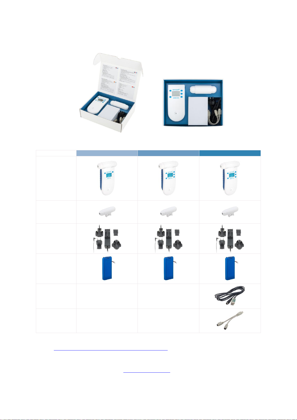
Monitor base
Sensor head
(If ordered)
12 VDC AC/DC
Lithium Smart
Charger
Battery pack –
11.1V Lithium
Polymer
USB to monitor
cable
Two-way PS2
adapter cable
1 Monitor Components
The following components are supplied with each monitor:
NOTE: Data logging software for the Series 500 can be found at:
https://www.aeroqual.com/support/product-software
Please check that all these components have been supplied, if any of the components are missing,
contact your distributor, or Aeroqual at: [email protected].
Replacement batteries, sensor heads and other accessories can be purchased separately.
MRK-D-0022 V4 Aeroqual Series 200, 300 & 500 User Guide Page | 4
Page 5
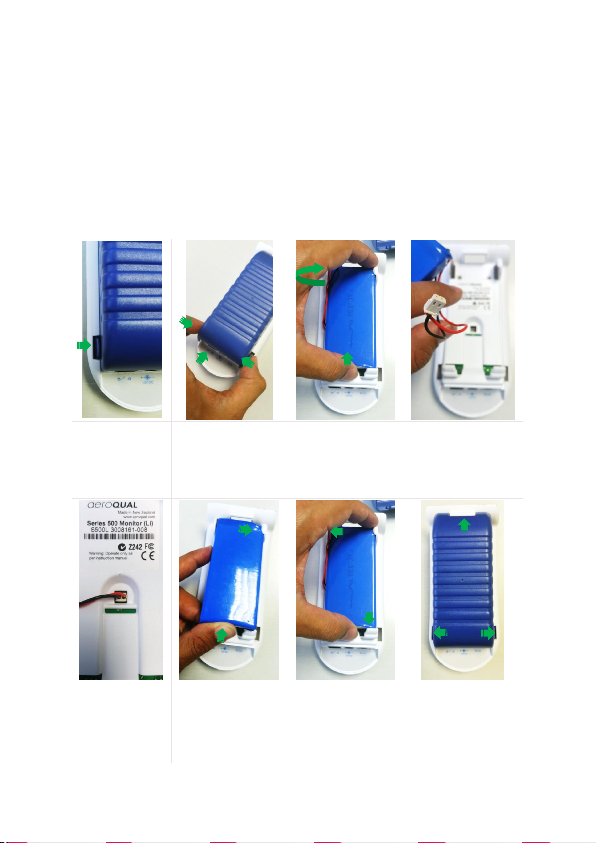
Push tabs on both
sides in.
Holding in both tabs
pull the blue battery
cover upwards. If it is
difficult to move then
you may be squeezing
too tight.
With the cover
removed the battery is
visible. Push the base
of the battery forward
to clear the clips at the
bottom.
The battery is shipped
unplugged.
Insert the connector
and firmly depress.
Gently tug on the
wires to ensure the
plug does not come
free.
Reinsert the battery by
locating the top right
hand corner under the
top right tab.
Push down the top left
side of the battery,
position the battery into
place under the clips at
the bottom.
Re-engage the top
hinge of the cover,
swing down and shut,
ensuring tabs lock cover
into place.
2 Quick Start Guide
The following actions need to be completed before the monitor is ready for use:
1. Connect the battery.
2. Charge the battery.
3. Connect the sensor head.
2.1 Connecting the Battery
The battery is shipped installed in the monitor but disconnected. Follow the steps below to connect
the battery.
MRK-D-0022 V4 Aeroqual Series 200, 300 & 500 User Guide Page | 5
Page 6

2.2 Charging the Battery
IMPORTANT
Switch off the monitor before removing the sensor head
Do not use the battery pack for any other purpose than operating the Aeroqual monitor
Do not disassemble or deface the batteries as this may cause burns
Do not incinerate or heat as this may cause burns, the batteries may burst or cause the release of
toxic materials
Do not short circuit as this may cause burns
Use only batteries approved by Aeroqual and recharge your battery only with the AC/DC adaptor
supplied with the instrument
Never use any charger or battery that is damaged or worn out
Batteries must be recycled or disposed of properly. They must not be disposed of in municipal
waste
Never charge the battery in a hermetically sealed container
Perform charging at temperatures between 0 °C to 45 °C
With the adaptor plugged in and monitor off allow 3 hours for the battery to fully charge.
A new battery's full performance is achieved only after a number of complete charge and discharge
cycles. A fully charged battery will run for approximately 8 hours depending on the sensor head
being used.
Smart Charger LED Status
Red LED = Battery is charging OR battery is fully charged and monitor is on.
Green LED = Battery is fully charged and monitor is off.
NOTE: The unit can be charged when switched on but it will charge more slowly. The battery
can be charged with the sensor head installed or removed from the base.
2.3 Connecting the Sensor Head
IMPORTANT
Do not insert/remove the sensor head while the monitor is switched on. This may damage the
unit. If the sensor head is removed under these conditions without AC/DC adapter connected,
the unit will automatically shut down.
Always place the sensor head perpendicular to the air flow to avoid damage to the sensor.
Sensors require a warm-up period before operation, refer to Section 3.3.
To avoid damage to the sensor, do not shake or invert the monitor when a sensor is attached.
Sensor heads have a keyed connector and are shaped to ensure correct insertion into the monitor
base. When the sensor is fully inserted you can turn on the monitor. Sensors require a warm-up
period before operation, refer to Section 3.3.
MRK-D-0022 V4 Aeroqual Series 200, 300 & 500 User Guide Page | 6
Page 7
Type
Description
Design
GSS
Our gas sensitive semiconductor (GSS) sensor uses proprietary
sensing material, built in automatic baseline correction (ABC) and
interference rejection. This combination results in ppb resolution and a
highly linear response.
GSE
Our gas sensitive electrochemical (GSE) sensors generate nano-amp
currents proportional to the gas concentration. Aeroqual uses low noise
electronics to capture these signals resulting in low detection levels.
LPC
Our laser particle counter (LPC) for Particulate Matter (PM)
measurements uses optimized signal processing using low noise
electronics, we add algorithms to correct for interferences, e.g.
humidity.
NDIR
Our non-dispersive infrared (NDIR) sensor uses infra-red light, a
narrow band-pass filter and photodiode to measure the intensity of light
at the gas absorption band. The light intensity is proportional to the gas
concentration.
PID
Our photoionization detector (PID) sensor uses a krypton filled UV
lamp to ionize VOC gas molecules and generate a current that is
proportional to the VOC concentration. The PID sensor responds to a
wide range of VOCs and is industry recognized.
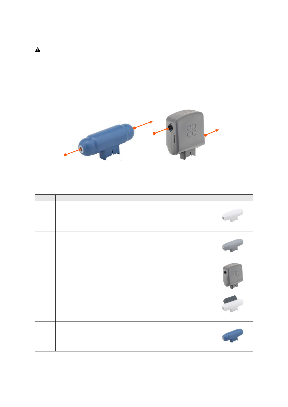
Outlet
(On side)
Inlet
(Mesh screen)
Inlet
Outlet
(On end)
3 Sensor Heads
IMPORTANT
Do not insert/remove the sensor head while the monitor is switched on. This may damage the
unit. If the sensor head is removed under these conditions without AC/DC adapter connected,
the unit will automatically shut down.
Always place the sensor head perpendicular to the air flow to avoid damage to the sensor.
Sensors require a warm-up period before operation, refer to Section 3.3.
3.1 Sensor Head Technology
Aeroqual sensors are as unique as the monitors and accessories they are compatible with. Below are
the different sensor technologies and the designs you may encounter.
All sensors in the portable range benefit from active sampling and come factory calibrated.
NOTE: Sensor head colours vary by gas type, not all colours are shown in the table above.
MRK-D-0022 V4 Aeroqual Series 200, 300 & 500 User Guide Page | 7
Page 8
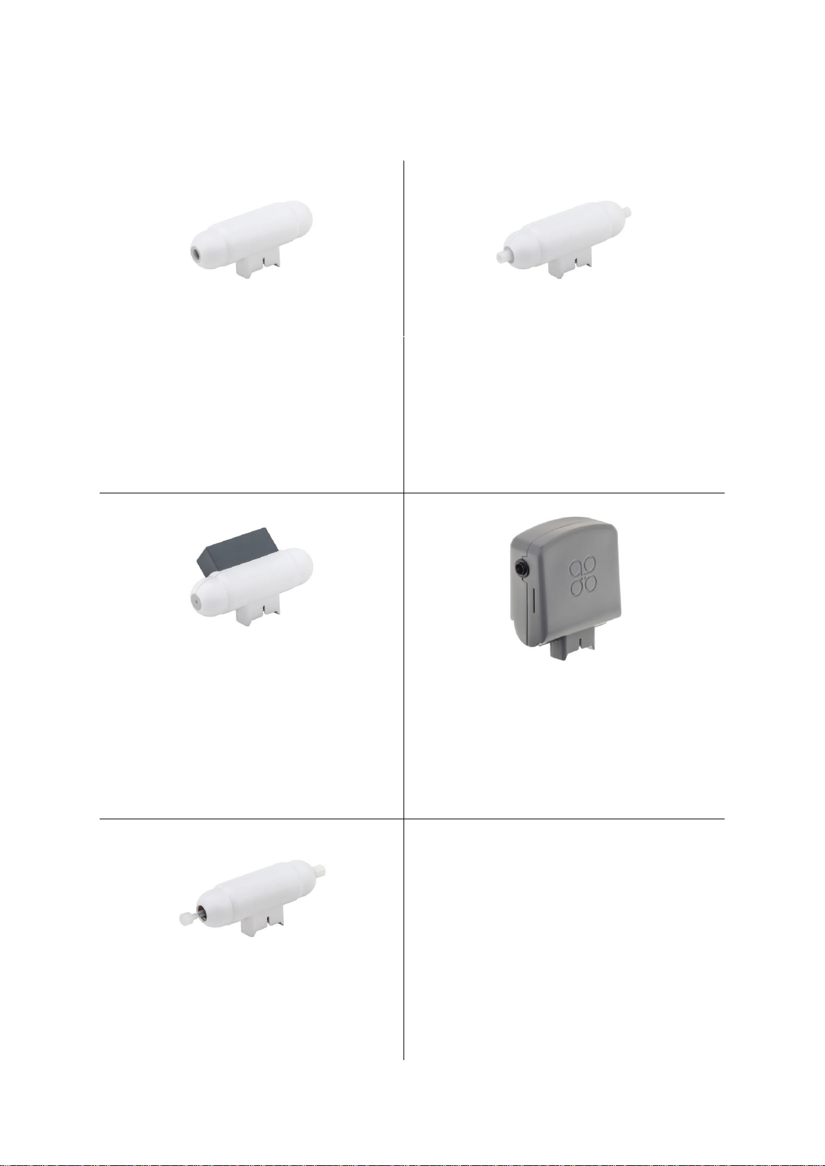
Sensor Head Type 1
Compatible with: Series 200 / 300 / 500
Standard Remote Sensor Kit and Series 900
fixed monitors
Not compatible with: Industrial Enclosure,
and IP 41 Remote Senor Kit
Sensor Head Type 2
Required for: Industrial Enclosure, and IP41
Remote Sensor Kit and Series 930 fixed monitors
Sensor Head – Carbon Dioxide
Compatible with: Series 200 / 300 / 500
Standard Remote Sensor Kit
Not compatible with: Industrial Enclosure,
and IP 41 Remote Senor Kit
Sensor Head – Particulate Matter
Compatible with: Series 200 / 300 / 500
Standard Remote Sensor Kit
Not compatible with: Industrial Enclosure, and
IP 41 Remote Senor Kit
Sensor Head Type 4
Required for: Series 940 fixed monitors only
3.2 Sensor Head Variants
Sensor heads come in a variety of shapes and configurations to suit different gases and accessories.
MRK-D-0022 V4 Aeroqual Series 200, 300 & 500 User Guide Page | 8
Page 9

3.3 Sensor Head Warm-Up
When the monitor is switched on the sensor needs to warm up to burn off any contaminants, there are
two stages:
3 minutes; sensor WARMING UP, no measurement
7 minutes; sensor stabilising, measurement is flashing
When not being used, keeping the monitor in ‘standby’ mode will keep the sensor heated and prevent
a build-up of contaminants.
If the sensor is new (or unused for long periods) it can take up to 24 hours for the message
WARMING UP (or SENSOR FAILURE in older models) to disappear. Should the message remain
after this time, a genuine sensor failure may have occurred, see Section 10.
For an ozone sensor, 24 hours is a conservative time to burn off contaminants and achieve its stated
performance specification. In most instances this will be achieved well within 24 hours. The warm-up
period can be reduced by subjecting the sensor to elevated ozone levels for a short period. For
example, 0.1 ppm of ozone for 5 minutes typically reduces the warm-up time to < 30 minutes.
3.4 Sensor Head Failure Modes
There are two possible sensor failure modes that will be indicated on the display:
SENSOR FAILURE, REPLACE SENSOR
The sensor head should be replaced as there has been a component failure.
SENSOR AGING (Ozone Low/Ultra Low sensor heads only)
The sensor has reached the end of its usable life, the measurement readings can no longer
be relied upon to be within specification.
See also Trouble shooting in Section 10.
MRK-D-0022 V4 Aeroqual Series 200, 300 & 500 User Guide Page | 9
Page 10
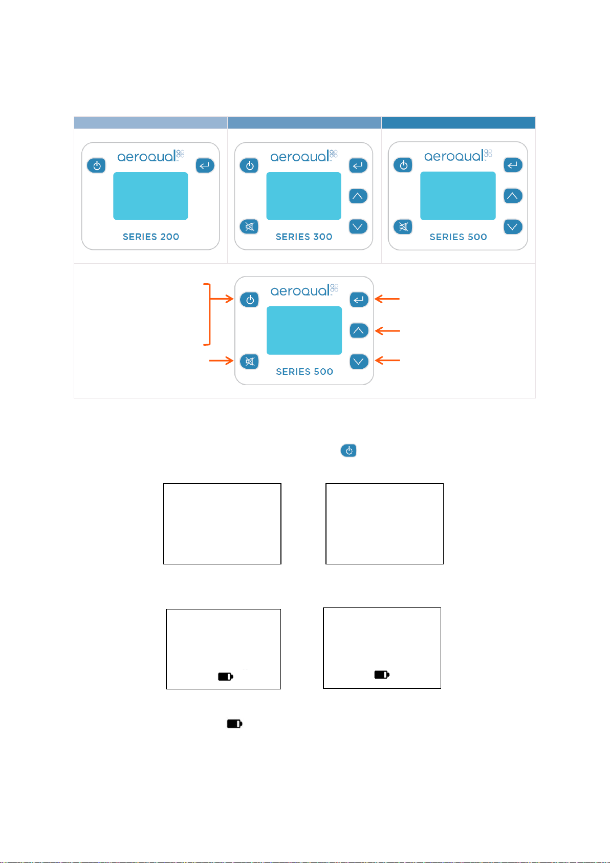
Alarm mute
Scroll down
Scroll up
Series 200
Series 300
Series 500
AEROQUAL
MONITOR
S500 V6.4
LITHIUM BATTERY
O3 ULOW
WARMING UP
3 MINUTES
SV 7.1
M 01
L 01
O3 ULOW
ppm
M 02
O3 UL 0.080
ppm
M 02
Enter
Power button
Series 300 / 500
Power / Scroll button
Series 200
4 Monitor Operation
The following instructions detail the operation and set up of the monitor:
4.1 Powering On/Off and Standby
To turn the monitor on: Press and hold the power button until the screen activates. The monitor
will turn on and the display will appear as below:
After 5 seconds the display will change to indicate the type of sensor head and the monitor will enter
WARMING UP mode (see Section 3.3), after which the main display will appear as below:
TEMP 21.6C
0. 080
or
RH 35.1%
Gas only Gas / Temp / RH
The battery indicator does not represent the remaining battery life.
M and L (Monitor ID and Location ID) only show on the Series 300 and 500.
Only 3 parameters can be shown on the screen at one time. If a sensor captures more
than one parameter (e.g. PM
MRK-D-0022 V4 Aeroqual Series 200, 300 & 500 User Guide Page | 10
/PM10 sensor head) they will scroll up the screen.
2.5
Page 11
EXIT
MONITOR ID
UNITS
OUTPUT SENSOR
ALARM POINTS
CONTROL POINTS
MUTE KEY
CLOCK SETUP
EXIT
LOCATION ID
MAX MIN AV
CALIBRATE
MONITOR SET UP
EXIT
LOCATION ID
MAX MIN AV
CALIBRATE
MONITOR SETUP
LOGGING SETUP
EXIT
ZERO CAL
UNITS
MIN MAX AV
MUTE KEY
LOG FREQ
CLEAR LOG
LOGGING
Series 500 only
To turn the monitor off: Press and hold the power button for 2 seconds until the monitor
beeps. The display will now be blank and operation of the monitor will cease.
To activate standby mode: With the monitor on, press the power button once. This will stop
operation of the monitor; however the sensor will be kept warm.
This mode is used to conserve power between operations but keep the sensor ready to measure the
gas concentration with only a short warm-up phase needed. In this mode the display will show the
sensor type and standby symbol .
To return the monitor to operational mode press the power button .
NOTE: When using a Carbon Dioxide sensor head in standby mode, the sensor runs at full power
and the fan remains on.
4.2 Menu Functions
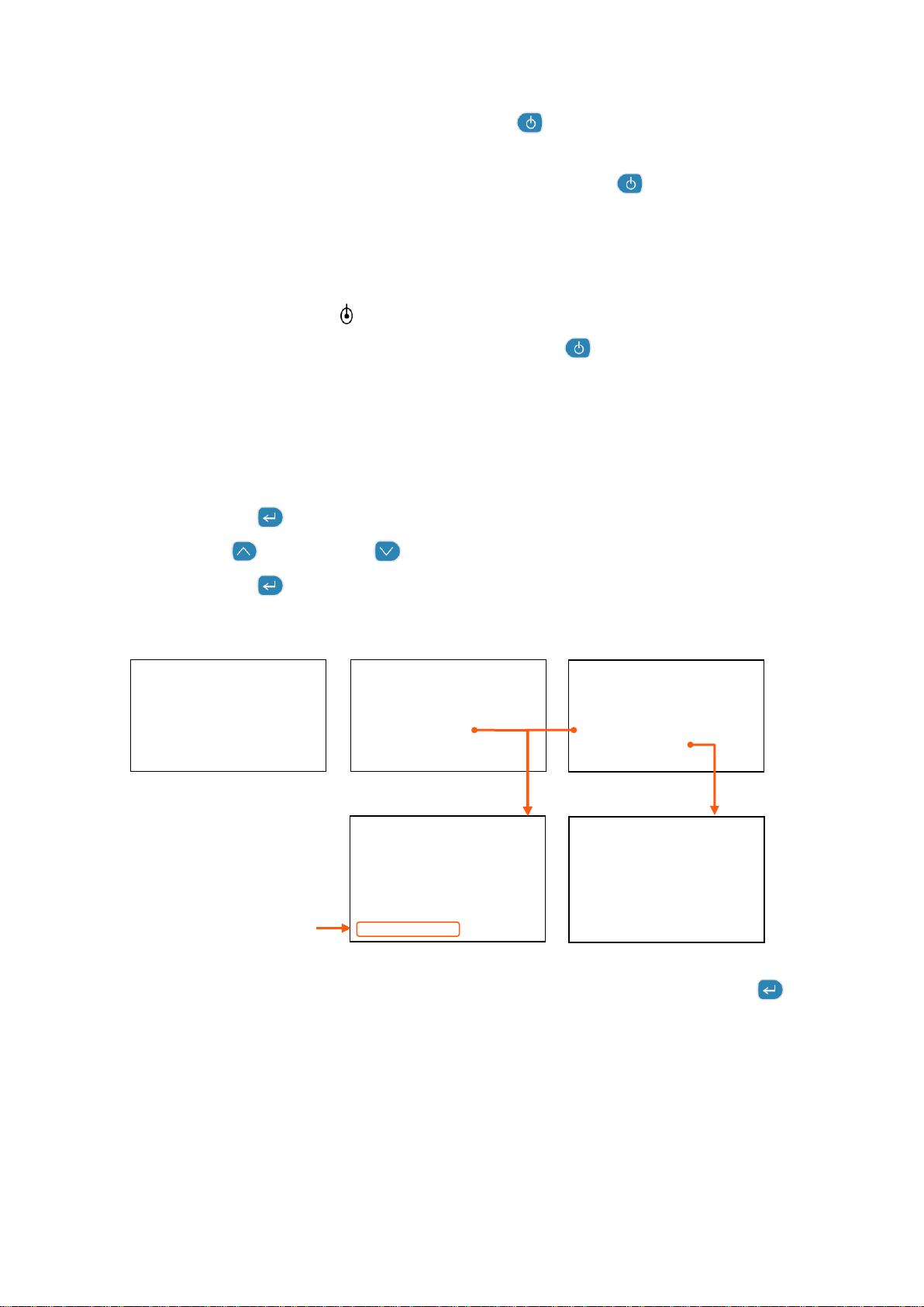
Use the enter button to enter the SETUP menu.
Use the scroll up and scroll down buttons to navigate, select options, and change values.
Use the enter button to confirm the selections and changes.
Series 200 Series 300 Series 500
To exit a menu; complete the action for the menu you are in, or scroll to EXIT and press enter .
Each menu item is covered in the following sub-sections.
MRK-D-0022 V4 Aeroqual Series 200, 300 & 500 User Guide Page | 11
Page 12

O3 UL
PPM
RD 0.010
MIN 0.005
MAX 0.024
AVE 0.015
O3 UL TEMP RH
PPM C %
RD 0.010 23 50
MIN 0.005 22 50
MAX 0.024 25 56
AVE 0.015 24 54
4.2.1 ZERO CAL
See section 7.4
4.2.2 UNITS
In the Series 300 and 500, UNITS is found under MONITOR SETUP. Use the scroll up and scroll
down buttons to select the required units, press enter to confirm the selection.
ppm or mg/m3 for gases
mg/m3 for particulate matter (PM) only
If a temperature and humidity sensor is attached, choose from:
°C or °F
4.2.3 MAX MIN AV
When activated, MIN MAX AV displays the minimum, maximum and average readings from the start
of the measurement cycle.
To activate:
Select MAX MIN AV
Select START to initiate the measurement cycle and return to the setup menu
Scroll to EXIT to return to the main display
The readings will scroll up the screen
NOTE: Only three parameters will be shown on the screen at one time.
In the Series 300 and 500, the MAX MIN AV cycle can also be initiated from the main display by
holding down the scroll down button for 2 seconds until the unit beeps. Hold down the scroll
down button again for 2 seconds to stop the measurement cycle.
When the MAX MIN AV cycle is initiated, the display should read as seen below:
or
NOTE: The RD value is the current reading. The speed of the display scrolling is dictated by the
MRK-D-0022 V4 Aeroqual Series 200, 300 & 500 User Guide Page | 12
slowest sensor. The display will scroll every time a new set of readings have been taken.
Page 13

4.2.4 ZERO CAL / CALIBRATE
Select ZERO CAL on the Series 200, or CALIBRATE on the Series 300 and 500.Then to enter the
CALIBRATE menu, hold down the mute button and scroll down button for 2 seconds. ZERO
CAL or SPAN CAL can be selected.
For information on how to calibrate the sensor heads please refer to Section 7.
4.2.5 MUTE
Mute silences the audible feedback ‘beeps’ that occur when you press a button.
Select MUTE KEY (Series 200) or under MONITOR SETUP (Series 300 and 500).
Press the enter to silence the audible feedback ‘beeps’, the word MUTED will appear
next to MUTE KEY.
NOTE: On the Series 200, if the device is turned off the mute settings will be returned to the default
state and mute will have to be reset when the monitor is restarted.
4.2.6 LOCATION ID (Series 300 & 500)
The location ID provides a means of identifying the location where a measurement was taken. This
can be used to quickly trace a measurement back to a location. Location ID is logged for each
measurement.
Select LOCATION ID under MONITOR SETUP.
Use the scroll up and scroll down buttons to select the required ID.
Press enter to confirm the ID and return to the setup menu.
4.2.7 MONITOR ID (Series 300 & 500)
Each monitor can be numbered to identify them quickly when more than one is in use. Data is tagged
with the monitor ID at the time it is downloaded to the PC, so you can use more than one monitor with
a single instance of PC software (S500 only). Each record in the database contains the following;
date, time, monitor id, location id, sensor type, sensor reading.
Select MONITOR ID under MONITOR SETUP
Use the scroll up and scroll down buttons to select the required ID
Press enter to confirm the ID and return to the setup menu
In the Series 500 data logging mode, only the Location ID will be logged. The monitor ID is loaded to
the database at the time of data upload (where it is logged).
NOTE: For compatibility purposes the database records for earlier versions of the S500 (v5.x) default
to monitor ID = 1 and location ID = 1. This cannot be changed.
MRK-D-0022 V4 Aeroqual Series 200, 300 & 500 User Guide Page | 13
Page 14

4.2.8 OUTPUT SENSOR (Series 300 & 500)
The output sensor selection will determine which sensor parameter the alarm, control points and
buzzer refer to.
Select OUTPUT SENSOR under MONITOR SETU
Use the scroll up and scroll down buttons to select the required parameter
Press enter to confirm the selection and return to the setup menu
NOTE: The 0-5v analogue signal will also operate on the selected sensor and measurement range.
4.2.9 ALARM POINTS (Series 300 & 500)
Select ALARM POINTS under MONITOR SETUP, ALARM HI will display
Use the scroll up and scroll down buttons to select the required high concentration
Press enter to confirm the change, ALARM LO will display
Use the scroll up and scroll down buttons to select the required low concentration
Press enter to confirm the change, BUZZER display will display
Use the scroll up and scroll down buttons to enable or disable the alarm
Press enter to confirm the selection and return to the setup menu
If the alarm is disabled a P will show on the right hand side of the alarm mute symbol on the main
display, highlighting that the alarm has been permanently muted.
Alarms indication:
ALARM HI = accompanied by a fast beeping sound
ALARM LO = accompanied by a slow beeping sound
The alarm can be muted by pressing the mute button on the display screen. However, this is only
a temporary mute and will only mute the alarm during that specific alarm condition. Once the
concentration has moved back into the alarm limits the settings will reset. To turn off the mute
permanently follow instructions to disable the alarm in Section 4.2.5.
4.2.10 CONTROL POINTS (Series 300 & 500)
Select CONTROL POINTS under MONITOR SETUP, CONTROL HI will display
Use the scroll up and scroll down buttons to select the required high concentration
Press enter to confirm the change, CONTROL LO will display
Use the scroll up and scroll down buttons to select the required low concentration
Press enter to confirm the selection and return to the setup menu
MRK-D-0022 V4 Aeroqual Series 200, 300 & 500 User Guide Page | 14
Page 15
Month: Day: Year
Hours: Minutes: Seconds
CLEAR LOG
YES NO
LOGGING
ON OFF
LOG FREQ.
1 MIN
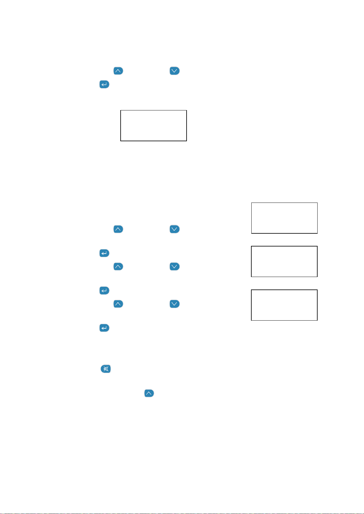
4.2.11 CLOCK SETUP (Series 500)
Select CLOCK SETUP under MONITOR SETUP, HOUR will display,
Use the scroll up and scroll down buttons until the correct hour is displayed
Press enter to confirm the change, MINUTES will display
Repeat steps for seconds, month, day and year
14:30:12
NOTE: The clock is a 24 hour clock (e.g. 14:30 = 2:30 pm)
4.2.12 LOGGING SETUP (Series 500)
The Series 500 monitor can log up to 8188 data points divided by the number of parameters being
logged. Parameters include; gas sensors, temperature and optional relative humidity sensor and for
the PM sensor PM2.5 and PM10 are treated as separate parameters.
Oct 07 12
Select LOGGING SETUP under MONITOR SETUP, LOG FREQ 1
MIN will appear on the display.
Use the scroll up and scroll down buttons to select the
required frequency in 1 minute intervals
Press enter to confirm the selection, CLEAR LOG will display
Use the scroll up and scroll down buttons to select YES
or NO
Press enter to confirm the selection, LOGGING will display
Use the scroll up and scroll down buttons to select ON or
OFF
Press enter to confirm the selection and return to the setup menu
Logging short cuts
The data log can also be cleared directly from the main display screen by holding down the
mute button for 2 seconds until the monitor beeps (if the monitor keys are not muted).
Data logging can also be both started and stopped directly from the main display screen by
pressing the scroll up button for two seconds until the monitor beeps (if the monitor keys
are not muted).
MRK-D-0022 V4 Aeroqual Series 200, 300 & 500 User Guide Page | 15
Page 16
Logging indicator
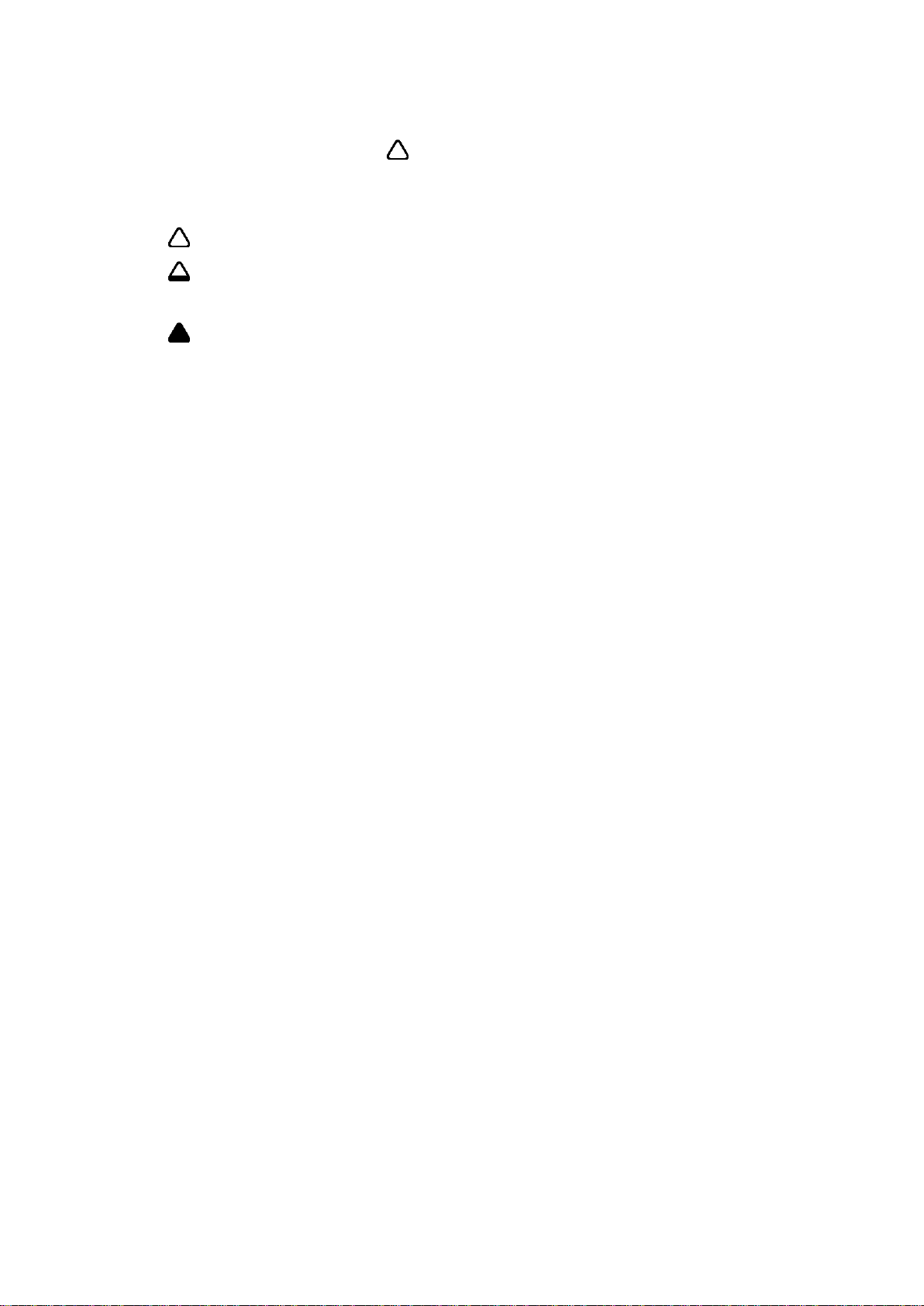
When data logging is initiated a triangle will appear on the main display screen. The triangle is an
indication that data logging is active, and is also used as an indication of the presence of data, as
below:
An empty triangle indicates that no data is stored
A filling triangle indicates that some data is stored in the memory. The triangle will fill up in
10% increments.
A full triangle indicates that the memory is full and needs downloading to the PC.
For direct logging to a PC using Aeroqual Monitor Software refer to Section 5.4.
MRK-D-0022 V4 Aeroqual Series 200, 300 & 500 User Guide Page | 16
Page 17
5 Aeroqual Monitor Software (Series 500)
Aeroqual Monitor Software for the Series 500 is available for free download from the Aeroqual
website: https://www.aeroqual.com/support/product-software
5.1 Computer Requirements
USB to monitor cable (supplied with the Series 500)
Window OS version 2000 or later required – iOS platforms are not supported
512 Mb RAM or more recommended
1 GHz processor speed or faster recommended
NOTE: S500 V6.5 software will support Series 500 monitors with firmware S500 V5.x, earlier
versions are incompatible.
5.2 Connect to Monitor
Connect the Series 500 monitor to a computer using the cable supplied and turn on
Launch the Aeroqual Monitor PC software and click on the toolbar to search for the
monitor. The unit will be detected automatically and connect
Test the connection by clicking on the tool bar. This will display the Monitor Name,
Version and ID Number
5.3 Monitor Setup
The Software can be used to setup the following on the Series 500 monitor:
Monitor ID
Location ID
Units
Logging Frequency
Output Sensor
Alarm Settings
Control Settings
Clock
To setup:
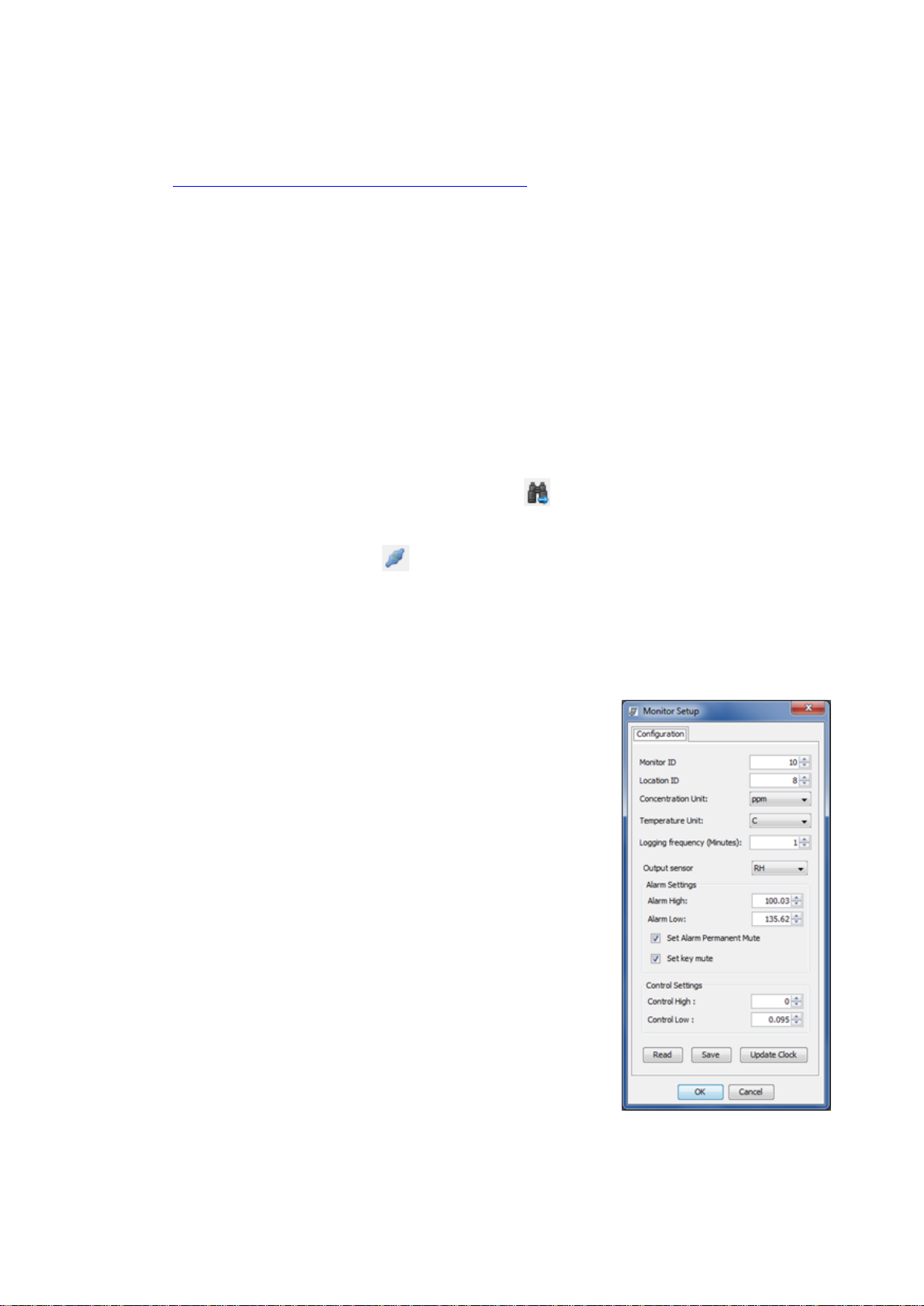
Monitor Setup (or Ctrl P), the Monitor Setup dialog box will
appear
Type in, or scroll up or down to set the desired values
Click the ‘Save’ button to synchronise the monitor values with
those on the PC
In order to log data it is essential that the clock on the monitor is
set to the real time. Click ‘Update Clock’. This can also be done
on the monitor (Section 4.2.11)
NOTE: If the temperature and humidity sensor is connected, an option to select Temperature unit will
appear.
MRK-D-0022 V4 Aeroqual Series 200, 300 & 500 User Guide Page | 17
Page 18
5.4 Data Logging
The Aeroqual Monitor Software can be used to log data directly from a Series 500 monitor to a PC.
For instructions on how to log data on the monitor itself, refer to Section 4.2.12.
5.4.1 PC Data Logging
Ensure that the USB cable is connected to the monitor and to the PC. Click File Start PC Data
Logging, or click on the toolbar. The data will be logged directly to the database on the PC. No
data will be stored on the monitor memory in this mode of operation. However, if PC data logging is
stopped by clicking on the toolbar, the data will start to be stored in the Series 500 monitor
memory.
5.4.2 Downloading Logged Data from Series 500
Logged data from the monitor memory can be downloaded by clicking File Download Logged
Data or by clicking on the toolbar. A data download progress bar will appear while the data is
downloading.
If for any reason, the data download does not complete, is terminated or stops:
Turn off the monitor to prevent any data loss.
Delete the data that has been downloaded to the PC
Close the PC software program and repeat the downloading process with the monitor on,
connected and with the PC software running.
NOTE: Downloaded data will not be removed from the monitor memory. To delete the logged data
from the monitor refer to Section 4.2.12.
5.4.3 Graphs
While logging directly to a PC, the Real Time View Graph or the Logged Data Graph can be
accessed via ‘Data’ on the menu bar. Logged data graph can be viewed be clicking Data
Graph Logged Data. Each parameter is shown in individual tabs.
To Configure graphs:
Graph Default Style or by right clicking
on the graph and selecting ‘Graph Style’
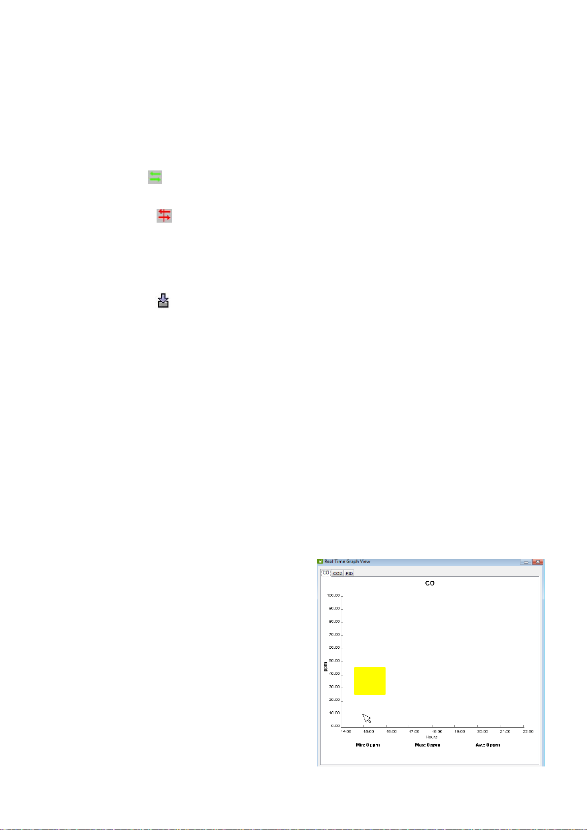
To zoom in:
Click on the graph and drag to create a yellow
rectangle. The yellow rectangle shows the
selected area the graph will zoom into.
To save graphs:
Right click on the graphs to save or print.
Graphs will be saved as a JPG file
To reset the graph to the default:
Right click and select ‘Reset to Default’
MRK-D-0022 V4 Aeroqual Series 200, 300 & 500 User Guide Page | 18
Page 19
In the Logged Data Graph the date, time and sensor type to be viewed can be selected. The Monitor
and Location ID can also be selected.
NOTE: The Monitor ID is not logged on each record in the monitor but will be stored in the database
against each measurement when the data is downloaded. The data will be tagged with
whatever the monitor ID is at the time of download. Conversely, the location ID is logged on
each record in the monitor.
5.4.4 Tables
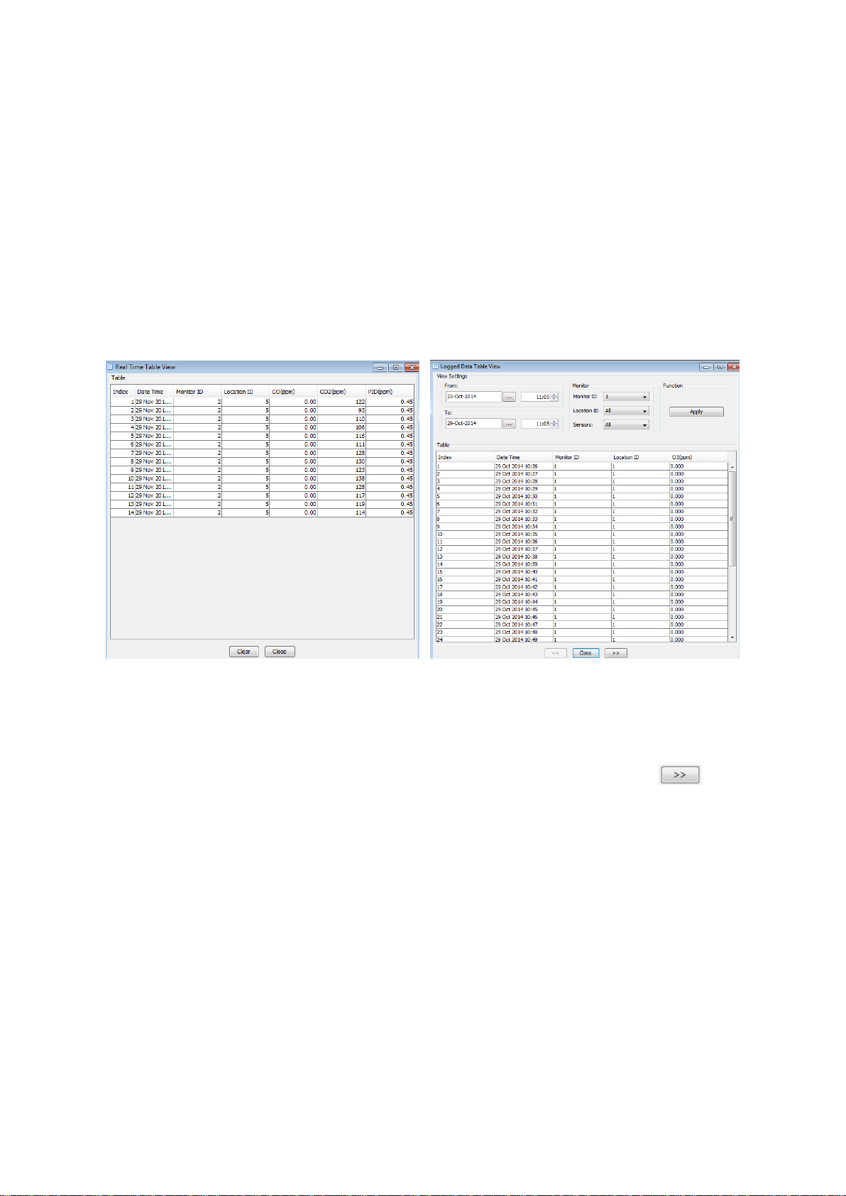
While logging directly to a PC, the Real Time Table View or Logged Data Table View can be
accessed via the Data menu on the menu bar.
In the logged data table view the date, time and sensor type can be selected to view the relevant data.
The Monitor and Location ID can also be selected. Once these parameters have been selected click
‘Apply’ to filter the data and display the selected parameters.
The logged data table will display up to 7 days of data on each page. Click the arrows at the
bottom of the table to view the previous or next 7 days of data within the filtered data set.
NOTE: Only one monitor ID can be viewed at a time in the logged data table view.
MRK-D-0022 V4 Aeroqual Series 200, 300 & 500 User Guide Page | 19
Page 20
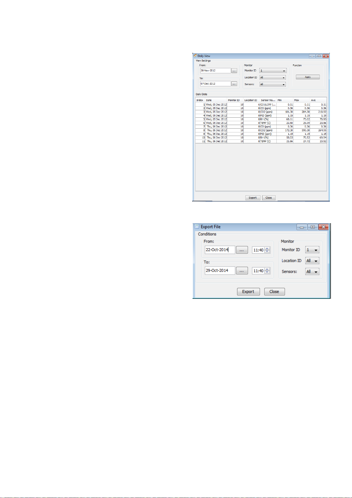
5.4.5 Daily View
This is a summary for each day, from midnight to
midnight, of the Minimum, Maximum and Average
readings over the 24 hour period. To launch the Daily
View window:
Data Daily Analysis
Select the date range, monitor and location ID
and click ‘Apply’ or click ‘View All’
Click ‘Export’ to export summary data files to
programs such as MS Excel.
NOTE: Only one monitor ID can be viewed at a time in
the daily view table.
5.4.6 Exporting Data
To export the database:
File Export Logged Data
Select the range of data to be exported using
the date, time, monitor ID, location ID and
sensor type parameters
Click ‘Export’, select a directory, choose a file
format (either plain text or MS Excel file)
Click ‘Save’ to export the data to the chosen
location
NOTE: Only one monitor ID can be exported at a time. Up to 50,000 lines of file can be exported at
once. If more than 50,000 lines need to be exported it will need to be carried out in two
exports.
MRK-D-0022 V4 Aeroqual Series 200, 300 & 500 User Guide Page | 20
Page 21
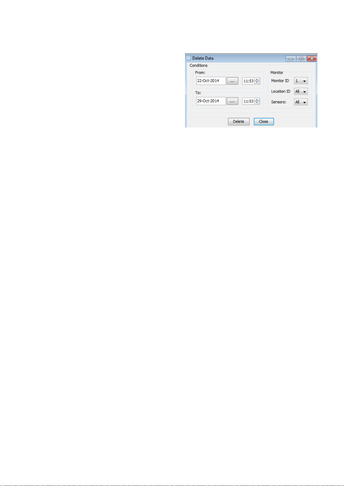
5.4.7 Deleting Data
To delete data in the database:
File Database Management Delete
Data.
Select the range of data to be deleted using
the date, time, monitor ID, location ID and
sensor type parameters
Click ‘Delete’. A warning notice will appear
confirming the data set to be deleted. Click
yes to delete the data.
NOTE: Only data from one monitor ID can be deleted at a time.
5.4.8 Zipping Data
To archive logged data:
File Database management Zip Database
Select a directory to back up all the current stored data to a zipped file.
To view archived logged data:
File Database management Unzip Database
Select the zipped file and click OK.
View and analyse data as required (Data Table Logged)
NOTE: Do not view archived data on the same PC being used for data logging; logging will be
stopped and the current data in the database will be lost unless it has been zipped.
MRK-D-0022 V4 Aeroqual Series 200, 300 & 500 User Guide Page | 21
Page 22
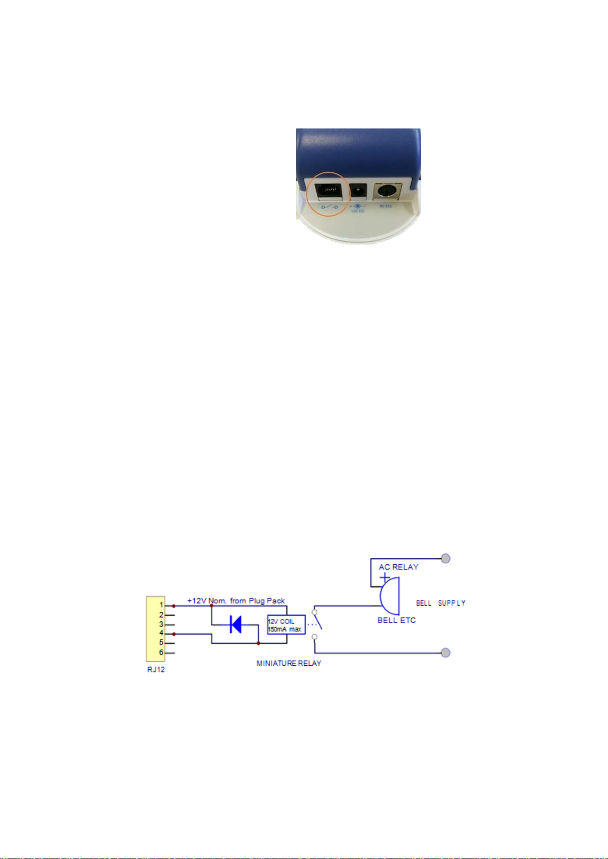
RJ12
connector
pin order
654321
6 External Control Wiring (Series 300 & 500)
The pin numbers for the external output connector are numbered from 1 to 6. Pin 1 is the closest pin
to the power jack.
The pin designations are as follows:
1. 12 V DC
2. Analogue output 0-5 V
3. Control
4. High alarm
5. Low alarm
6. Ground
The RJ12 connector offers two possibilities for wiring, either a switch to GND or a 12V output.
If the 12V output is used, the power for the relay coil is supplied by the Aeroqual AC/DC
adaptor. In this case, ensure that the relay coil does not draw more than 150mA and that a
protection diode is inserted across the relay coil.
If the switch to GND output is used, ensure that the relay coil does not draw more than
150mA, that the voltage does not exceed 24V and that a protection diode is inserted across
the relay coil.
6.1 Wiring for Alarm
The high alarm and low alarm pins can be wired to supply simple on / off switching to operate
equipment which requires only an on or off signal, such as an alarm.
To switch to GND, wire to pins 4, 5 and 6.
To switch to 12V output, wire to pins 4, 5 and 1
NOTE: Wiring for alarm will only operate while the Series 500 is powered by the AC adaptor.
The following diagram is a typical wiring for a high gas level alarm.
NOTE: Failure to insert a circuit protection diode will result in damage to the monitor if a voltage spike
is created by the relay.
MRK-D-0022 V4 Aeroqual Series 200, 300 & 500 User Guide Page | 22
Page 23
6.2 Wiring for Control
The control pin can be wired to supply control of a gas concentration between upper and lower
concentration limits. The upper and lower limits can be set by the user. The factory default settings
are dependent on the gas sensor head selected at time of purchase.
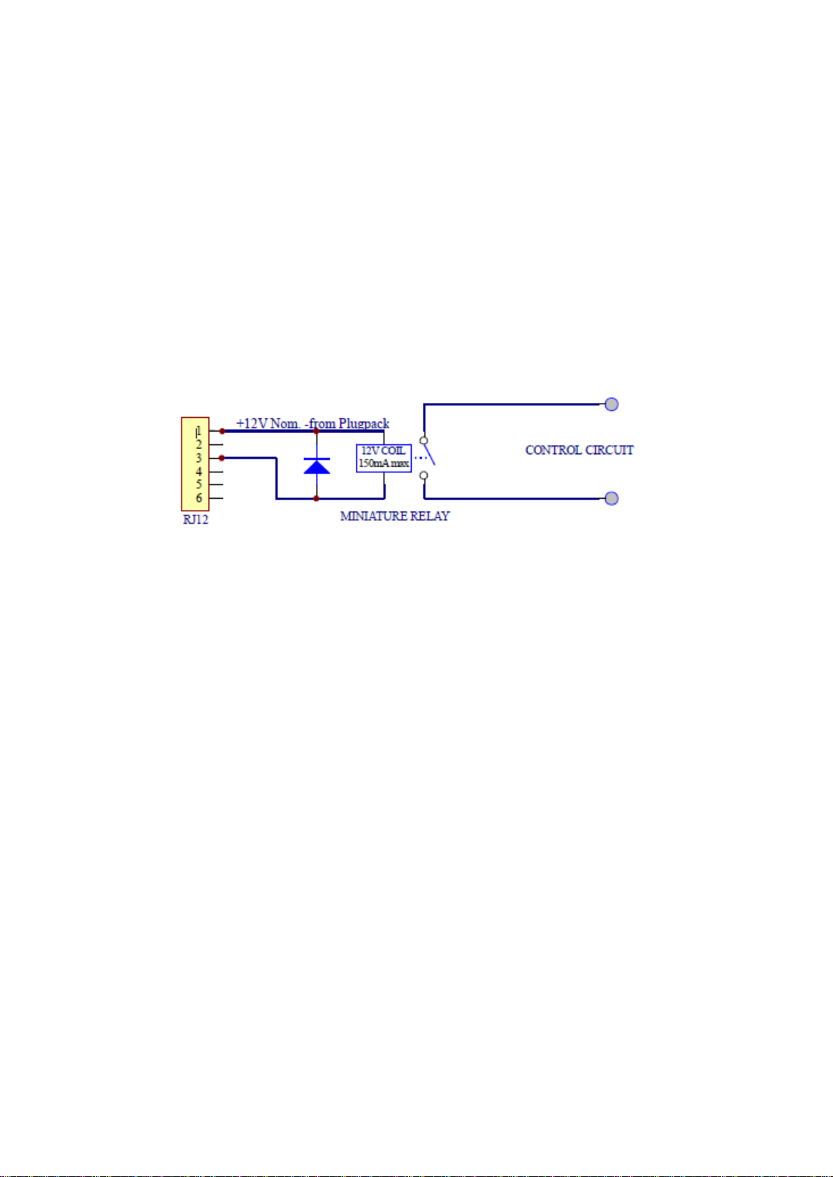
To switch to GND, wire to pins 3 and 6
To switch to 12V output, wire to pins 3 and 1
NOTE: Wiring for control will only operate while the Series 500 is powered by the AC adaptor.
Control is achieved by using a software latch. If power is lost to the monitor, the switch will open and
therefore turn off the external device connected to the monitor external output. The following wiring
diagram demonstrates the typical wiring to achieve the required control.
NOTE: Failure to insert a circuit protection diode will result in damage to the monitor if a voltage spike
is created by the relay.
6.3 Wiring the 0-5 V Analogue Output
The 0 to 5 V signal is a proportional signal based on the measurement of the selected output sensor.
The voltage out spans the specified gas sensor concentration range. For example: With the low
concentration ozone sensor head: 0 V represents 0 ppm ozone and 5 V represents 0.500 ppm ozone.
The ultra-low ozone sensor is a special case – 1.5V represents 0.150ppm ozone in this case.
Wire between pins 2 and 6
MRK-D-0022 V4 Aeroqual Series 200, 300 & 500 User Guide Page | 23
Page 24

7 Calibration
Aeroqual gas and particulate sensor heads can be calibrated in two ways:
1. Factory calibration – Gas and particulate matter (PM) sensors
Return sensors to Aeroqual for a multi-point calibration and new calibration certificate
Contact [email protected]
2. Manual calibration – Gas sensors only
Follow the calibration steps in the following sub-sections
In order to calibrate successfully the following equipment is required:
R42 Calibration Accessory (available from Aeroqual)
Inert tubing (Regulator to gas inlet) See table for gas/material compatibility
0.5 LPM constant flow regulator (e.g. Calgaz regulator model 715, flow rate 0.5 LPM)
Span gas in air cylinder
Zero grade air cylinder
7.1 Calibration FAQ's
What do I Calibrate, the monitor or the sensor head?
Aeroqual’s unique system of interchangeable sensor heads means they can be calibrated
independently of the monitor. If you are sending a sensor head to us for factory calibration, then you
do not need to send the monitor back. The monitor base does not need to be calibrated. Note: the
Series 300 and 500 monitor bases can be used to calibrate the zero and span of any sensor head
(including those from one of our fixed monitors); the Series 200 base can only be used for a zero
calibration.
How do I know my Sensor Head is reading accurately?
All our sensor heads come with a factory calibration certificate. Over time the sensor head will need to
be re-calibrated to ensure it is reading accurately. See below for a full discussion of how and when to
re-calibrate. In between calibrations, particularly when the monitor is being used for health and safety
purposes, a bump test is used to check the sensor is responding.
How do I do a bump test?
A bump test typically involves brief exposure of the sensor to a known quantity of gas and making
sure the monitor reading corresponds with that concentration. Unlike calibration there is no
adjustment of the monitor in response to the level of gas detected. For instructions on how to bump
test your handheld monitor refer to Section 7.4.
What is the difference between a zero and span calibration?
Zero calibration involves delivering a certified clean air (sometimes called zero air) source to the
sensor head and monitoring the response. If a non-zero reading is given, an adjustment is made so
that the monitor reports zero concentration.
A span calibration involves delivering certified calibration gas of a known concentration to the monitor
and monitoring the response to that concentration. An example might be delivering 10 ppm of Carbon
MRK-D-0022 V4 Aeroqual Series 200, 300 & 500 User Guide Page | 24
Page 25

Monoxide (CO) to the CO monitor. The response of the monitor to the calibration gas is adjusted so
that the monitor reads exactly the concentration of the span gas being delivered.
For instructions on how to zero and span calibrate your handheld monitor refer to Sections 7.5 and
7.6 respectively.
What is the difference between field and factory calibration?
As the name suggests factory calibration means calibration by the manufacturer or suitably qualified
laboratory. Field calibration involves calibration of the sensor head by the end user.
How do I calibrate my ozone sensor head in the field?
There is an important difference between ozone and other types of gases. Ozone cannot be stored in
bottles. Instead ozone must be generated at source using an ozone generator. A zero calibration can
be done using a zero air bottle, but for a span calibration you must be able to generate ozone. If you
have an ozone generator/calibrator then instructions on field calibration can be found in Section 7.6. If
you do not have an ozone generator/calibrator then we recommend sending the ozone sensors for
factory calibration (see below). Note: this applies for our PERC sensor heads too, because PERC is
only available as a solvent.
How do I calibrate my non-ozone sensor head in the field?
For non-ozone sensors, instructions on field calibration using calibration gas can be found in Section
7.6. watch a video demonstration of a gas sensor head calibration here: https://vimeo.com/76908258
How often do I need to field calibrate my sensor head?
This depends on the level of rigor required in your measurement application. Researchers may
calibrate before every measurement they take. But for most people regular calibration is enough to
ensure good results. By regular we mean once or twice per year. For the reasons of cost and
complexity outlined above, customers tend to calibrate ozone sensor heads less often and instead
send them to the manufacturer or laboratory once every year or so.
How do I factory calibrate my sensor head?
Simply send the sensor head to us or a suitably qualified laboratory. Our charges for factory
calibration are quite reasonable. Please contact us for a quotation.
How often do I have to factory calibrate my sensor head?
If you’re able to field calibrate your sensor head you may never need to send it to us for calibration.
However if you want to be 100% sure of the calibration, an annual factory calibration complete with
certificate provides ultimate peace of mind. Ozone sensors are hard to calibrate in the field so we
recommend sending for factory calibration once every year.
What is the expected lifetime of my sensor head?
This is hard to answer as it depends on the type of sensor and the application it used in. As a guide
assume your sensor will last two years, however higher exposure levels or harsh environments can
MRK-D-0022 V4 Aeroqual Series 200, 300 & 500 User Guide Page | 25
Page 26
1 23
lead to a significant reduction in life expectancy. Your monitor display is likely to indicate “Sensor
Failure” or “Sensor Ageing” if the sensor is nearing the end of its useful life.
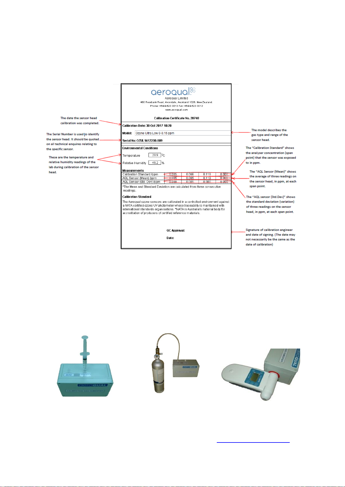
7.2 Calibration Certificate
7.3 Calibration Accessory
Aeroqual’s Calibration Accessory (P/N R42) facilitates humidity control and delivery of calibration gas
to the sensor head. Follow the steps below to prepare the Calibration Accessory for zero or span
calibration of a sensor head.
1. Fill R42 Calibration Gas Accessory with 5g of water with water syringe via water inlet.
2. Connect cylinder and regulator to R42 gas inlet via tubing and Luer attachment.
3. Insert warmed up sensor head (mesh cover end) into the outlet of the R42 as shown below.
NOTE: The R42 cannot be used for the calibration of NH3 and PERC, these sensors need to be
returned to Aeroqual for calibration.
Watch a video demonstration of a gas sensor head calibration here: https://vimeo.com/76908258
MRK-D-0022 V4 Aeroqual Series 200, 300 & 500 User Guide Page | 26
Page 27

7.4 Bump Test
Operators may wish to have increased confidence in the operation of their monitor by performing a
bump test prior to taking measurements.
A bump test involves quickly exposing the sensor to span gas and confirming the sensor indicates an
elevated response. The equipment for performing a bump test is the same as for performing a span
calibration, however it is not necessary to wait for the monitor to warm up before performing a bump
test, nor is it necessary to wait for the monitor readings to stabilize to confirm a successful bump test.
Turn on the monitor and place it at the outlet of the R42, you will need to wait three minutes before
readings will be displayed on the monitor. Turn on the span gas and observe the sensor reading, the
reading should quickly elevate above the baseline reading and approach that of the span gas
concentration. If the reading does not approach that of the span concentration this could indicate a
monitor fault or the need to perform a calibration. Once an elevated reading has been observed close
to the span gas concentration the gas can turned off, you must then wait for the readings to come
down to baseline level before taking measurements.
7.5 Zero Calibration
Under some circumstances, sensors may temporarily exhibit a baseline reading higher than zero due
to insufficient warm-up, or cross-sensitivity to other gases. In this case it is worthwhile checking
against a standard zero air source.
7.5.1 Zero Calibration Procedure
Follow the initial set up instructions in Section 7.3, then proceed as follows:
Flow zero air until the reading stabilises (about 10 minutes)
Initiate ZERO CAL on the monitor, see Section 4.2.1:
Series 200: Press and hold until the word ZEROING appears next to ZERO CAL. The
routine will run for up to ten minutes (depending on the gas sensor installed) and then beep to
indicate completion.
Series 300 and 500: Enter the CALIBRATE menu by pressing the and buttons for 2
seconds, then select ZERO CAL then:
Single gas heads: Toggle YES/NO using the buttons, select YES then press .
The word ZEROING appears, the zero routine will run for up to ten minutes (depending on the
gas sensor installed) and then beep to indicate completion.
PM sensor head and T/RH probe: Press to bring up the OFFSET for the sensor head.
Use the buttons to change the OFFSET and press to accept. Calculate the new
OFFSET using the equation below:
New OFFSET = (Sensor Reading/GAIN) + Old OFFSET
NOTE: Offsets are stored on the sensor, Temp/RH offsets are stored on the monitor.
MRK-D-0022 V4 Aeroqual Series 200, 300 & 500 User Guide Page | 27
Page 28

Aeroqual Sensor Head
Suggested span point 80 %
Full Scale (in a balance of air)
Tubing material for
gas calibration
Carbon Monoxide 0-25 ppm
20
Tygon R-3606
Carbon Monoxide 0-100 ppm
80
Tygon R-3606
Carbon Monoxide 0-1000 ppm (leak)
800
Tygon R-3606
Carbon Dioxide 0-2000 ppm
1600
Tygon R-3606
Carbon Dioxide 0-5000 ppm
4000
Tygon R-3606
Nitrogen Dioxide 0-1 ppm
0.8
PTFE (Teflon)
NH3 0-100ppm
Factory calibration required
-
NH3 0-1000ppm (leak)
Factory calibration required
-
Hydrogen 0-5000 ppm
4000
PTFE (Teflon)
H2S 0-10 ppm
8
PTFE (Teflon)
H2S 0-100 ppm
80
PTFE (Teflon)
Methane 0-10000 ppm
8000
PTFE (Teflon)
Ozone (OZU) 0-0.15 ppm
0.12
PTFE (Teflon)
Ozone (OZL) 0-0.5 ppm
0.4
PTFE (Teflon)
Ozone (OZG) 0-10 ppm
8
PTFE (Teflon)
PERC 0-200 ppm
Factory calibration required
-
SO2 0-10 ppm
8
PTFE (Teflon)
SO2 0-100 ppm
80
PTFE (Teflon)
VOC (Isobutylene) 0-25 ppm
20
PTFE (Teflon)
VOC (Isobutylene) 0-500 ppm
400
PTFE (Teflon)
NMHC (Isobutylene) 0-25 ppm
20
PTFE (Teflon)
PID (Isobutylene) 0-20
16
PTFE (Teflon)
PID (Isobutylene) 0-1000
800
PTFE (Teflon)
7.6 Span Calibration (Series 300 and 500)
Span calibration provides an option to adjust the GAIN of Aeroqual sensor heads.
There are no optimum span concentrations for calibrating Aeroqual sensor heads. There are however
a few considerations which can guide the decision as to which span concentration is most
appropriate.
For the majority of uses, gases will be purchased for calibration at the concentration to be used for the
span calibration, rather than purchased at high concentrations and diluted using a gas dilution
calibrator. Therefore users may find some restrictions on what concentrations can be provided by
their chosen calibration gas supplier.
For some applications measurements will be made close to the monitor’s maximum detection limit.
For these applications a span point at 80 % of full scale is suggested. For other applications, gas
levels may be important across a broad range rather than just close to the maximum exposure limit.
Other applications may make more use of the lower end of the sensors working range, with higher
levels occurring less frequently and having less importance. The most appropriate span point will thus
depend upon the intended application. If the intended application is not known, Aeroqual suggests a
span point at 80 % of full scale. All gases should be purchased in a balance of air.
MRK-D-0022 V4 Aeroqual Series 200, 300 & 500 User Guide Page | 28
Page 29

7.6.1 Span Calibration Procedure
IMPORTANT
Always point the cylinder and regulator away from yourself and others when attaching or
removing a pressure regulator.
Always secure the cylinder to prevent it from being knocked over while the regulator is attached.
Follow the initial set up instructions in Section 7.3, then proceed as follows:
Flow the target gas at 0.5 LPM
Measure the gas concentration on the monitor screen and wait for it to stabilise (10 minutes).
If the Aeroqual sensor head requires a span adjustment then enter the CALIBRATE menu by
pressing the and buttons simultaneously for 2 seconds. Then select SPAN CAL and
change the GAIN using the scroll buttons. Calculate the new GAIN using the equation below:
New GAIN = Old GAIN x (Span Gas Concentration (ppm) / Sensor Reading)
NOTE: Temp/RH GAIN are stored on the handheld not on the sensor. Other GAIN are stored on the
sensor.
7.7 Health and safety during calibration
Upmost care must be taken while performing a zero or span calibration. Cylinder gas can cause harm
in a number of ways. There a number of sources of good information about the correct use and
storage of compressed gases.
The following resources may prove useful:
The National Institute for Occupational Safety and Health:
http://www.cdc.gov/NIOSH/
The United States Department of Labour
http://www.osha.gov/SLTC/compressedgasequipment/index.html
The following information is a guide for what to consider when handling compressed gas but Aeroqual
recommends operators adhere to their local regulations regarding compressed gas handling.
7.7.1 High pressure leak or failure of pressure regulator
Many calibration gases are held in cylinders at high pressure in excess of 1000 Psi. Incorrectly fitting
the pressure regulator, using a regulator which is faulty or knocking the cylinder over while the
regulator is attached can cause physical harm from high speed projectiles resulting from a high
pressure leak from or failure of the regulator.
It is important to always fit a high quality undamaged pressure regulator to the gas cylinder and that
the regulator type is suitable for the cylinder you are attaching it to.
Always use protective eyewear (safety glasses) when working with compressed gas.
MRK-D-0022 V4 Aeroqual Series 200, 300 & 500 User Guide Page | 29
Page 30
7.7.2 Flammability of combustible gases
Calibration gas can be stored in cylinders at high concentrations and can this can present a hazard if
those gases are combustible. The lower explosive limit (LEL) is the lowest concentration of gas at
which combustion will be sustained in air if an ignition source (spark or flame) is present. The LELs for
the gases used for calibrating Aeroqual sensor heads are all significantly above the calibration span
points so this risk is low. It is important however that the LEL be known for the gas being employed
and that suitable precautions be taken to further minimize the risk from explosive combustion such as
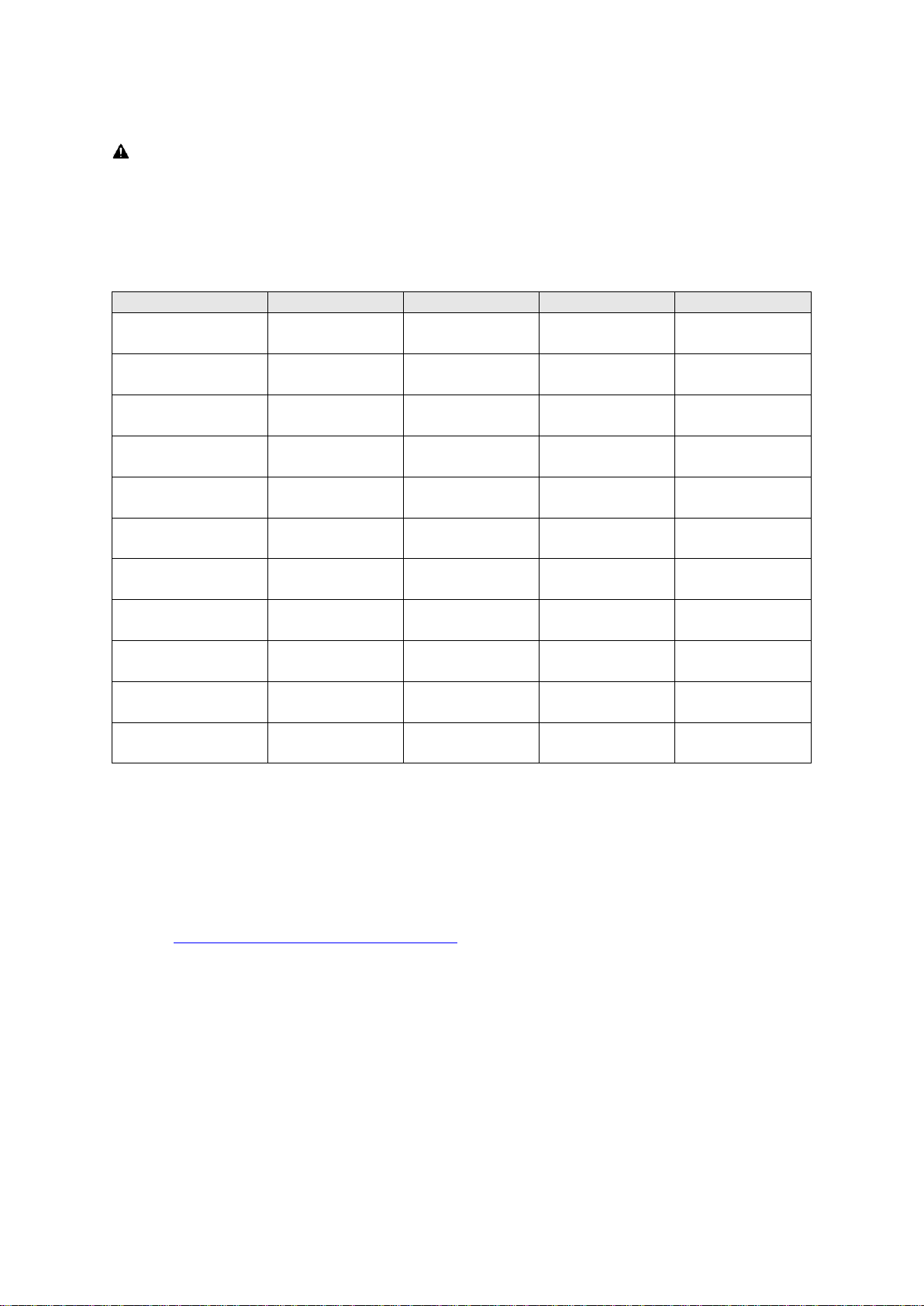
performing the calibration in a fume hood. The table below lists the LELs for the gases used to
calibrate Aeroqual’s sensor heads.
7.7.3 Toxicity
While most of the recommend span points fall below the Immediately Dangerous to Life or Health
(IDLH) limits published by the National Institute for Occupational Health and Safety (NIOSH), some
span points are above these limits and therefore it is crucial that rigorous health and safety
procedures be followed during calibration to avoid exposure to the calibration gas.
IDLH concentration limits as well as concentration limits for longer exposure times are listed in
Section 7.7.4
The LDLH limits are known for most of the gases of concern, however there are some gases for
which data are not available. In these cases gases should be considered as being toxic and handled
as such. Health and safety data are often revised, Aeroqual recommends checking external sources
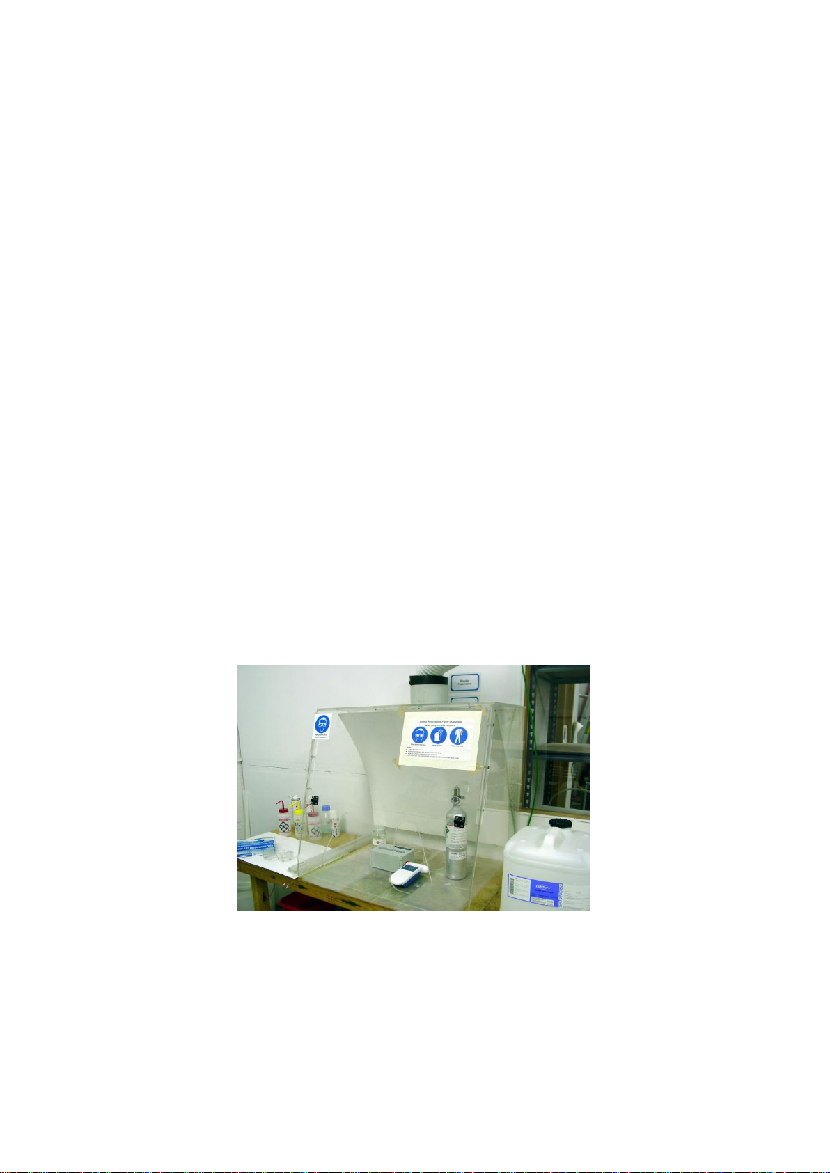
for the most up to date information. Aeroqual suggests that all span calibrations be performed in a
fume hood such as the one in the image below to avoid exposure to personal.
MRK-D-0022 V4 Aeroqual Series 200, 300 & 500 User Guide Page | 30
Page 31
Gas
IDLH (ppm)
PEL (ppm)
STEL (ppm)
LEL (ppm)
Carbon Monoxide
1200
25
N/A
125,000
Carbon Dioxide
40000
5000
30000
N/A
Nitrogen Dioxide
20
N/A 1 N/A
Ammonia
300
25
35
150,000
Hydrogen
N/A
N/A
N/A
40,000
Hydrogen Sulfide
100
10
15
40,000
Methane
N/A
N/A
N/A
50,000
Ozone 5 0.1
0.3
N/A
PERC
150
N/A
N/A
N/A
Sulphur Dioxide
100 2 5
N/A
Isobutylene
N/A
N/A
N/A
18,000
7.7.4 IDLH Concentration Limits
IMPORTANT
The information below is provided as an indication only. Please check for the latest information or
local guidelines as values may vary by jurisdiction.
Always use protective eyewear (safety glasses) when working with compressed gas.
IDLH Immediately Dangerous to Life or Health
PEL Permissible exposure limit (usually based upon a time weighted 8 hour average
STEL Short - term exposure limit (1 hour average)
LEL Lower explosion limit
Source: http://www.cdc.gov/niosh/idlh/intridl4.html
MRK-D-0022 V4 Aeroqual Series 200, 300 & 500 User Guide Page | 31
Page 32
Gas measurement units
ppm or mg/m3
Reading functions
Minimum, maximum, average
Sensor head
Interchangeable, replaceable
Display type
LCD
Display status indicators
Battery, sensor, standby, mute, high/low alarm,
monitor ID, location ID.
Sensor calibration features (S300 S500)
Zero and span via secret menu
Power supply
12V DC (power adaptor/charger supplied 100250V AC)
Rechargeable battery
Ni-MH 9.6V DC | 2100mA/h or Lithium 11.1V
Temperature & Humidity sensor
Temp: -40°C to 124°C; RH: 0 to 100%
Size (with sensor head)
195 x 122 x 54 (mm)
Weight (with sensor head and battery)
< 460 g
Environmental operating conditions
Temperature: -5 °C to 45 °C
Humidity: 0 to 95% non-condensing
Enclosure material and rating
PC and ABS; IP20 and NEMA 1 equivalent
Audible Alarm (S300 & S500)
Low alarm, high alarm
External transistor outputs for alarms &
control (S300 & S500)*
12 VDC or switch to GND (150 mA max)
Analogue output (S300 & S500)
0-5V
Digital interface (S500)
RS232 with USB converter
Data logging capacity (S500)
8188 data points in total
PC data logging (S500)
Software and data cable supplied
Clock function (S500)
Real time
Approvals
Part 15 of FCC Rules
EN 50082-1: 1997
EN 50081-1: 1992
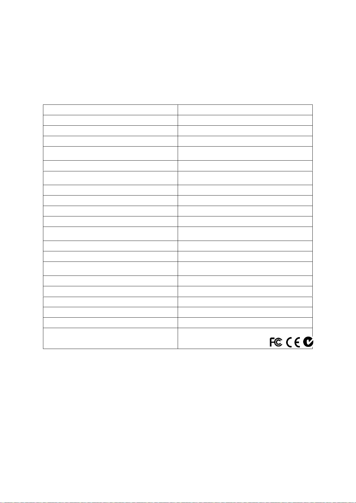
8 Specifications
The Aeroqual handheld monitors have been specifically designed to incorporate Aeroqual’s in-depth
knowledge of accurate ambient gas measurement and can be used with a wide range of gas sensor
heads. The sensor heads are interchangeable and therefore multiple heads can be used on the same
base unit. The sensors are calibrated prior to delivery.
*All of the transistor outputs are open collector current sink. The maximum rating of these transistor
outputs is 12VDC at 150mA. If you connect a relay or any other inductive load to the transistor
outputs, a back EMF suppression diode must be fitted across the load.
Aeroqual accepts no responsibility for damage to this product or any other issues arising from the
non-compliance with the above directives. Failure to implement these directives will invalidate the
warranty on this product.
MRK-D-0022 V4 Aeroqual Series 200, 300 & 500 User Guide Page | 32
Page 33
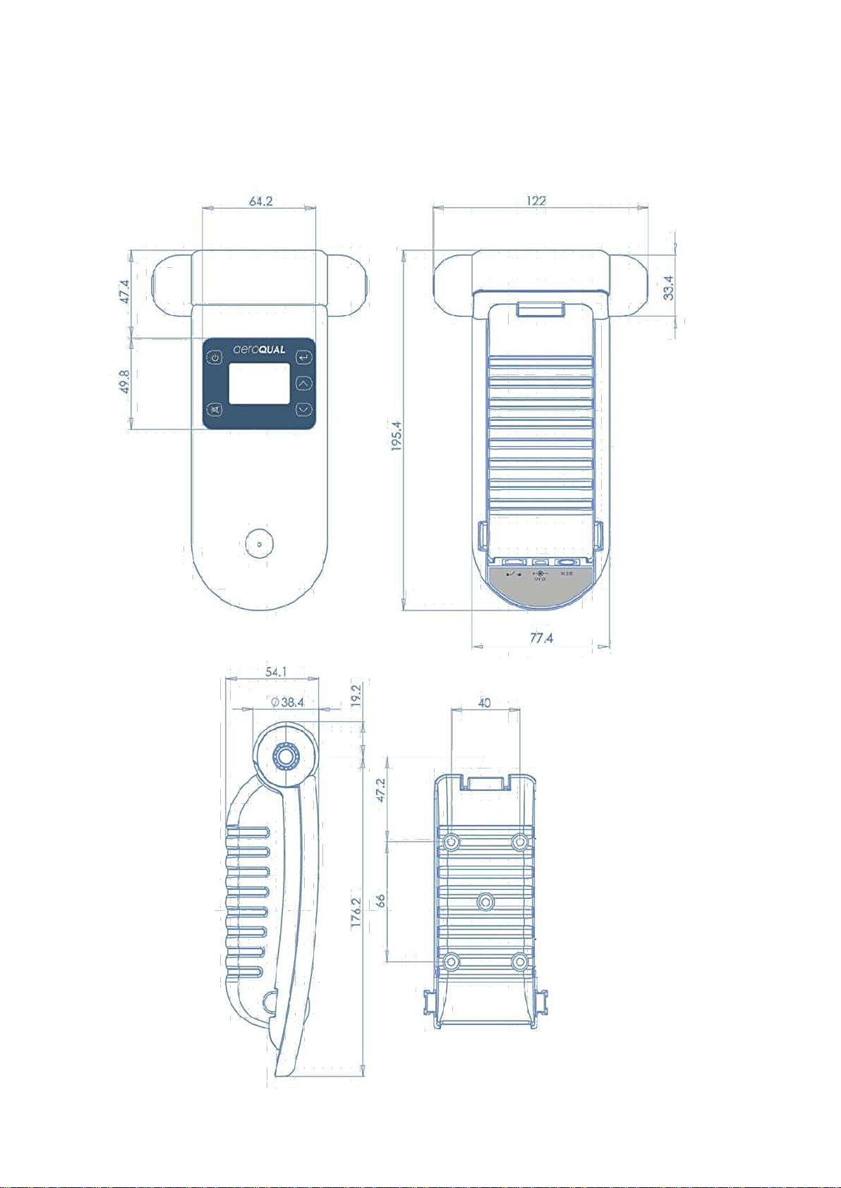
8.1 Dimensions
MRK-D-0022 V4 Aeroqual Series 200, 300 & 500 User Guide Page | 33
Page 34
Dimensions
Value
Height (including cable gland)
283 mm
Width
180 mm
Depth
90 mm
Materials
Fibre-glass reinforced polycarbonate base
Polycarbonate lid
Mounting
Screw fixture
Operating temperature
-35°C to 120°C
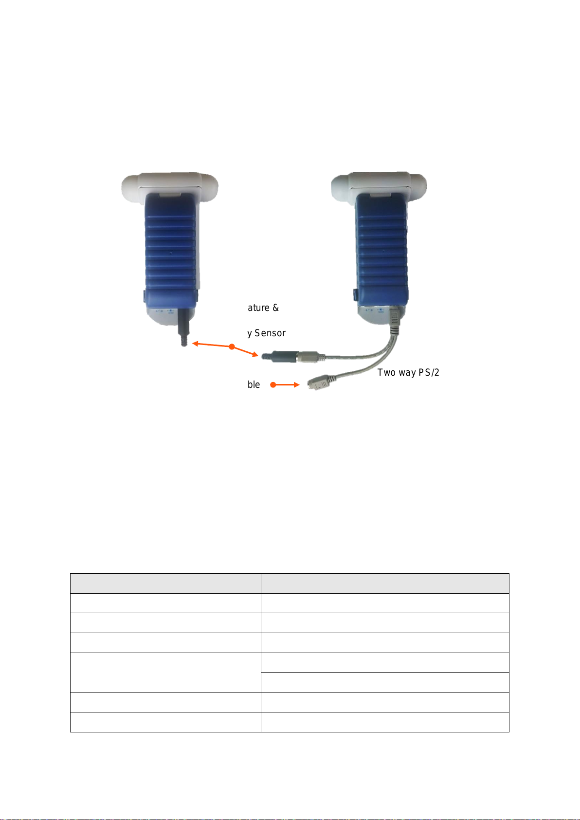
Monitor to USB connection cable
Two way PS/2 adaptor cable
Temperature &
Relative
Humidity Sensor
9 Optional Accessories:
9.1 Temperature and Relative Humidity Sensor (HH TRH)
If the temperature and relative humidity sensor has been purchased, it can be inserted into the PS/2
connector at the base of the monitor. Ensure monitor is turned off before connecting the sensor.
NOTE: The monitor will still operate with only the temperature and RH sensor connected.
9.2 Handheld Enclosure (HH ENC)
The handheld FRP enclosure is designed for fixed or secure monitoring. The inlet nozzles are
specifically designed to eliminate dust and reduce water ingress whilst minimising destruction of part
per billion gas concentrations or measurement variations due to outgas contamination from the
enclosure.
NOTE: Sensor heads fitted to this product must be Type 2 sensor heads that have fitted connectors
and are specifically calibrated to factor in the longer flow path. See sensor head variants in
Section 3.2
MRK-D-0022 V4 Aeroqual Series 200, 300 & 500 User Guide Page | 34
Page 35
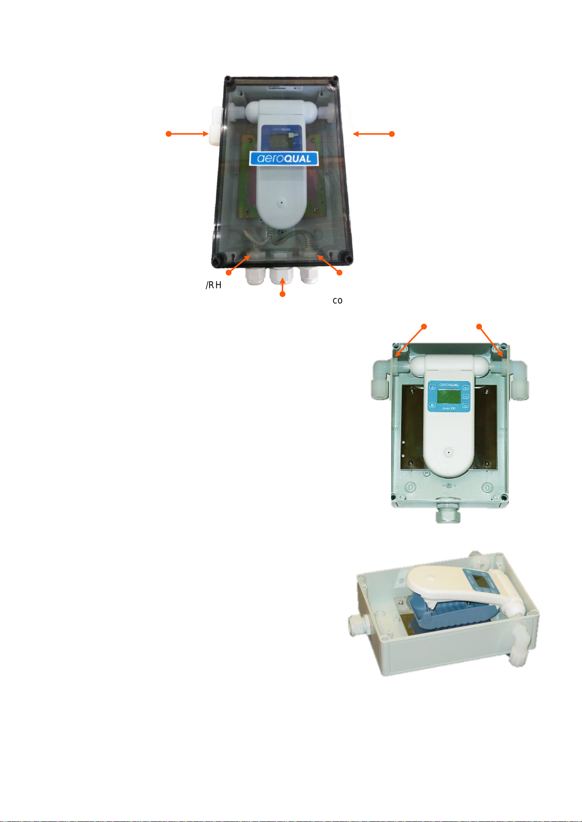
Temp/RH
sensor
Data logging
connection
Power connection
Lock Nuts
9.2.1 Replacing the Sensor Head
Using a flat headed screw driver undo the four lid screws at
each corner and remove the lid
Undo the lock nuts on either end and remove the inlet and
outlet nozzles and remove the sensor head by carefully
pulling it upwards, disconnecting it from the monitor
Replace the sensor head with another Type 2 sensor –
see Section 3.2
Re-insert the nozzles and tighten using the lock-nuts,
ensure there is a tight fit against the sensor head
Replace the lid and tighten the four lid screws
9.2.2 Removing the Monitor
Undo the four lid screws at each corner using a flat
headed screw driver and remove the lid
Loosen the lock nuts (see image above) on either
end of the sensor head and disconnect the inlet and
outlet elbows from the sensor head
MRK-D-0022 V4 Aeroqual Series 200, 300 & 500 User Guide Page | 35
Disconnect connections at the bottom of the monitor:
power, temp/RH sensor, data logging
Push in the blue plastic clips on either side of the
monitor unit to release the monitor
Carefully remove the monitor and sensor from the enclosure
Reverse the process to reconnect the monitor back onto the battery cover
Page 36
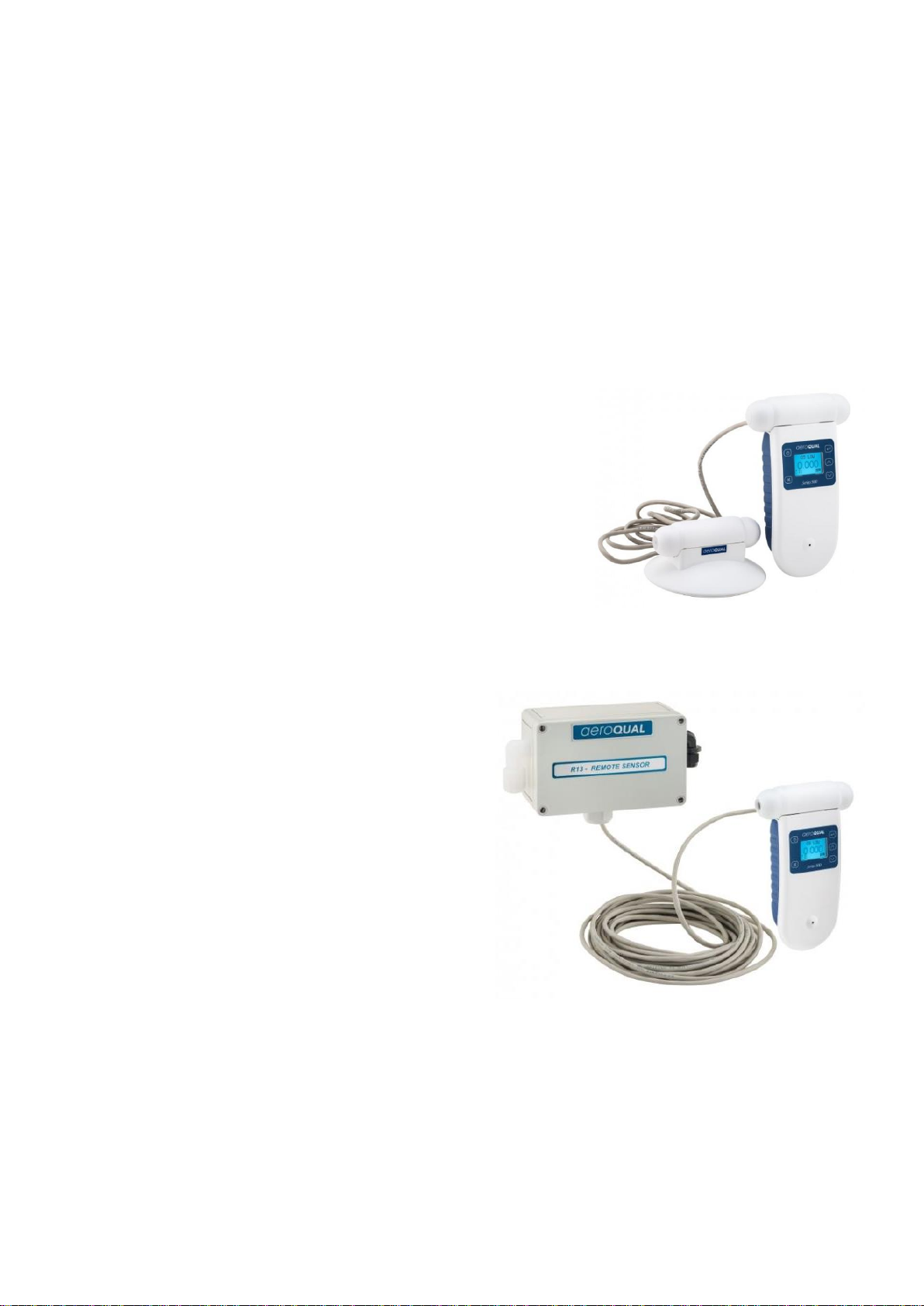
9.3 Remote Sensor Head Adaptors (AS R10 / AS R13)
The AS R10 and AS R13 are designed for remote monitoring away from the monitor base. They are
both compatible with the portable monitor (Series 200/300/500) and fixed monitor (Series 900/930)
range of instruments.
The AS R10 is the basic option with 2 m of CAT5 cable, the AS R13 is an IP41 rated option providing
additional protection to compatible sensor heads, and comes with 10 m of CAT5 cable.
NOTE: Up to 14m of CAT cable can be used for connection.
9.3.1 Connecting the IP20 / NEMA 1 Remote Sensor Head Adaptor (AS R10)
The AS R10 comes with a circular base, a sensor adaptor and 2 m
CAT5 cable.
Connect the sensor adaptor into the portable or fixed
monitor base
Connect the gas sensor head into the circular base
Plug each end of the CAT5 cable into the circular base and
sensor adaptor
The monitor base can now be turned on and measurements
taken
9.3.2 Connecting the IP41 / NEMA 2 Remote Sensor Head Adaptor (AS R13)
The AS R13 comes with an IP41 rated enclosure, a
sensor adaptor and 10 m of CAT5 cable
Connect the sensor adaptor into the portable
or fixed monitor base
Connect the gas sensor head inside the IP41
rated enclosure. Ensure the nozzles are
tightly secured on the inlet and outlet of the
sensor head
Plug each end of the CAT5 cable into the
IP41 rated enclosure and the senosr adaptor.
Ensure sure the cable gland on the IP41 is
tightened securely
The monitor base can now be turned on and measurements taken
NOTE: The IP41 rated enclosure is only compatible with the Type 2 sensor heads – see Section 3.2.
MRK-D-0022 V4 Aeroqual Series 200, 300 & 500 User Guide Page | 36
Page 37

Fault Description
Possible cause
Remedy
No power
Lead connection broken
Power supply failure
Battery flat
Unit damaged
Sensor head damaged
Reconnect power lead
Replace 12V DC power supply
Recharge battery
Replace unit
Replace sensor head
Sensor failure when
the sensor is new
Insufficient warm-up
Air contaminated
Sensor damaged
Run the sensor on full power for 2448 hours. If using an ozone sensor
head and an O3 source is available,
exposure to 100 ppb for 5 minutes
will speed up the decontamination
process
(approximately 30 minutes)
Move the sensor to cleaner
environment and check reading
Replace sensor
Reading high under
zero gas conditions
Background gas level higher
than normal
Interfering gas present
Sensor zero drift
Sensor damaged
Move sensor to clean air and
check reading is zero or close to
zero
Move sensor to clean air and
check reading is zero or close to
zero
ZERO CAL sensor zero grade air
using R42
Replace sensor
Reading higher than
expected in the presence of
sensor gas
Sensor correct
Interfering gas present
Sensor calibration lost
Check calibration of gas generator.
Move sensor to clean air and check
reading upon exposure to known
gas concentration
Replace /refurbish sensor
Reading lower than
expected reading in the
presence of
sensor gas
Sensor correct
Sensor inlet contaminated
Sensor fan failed
Check calibration of gas generator
Clean sensor inlet filter and mesh
Replace sensor
10 Troubleshooting
MRK-D-0022 V4 Aeroqual Series 200, 300 & 500 User Guide Page | 37
Page 38

Fault Description
Possible cause
Remedy
Interfering gas present
Gas reactive and decomposing before detection
Local air flow too high (ozone
sensors) or too low (VOC
and
ammonia sensors)
Sensor calibration lost
Move sensor to clean air and check
reading upon exposure to known
gas concentration
Move the monitor closer to them
source of the gas
Modify the airflow into and around
sensor head.
Replace /refurbish sensor
Reading unstable
Power supply unstable
Power supply current rating
incorrect
Local air flow too high
Environmental conditions
fluctuating
EMI noise picked up via USB
cable and PC (S500 unit
only)
Install stable power supply
Install power supply with correct
rating
Reduce air flow
Reduce fluctuations
Unplug cable to determine if this
reduces the instability. If this solves
the problem then isolate the power
on PC
External alarm and control
doesn't work correctly
(Series 300 and 500 units
only)
Incorrect RJ12 pins used
No diode across external
relay coil
Diode polarity incorrect
Check pins and wire correctly
Fit diode across external relay coil
Fit diode correctly
USB communications
unstable (S500 only)
Connections broken
COM Port settings incorrect
Clock setting incorrect
Reconnect leads
Setup COM port correctly
Synchronise clock with PC. If this
does not work then the Monitor clock
battery may be flat. Return monitor
to Aeroqual for battery replacement.
If after troubleshooting you are unable to resolve the problem, contact [email protected].
Please ensure serial numbers of the base and/or affected sensor/s are included in your email.
MRK-D-0022 V4 Aeroqual Series 200, 300 & 500 User Guide Page | 38
Page 39

Fault
Description
LCD Screen
0-5V
Output
(S300 &
S500 only)
Control
Output
(S300 &
S500
only)
Low
Alarm
Output
(S300 &
S500
only)
High
Alarm
Output
(S300 &
S500
only)
Data
Logging
(S500
only)
No Fault
Valid gas
reading
Reading
proportional
to gas
reading
As set by
user
As set by
user
As set by
user
Valid gad
reading
Sensor Failed
Fault
Sensor failure
5 V
Open
Closed
Closed
9999
Sensor Aging
Fault
Valid gas
reading +
sensor aging
Reading
proportional
to gas
reading
As set by
user
As set by
user
As set by
user
Valid gad
reading
Communications
Failure
SENSOR
NOT
CONNECTED
or N.C. or
turn off when
use Ni-MH
battery only
0 V
Open
Open
Open
No output
Sensor Standby
Standby
symbol
0 V
Open
Open
Open
No output
10.1 Sensor Failure
The handheld monitors have inbuilt diagnostics to detect sensor faults. If the sensor fails it can be
easily replaced by simply removing and installing a new one. The failed sensor can be sent back to
Aeroqual for refurbishment or disposal. Monitor status conditions are as follows:
11 Technical Support
Technical information, service and spare parts are available through your distributor. In addition,
worldwide technical support is available from Aeroqual Ltd.
Aeroqual Limited
460 Rosebank Road, Avondale, Auckland 1026, New Zealand
Phone: +64 9 623 3013
Fax: +64 9 623 3012
Email: [email protected]
MRK-D-0022 V4 Aeroqual Series 200, 300 & 500 User Guide Page | 39
Page 40

12 Care and Maintenance
Your Aeroqual Monitor is a product of superior design and quality and should be treated with care.
When using your Aeroqual Monitor:
Keep it and all its parts and accessories out of the reach of small children.
Keep it dry. Avoid water and/or condensation as humidity and liquids may damage sensitive
electronics and the Li battery.
Do not use or store in dusty, dirty areas.
Do not store the monitor in temperatures below 10°C or above 35°C.
This unit is designed for use at temperatures between -5°C and +45°C however please consult
recommended operating temperature for the sensor head which may be different. Avoid sudden
changes in temperature which may cause condensation that can damage the electronics.
Do not attempt to open. Non-expert handling of the device may cause damage.
Do not drop, knock or shake as this could lead to internal damage.
Do not use harsh chemicals, cleaning solvents or strong detergents for cleaning. Wipe with a soft
cloth slightly dampened with a mild soap-and-water solution
In order to maintain measurement accuracy, Aeroqual recommends that users replace or
refurbish their sensor heads on a yearly basis or more often if measurement certainty is
critical for your application. Please contact your dealer or Aeroqual.
12.1 Disposal / Recycling
Please note that this is an electronic product and disposal should be in line with your local or country
legislation. The plastic casing of the product is made from a Polycarbonate / ABS blended material
(PC + ABS) and is marked accordingly.
MRK-D-0022 V4 Aeroqual Series 200, 300 & 500 User Guide Page | 40
Page 41

Heavier than air*
Near the ground
No lower than 457 mm (18 inches),
and in some cases, no higher than 914 mm (36 inches)
Lighter than air*
Near ceiling, roof or out-take fan
13 Appendix
13.1 General Guidelines on the Measurement of Gases
A key factor in reliable leak detection is to locate the sensor between the potential leak source and the
ignition site or location of people. Sensors do not detect in a dispersive manner. They rely on single
point monitoring. The leak must reach this single monitoring point, in order to be detected. This is
precisely the reason why the sensor location and number of sensor installed is of utmost importance.
Sensor height
Mount the sensor at the appropriate height for the density of gas you wish to detect.
*Air currents often result in inconsistent air circulation. Always be aware of areas that could facilitate
irregular air currents and abnormal build-ups of gas (gas pockets).
Gas and vapour dispersion
Sensor installation should be near the potential leak source. Readings take longer to register with slow
dispersion liquids if the sensor is installed too far from the leak source.
Temperature limitations
Ambient temperature can greatly affect the sensor's performance. Whether too hot or too cold, make
sure all sensors and electronics are operating within their ambient temperature limitations.
Vibration
Be sure to anchor any sensor installation to a firm base. Securing the sensor to a vibration source
compromises the life of the sensor and may void the sensor's warranty.
Moisture
Unless installed with moisture protection accessories, sensors should be mounted away from moisture
sources. When exposed to excessive moisture or direct water spray, sensors may fail, or experience
shortened life span.
Sensor orientation
Ensure the sensor to be installed is not sensitive to or dependent upon its mounting orientation in order
to operate effectively.
Dust and dirt
Mount sensors away from areas prone to dust and dirt. If not feasible, make sure the optional dust
protection accessories are fitted.
MRK-D-0022 V4 Aeroqual Series 200, 300 & 500 User Guide Page | 41
Page 42

13.2 Specific Guidelines on the Measurement of Ozone
IMPORTANT
Smell is not a reliable test for detecting the presence or concentration of ozone as the odour
threshold varies widely between people and is affected by local ambient conditions.
The following information is to help users operate their Aeroqual monitor with an ozone sensor.
Sensor height
Ozone is heavier than air and tends to sink, concentration gradients are common in rooms and are
greatly influenced by air movement and mixing. Thus detection of leaks from ozone generating
equipment should be performed at the most appropriate position for the application.
Gas and vapour dispersion
Ozone is highly reactive and will rapidly react and decompose on organic surfaces such as walls,
flooring, furniture, plastic test chambers, people etc. The greater the accuracy of the ozone monitor,
the greater the variation in ozone concentration measured
High accuracy ozone monitors will detect differences in ozone concentrations and variations with
time. Use monitors with Min/Max/Average measurement cycles to reduce the effect of these
fluctuations.
If you are testing the accuracy of ozone monitors in test chambers, ensure the chamber and devices
inside the chamber are clean and non-reactive, e.g. glass or a fluoropolymer.
Monitor placement
The Aeroqual ozone sensor has been designed to measure the ambient concentration of ozone and
must not be placed directly in an ozone stream. Do not use dusty and dirty air inlets or filters as ozone
will react with dust and oils and lower the measured ozone concentration.
For indoor local area monitoring attach the monitor to an inert surface with the inlet
unobstructed
For leak detection mount the unit near the ozone generating equipment
Ensure that the monitor is protected from water splashing, dust, vibration, excessive heat or cold, high
concentrations of ozone and excessive swings in humidity.
False Readings
The Aeroqual Ozone Controller has been designed to respond selectively to ozone. However, other
oxidizing gases such as chlorine and nitrogen dioxide can generate false readings if they are at high
concentrations. High concentrations of hydrocarbon gases such as vapours of alcohol, oils and
solvents can reduce and mask the concentration of ozone.
MRK-D-0022 V4 Aeroqual Series 200, 300 & 500 User Guide Page | 42
Page 43
Interfering gas
Sensor response ppm
Ammonia 25 ppm
-0.020
Butane 100 ppm
-0.005
Carbon monoxide 10 ppm
-0.005
Carbon dioxide 400 ppm
0.000
Chlorine 0.5 ppm
0.200
Ethanol 20 ppm
-0.020
Ethyl acetate 10 ppm
-0.020
Heptane 100 ppm
-0.005
Hydrogen sulfide 0.5 ppm
-0.100
Isopropanol 20 ppm
-0.010
Methane 100 ppm
0.000
Nitrogen dioxide 0.5 ppm
0.040
Ozone 0.1 ppm
0.100
Perchloroethylene 20 ppm
0.000
Propane 100 ppm
-0.005
Sulfur dioxide 1 ppm
-0.005
Toluene 20 ppm
-0.010
13.3 Sensor Characteristics
13.3.1 Gas Sensitive Semiconductor (GSS) Sensor - Ozone
Cross-interferences
Aeroqual ozone sensors may exhibit a response to gases other than ozone. The magnitude of the
response is a function of both the interference gas and its concentration. Typical sensor responses to
some common gases are shown in the tables below (these are indicative responses and the actual
response of a specific sensor may vary). A negative response means that the ozone sensor may
under-read in the presence of that compound and this should be taken into account in ozone control
applications.
Environmental factors
Volatile Organic Compounds (VOCs) are sometimes present in applications and can produce crosssensitive readings. The term "VOC" applies to a very wide range of hydrocarbons with different
behaviours. At high concentrations of VOCs the sensor background compensation may become
overwhelmed and the reading lower than actual. Users should also be aware that measurements of
ozone in the presence of high concentrations of VOCs, particularly alkenes, may be lower than
expected due to gas phase ozone reaction with the VOC.
The Aeroqual GSS ozone sensor will be poisoned by exposure to specific compounds such as
silanes, silicones, phosphate esters and organochlorides. Silicones and silanes are present in many
products such as lubricants, polishes, mold-release agents and adhesives and can permanently
damage the sensor due to the formation of an impermeable glassy layer on the GSS sensor.
Exposure to these compounds must be avoided.
Cleaning processes in rooms fitted with Aeroqual ozone sensors should be carefully considered to
ensure the process does not impact on the sensor accuracy. Cleaning systems that use mists or
sprays may damage the sensor and the sensor should be powered down and removed or covered
before cleaning starts.
MRK-D-0022 V4 Aeroqual Series 200, 300 & 500 User Guide Page | 43
Page 44

Gas
Sensor
Code
Sensor
Range
(ppm)
Minimum
Detection
Limit
(ppm)
Accuracy
of
Calibration
Operating
Life
T90
Resolution
(ppm)
Operational
Range
Temp.
RH
Ozone
(O3)
EOZ
GSE
0-10
0.01
<±(0.01
ppm +
7.5% of
reading)
24 months
<60s
0.001
0 to
40°C
15 to
90%
Many applications require measurement and control of very low ozone concentrations below 200
parts per billion. At such low concentrations, you need to consider the following sampling issues to
successfully measure and control ozone.
Ozone is highly reactive. Ozone will rapidly react with organic compounds and surfaces
such as walls, flooring, plastic testing chambers and people.
Ozone concentration gradients are common in rooms and are greatly influenced by air
movement and mixing. Concentrations may be lower near walls and surfaces or in areas with
low air flow.
The ozone sensor head has a clean stainless steel mesh to filter out dusts. If this becomes dirty
over time the sensor head will start to read incorrectly and will need to be replaced.
Health and Safety
The Aeroqual GSS ozone sensor should be regularly tested and calibrated to ensure its correct
operation. This is particularly important if used as part of a health and safety system.
13.4 Gas Sensitive Electrochemical (GSE) Sensor - Ozone
In response to requests for an ozone sensor with a wide range and fast speed of response, Aeroqual
introduced an electrochemical ozone sensor head for use with handheld and fixed monitors.
The EOZ utilizes a Kalman filter to achieve a fast speed of response (4s update) with good accuracy
across a wide range (0-10ppm). This makes it complementary to our gas sensitive semiconductor
(GSS) sensors which offer unparalleled accuracy, sensitivity and stability at low ozone concentrations.
The sensor has the following specifications:
Application
The EOZ sensor is less affected by VOC cross-interferences than the GSS sensors, but it is sensitive
to NO2 and Cl2. Therefore the EOZ is best suited to indoor and industrial applications while less
suited to ambient outdoor applications.
The high accuracy makes it a good choice for health and safety monitoring. The speed of response
and wide range make it the sensible option for leak detection.
Applications include ozone generator control and/or leak detection in mechanical rooms, leak
detection in laundry, industrial health and safety monitoring and many more.
NOTE: Where greater accuracy is required below 0.1 ppm, customers should use the GSS sensor
head options – either OZL or OZU.
Operation
Unlike GSS sensors, electrochemical sensors do not have automatic baseline compensation which
means they will have to be manually re-zeroed from time to time.
The required zero calibration frequency depends on the use of the instrument. If it is used to measure
close to zero it will need to be zeroed more frequently than if used at higher concentrations.
There are two approaches to zero calibration – a high accuracy approach which does require zero air,
and a more convenient re-zero in a low ozone environment (where known ozone level is <0.01ppm).
Operating Life
MRK-D-0022 V4 Aeroqual Series 200, 300 & 500 User Guide Page | 44
Page 45

H2S sensitivity
% measured gas @ 20ppm
H2S
< -40
NO2 sensitivity
% measured gas @ 10ppm
NO2
100
NO sensitivity
% measured gas @ 50ppm
NO
< 0.5
SO2 sensitivity
% measured gas @ 20ppm
SO2
< -2.5
CO sensitivity
% measured gas @ 400ppm
CO
< 0.1
H2 sensitivity
% measured gas @ 400ppm
H2
< 0.1
C2H4 sensitivity
% measured gas @ 400ppm
C2H4
< 0.1
Cl2 sensitivity
% measured gas @ 10ppm
Cl2
100
Interference Gas
Concentration
Nitrogen Dioxide Sensor
Reading (PPM)
Hydrogen Sulfide
1ppm
<-0.4
Chlorine
1ppm
1
Nitric Oxide
50ppm
<0.25
Sulfur Dioxide
20ppm
<-0.5
Carbon Monoxide
400ppm
<0.4
Hydrogen
400ppm
<0.4
Ethylene
50ppm
<0.05
Ammonia
20ppm
<0.02
Carbon Dioxide
1% volume
<0.001
Interference Gas
Concentration
Hydrogen Sulfide Sensor
Reading (ppm)
Nitrogen dioxide
10ppm
<-3
Chlorine
10ppm
<-2.5
Nitric Oxide
50ppm
<1
Sulfur Dioxide
20ppm
<2
Carbon Monoxide
400ppm
<6
Hydrogen
400ppm
<0.6
Ethylene
400ppm
<0.6
Ammonia
20ppm
<0.02
Interference Gas
Concentration
Sulfur Dioxide Sensor
Reading (ppm)
Hydrogen Sulfide
20ppm
<0.02
Nitrogen dioxide
1ppm
<-1
Chlorine
10ppm
<-7
Nitric Oxide
50ppm
<2
Carbon Monoxide
1ppm
<0.04
Hydrogen
400ppm
<0.8
Ethylene
1ppm
<0.15
Ammonia
20ppm
<0.02
Electrochemical sensors start to degrade from the moment they are taken out of their protective
packaging. This means that operating life begins from the date of manufacture. Electrochemical
sensors will degrade even when on the shelf.
Cross-Sensitivity
The EOZ sensor has the following cross-sensitivities:
13.5 Gas Sensitive Electrochemical (GSE) Sensor - Other
Sensor head cross interference information
The following information describes cross interferences for several of Aeroqual’s sensor heads
containing electrochemical sensor technology.
The tables describe the response of the sensor to different gases of different concentrations.
Nitrogen Dioxide Sensor (ENW)
Hydrogen Sulfide Sensor (EHS)
Sulfur Dioxide Sensor (ESO)
MRK-D-0022 V4 Aeroqual Series 200, 300 & 500 User Guide Page | 45
Page 46
Interference Gas
Concentration
Carbon Monoxide Sensor
Reading (ppm)
Nitrogen dioxide
10ppm
<0.01
Chlorine
10ppm
<0.01
Nitric Oxide
50ppm
<0.05
Sulfur Dioxide
20ppm
<0.02
Ethylene
1ppm
<0.3
Ammonia
20ppm
<0.02
Hydrogen
180ppm @ 10°C
<3.6
180ppm @ 20°C
<7.2
180ppm @ 30°C
<10.8
Interference Gas
Concentration
Chlorine Sensor Reading
(ppm)
Hydrogen Sulfide
20ppm
<-8
Nitrogen dioxide
1ppm
1
Nitric Oxide
50ppm
<0.25
Sulfur Dioxide
20ppm
<-0.5
Carbon Monoxide
400ppm
<0.4
Ethylene
400ppm
<0.4
Hydrogen
400ppm
<0.4
Interference Gas
Concentration
Chlorine Sensor Reading
(ppm)
Hydrogen Sulfide*
20ppm
1.4
Nitrogen dioxide*
20ppm
-4
Nitric Oxide*
20ppm
-0.2
Sulfur Dioxide*
20ppm
-1.4
Carbon Monoxide
300ppm
0
Chlorine
20ppm
-11
Carbon Dioxide
2%
0
Silane
10ppm
0
Hydrogen
200ppm
0
Interference Gas
Cross-Sensitivity (%)
Carbon Monoxide
10-18
Hydrogen
1-3
Interference from other reducing gases, such as alcohols
Carbon Monoxide Sensor (ECM)
Chlorine Sensor (ECL)
Ammonia Sensor (ENG)
*Long term exposure and high concentrations may affect the performance characteristics
Formaldehyde Sensor (EF)
MRK-D-0022 V4 Aeroqual Series 200, 300 & 500 User Guide Page | 46
Page 47
PARTICULATE
MATTER
SENSOR
CODE
SENSOR
TYPE
RANGE
(mg
/m3)
MINIMUM
DETECTION
LIMIT (mg
/m3)
ACCURACYOF
FACTORY
CALIBRATION
RESOLUTION
(mg /m3)
RESPONSE
TIME (S)
OPERATING
CONDITIONS
APPLICATION TYPE
TEMP
RH
ENV
IAQ
IND
(PM2.5)
(PM10)
PM
LPC
0.001-
1.000
0.001
±0.005
mg/m3 +
15%
0.001
5
0 to
40°C
0 to
90%
✔ ✔ ✔
PM10, 24hr
PM2.5, 24hr
AQI
EPA Term
mg/m³
mg/m³
0 – 0.054
0 – 0.012
0-50
Good
0.055 – 0.154
0.0121 – 0.0354
51-100
Moderate
0.155 – 0.254
0.0355 – 0.0554
101-150
Unhealthy for Sensitive Groups
0.254 – 0.354
0.0555 – 0.1504
151-200
Unhealthy
0.355 – 0.424
0.1505 – 0.2504
201-300
Very Unhealthy
0.421 – 0.600
0.2505 – 0.5004
300-500
Hazardous
13.6 Particulate Matter Sensor Head PM10 / PM2.5 sensor
Aeroqual’s PM Sensor Head offers precision active sampling, Fast T90response time, Humidity
compensation, K factor adjustment (Series 300, 500 models) and is compatible with a wide range of
gaseous measurements, providing the attention to data quality that Aeroqual is renowned for.
The Sensor has the following specifications:
Handheld Unit Compatible Firmware Versions
The PM sensor head is compatible with handheld units only.
S200: V5.3 or higher
S300: V6.3 or higher
S500: V6.4 or higher
Application
The PM Sensor Head is suitable for a wide range of applications, indoor or outdoor. Ranging from
indoor air quality monitoring, construction dust monitoring, monitoring transport emissions, smog
monitoring, community exposure studies and air quality model validation. The PM sensor head is not
designed for long term outdoor use and as sensitive scientific equipment care must be taken to avoid
damage via weather conditions, vibration and impact.
USA EPA Air Quality Index Values for PM10 and PM2.5
Source: Revised Air Quality Standards For Particle Pollution And Updates To The Air Quality Index (AQI).
Operation
The PM Sensor Head uses a laser and optical sensor to measure light scattered from particles
passing through the laser beam. The sensor head also compensates for humidity by way of an onboard humidity sensor. In humid conditions, light scattering sensors are likely to read high because
moisture surrounds particles, causing them to appear ‘bigger’. The humidity compensation feature
reduces this effect on the measurement. In the case of the Series 300 and 500 base units, a gain (or
MRK-D-0022 V4 Aeroqual Series 200, 300 & 500 User Guide Page | 47
North Carolina: US EPA Office of Air Quality Planning and Standards. 2013.
Page 48
Maximum Period to be Logged
Logging Frequency
1 min
5 min
10 min
30 min
1 hr
Data Points
4
33 hours
165 hours
330 hours
990 hours
1980 hours
(PM 2.5, PM 10, Temp & RH)
2
66 hours
330 hours
660 hours
1980 hours
3960 hours
K factor) can be applied to the sensor output. This allows users to adjust the readings relative to a
trusted source such as EPA-approved reference monitor.
Operating Life
The laser diode within the PM Sensor Head has an operating life of up to 8000 hours. This provides
an expected life span of 2 years for typical portable monitor applications. The sensor head may be
returned to Aeroqual for factory servicing and calibration as required.
Data Logging (Series 500)
The PM sensor head measures 2 simultaneous readings, PM10 and PM2.5. The Series 500 handheld
unit can store a limited number of data points (8188) this means that the length of time that data can
be logged depends upon the frequency and number of data points recorded. Once Capacity is
reached new data will begin to overwrite the oldest logged data.
Version 6.5 or higher of the Aeroqual Series 500 software is required for export of the logged data to
PC.
The latest PC software is available from: https://www.aeroqual.com/support/product-software
MRK-D-0022 V4 Aeroqual Series 200, 300 & 500 User Guide Page | 48
Page 49
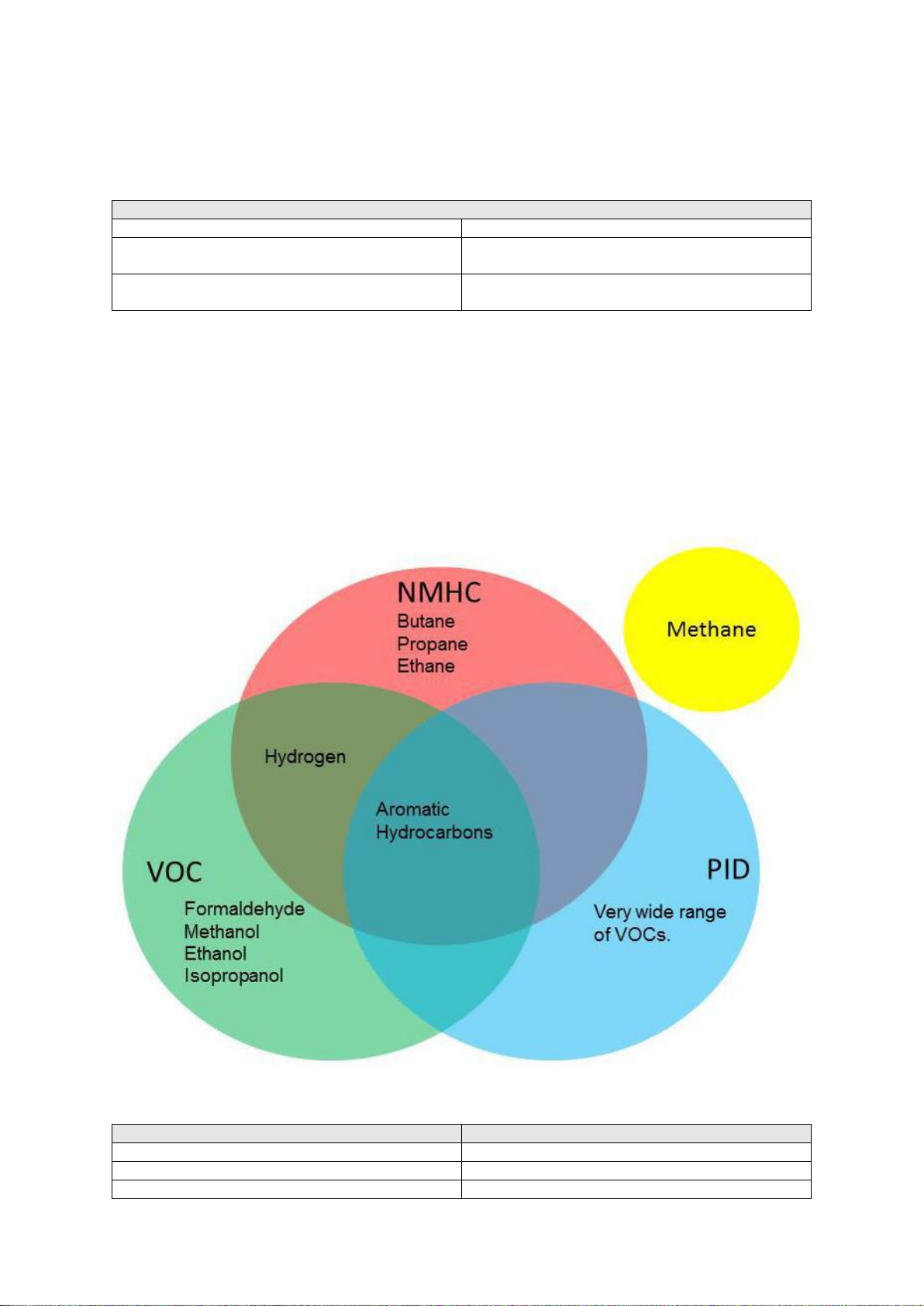
Aeroqual VOC (Volatile Organic Carbon) sensors
PID (10.6 eV)
Photoionization Detector 10.6 electron Volts.
GSS VOC
Gas Sensitive Semiconductor Volatile Organic
Carbon
GSS NMHC
Gas Sensitive Semiconductor Non Methane
Hydrocarbon
Sensor
Products
PID
AQM 65, Portable Series, 900 Series
GSS VOC
Portable Series, 900 Series
GSS NMHC
AQM 65, Portable Series, 900 Series
13.7 Volatile Organic Compound (VOC) sensors
Aeroqual offers three different types of sensor for measurement of volatile organic compounds
(VOCs): PID, GSS VOC and GSS NMHC.
These sensors have been designed to respond to a broad range of VOCs although they each display
a unique sensitivity to certain VOCs or classes of hydrocarbon, see diagram above.
The three sensors are all sensitive towards aromatic hydrocarbons.
None of the sensors respond to methane.
The NMHC sensor, and VOC sensor show unique sensitivity towards certain organic
compounds as shown below.
These differences and similarities in selectivity of the different compounds should be considered when
choosing a sensor for a particular application.
The Aeroqual products which support the different types of VOC sensor are shown in the table below.
MRK-D-0022 V4 Aeroqual Series 200, 300 & 500 User Guide Page | 49
Page 50

Gas Sensor
Code
Sensor
Range
(ppm)
Minimum
Detection
Limit
(ppm)
Accuracy of
Calibration
Resolution
(ppm)
Operational Range
Temp.
RH
Methane (CH4)
MT
GSS
0-
10000
10
<±20 ppm
+15%
1
0 to 40°C
10 to 90%
Formaldehyde
(CH20)
EF
GSE
0-10
0.01
<±0.05 ppm
@ 0-0.5 ppm
<± 10% @
0.5-10 ppm
0.1
0 to 40°C
10 to 90%
Perchloroethylene
(C2Cl4)
PE
GSS
0 -
200
1
<±5 ppm @ 0-
50 ppm
<± 10% @
50-200 ppm
1
0 to 40°C
10 to 90%
Hydrogen (H2)
HA
GSS
0-
5000
5
<±10 ppm
+10%
1
0 to 40°C
10 to 90%
Gas Sensor
Code
Sensor
Range
(ppm)
Minimum
Detection
Limit
(ppm)
Accuracy of
Calibration
Resolution
(ppm)
Operational Range
Temp.
RH
VOC
PDL
PID
0-20
0.01
<±10%
0.01
0 to 40°C
10 to 90%
VOC
PDH
PID
0-1000
0.2
<±10%
0.1
0 to 40°C
10 to 90%
Calibration, and correction factors for Aeroqual VOC sensors:
All VOC sensors are calibrated at the Aeroqual factory using isobutylene. This means in the
presence of 1 ppm isobutylene all three sensors will report 1 ppm.
The isobutylene conversion factor from ppm to mg/m3: 1 ppm = 2.29 mg/m3
However in the presence of other volatile organic compounds the response will very different for each
sensor type. Correction factors for a range of different gases for the PID sensor are listed below.
NOTE: If the GSS VOC or GSS NMHC sensor is being used to measure another organic compound
Aeroqual advises to calibrate the VOC sensor towards that compound using a gas standard
comprised of that compound.
Other related compounds can be measured using Aeroqual’s specific sensors.
NOTE: If the atmosphere being measured contains a mixture of hydrocarbons, which is likely the
case when measuring outdoor ambient air, then the measurement should be considered to be
qualitative only.
Aeroqual PID sensor response correction factors
The Aeroqual PID sensor response to a variety of gases is given in the table below. The Response
Factor (RF) provides a sensitivity measure relative to isobutylene (RF=1). The PID sensor is more
sensitive to compounds with lower RF values. Compounds not listed may also be detected by PID For more information contact Aeroqual.
VOC (PID) Sensor Specifications
MRK-D-0022 V4 Aeroqual Series 200, 300 & 500 User Guide Page | 50
Page 51

Compound
Response Factor (RF)
(a smaller RF means the PID is more sensitive
to the compound)
1,2,3-trimethylbenzene
0.49
1,2,4-trimethylbenzene
0.43
1,2-dibromoethane
11.7
1,2-dichlorobenzene
0.50
1,3,5-trimethylbenzene
0.34
1,4-dioxane
1.4
1-butanol
3.4
1-methoxy-2-propanol
1.4
1-propanol
5.7
2-butoxyethanol
1.3
2-methoxyethanol
2.5
2-pentanone
0.78
2-picoline
0.57
3-picoline
0.90
4-hydroxy-4-methyl-2-pentanone
0.55
acetaldehyde
10.8
acetic acid
11.0
acetone
1.2
acetophenone
0.59
acrolein
3.9
allyl alcohol
2.5
ammonia
9.4
amylacetate
3.5
arsine
2.6
benzene
0.53
bromoform
2.3
bromomethane
1.8
butadiene
0.69
butyl acetate
2.4
carbon disulfide
1.2
chlorobenzene
0.4
cumene (isopropylbenzene)
0.54
cyclohexane
1.5
cyclohexanone
0.82
decane
1.6
diethylamine
1.0
Response Factors (RF)
The default sensor concentration reading is in units of ppm of Isobutylene. The user can convert this
into ppm of another gas by multiplying the reading by the response factor (RF) listed in the table
below.
Response factor example
The PID sensor head is calibrated against Isobutylene and is being used to measure the
concentration of heptane.
The reading in ppm of Isobutylene is 10ppm.
Therefore the concentration of heptane is 10 ppm x 2.5 = 25 ppm.
The VOC sensor can also be used to qualitatively indicate the total VOC level. The units of
measurement are ppm Isobutylene equivalent.
This following list of PID correction factors is a shortened list reproduced from:
http://www.alphasense.com/WEB1213/wp-content/uploads/2014/06/AAN-305-05.pdf
MRK-D-0022 V4 Aeroqual Series 200, 300 & 500 User Guide Page | 51
Page 52

Compound
Response Factor (RF)
(a smaller RF means the PID is more sensitive
to the compound)
dimethoxymethane
11.3
dimethyl disulfide
0.3
diesel fuel #1
0.9
diesel fuel #2
0.75
epichlorhydrin
7.6
ethanol
10.0
ethyl acetate
4.2
ethyl acetoacetate
0.9
ethyl acrylate
2.3
diethyl ether
1.2
ethyl mercaptan
0.6
ethylbenzene
0.51
ethylene
10.1
gasoline
1.1
heptane
2.5
hydrazine
2.6
hydrogen sulfide
3.2
isoamyl acetate
1.8
isobutanol
4.7
isobutyl acetate
2.6
isobutylene
1.0
isooctane
1.3
isopentane
8.0
isophorone
0.74
isoprene (2-methyl-1,3-butadiene)
0.6
isopropanol
5.6
isopropyl acetate
2.6
isopropyl ether
0.8
isopropylamine
0.90
Jet A Fuel
0.4
JP-5 Fuel
0.48
JP-8 Fuel
0.48
mesityl oxide
0.47
methyl acetate
7
methyl acetoacetate
1.1
methyl acrylate
3.4
methyl benzoate
0.93
methyl ethyl ketone
0.9
methyl isobutyl ketone
1.1
ketone
1.1
methyl mercaptan
0.6
methyl methacrylate
1.5
methyl tert-butyl ether
0.86
ether
0.86
methylamine
1.2
methylbenzil alcohol
0.8
m-xylene
0.53
naphtalene
0.37
n,n-dimethylacetamide
0.73
n,n-dimethylformamide
0.80
n-hexane
4.5
nitric oxide
7.2
n-nonane
1.6
n-pentane
9.7
n-propyl acetate
3.1
MRK-D-0022 V4 Aeroqual Series 200, 300 & 500 User Guide Page | 52
Page 53
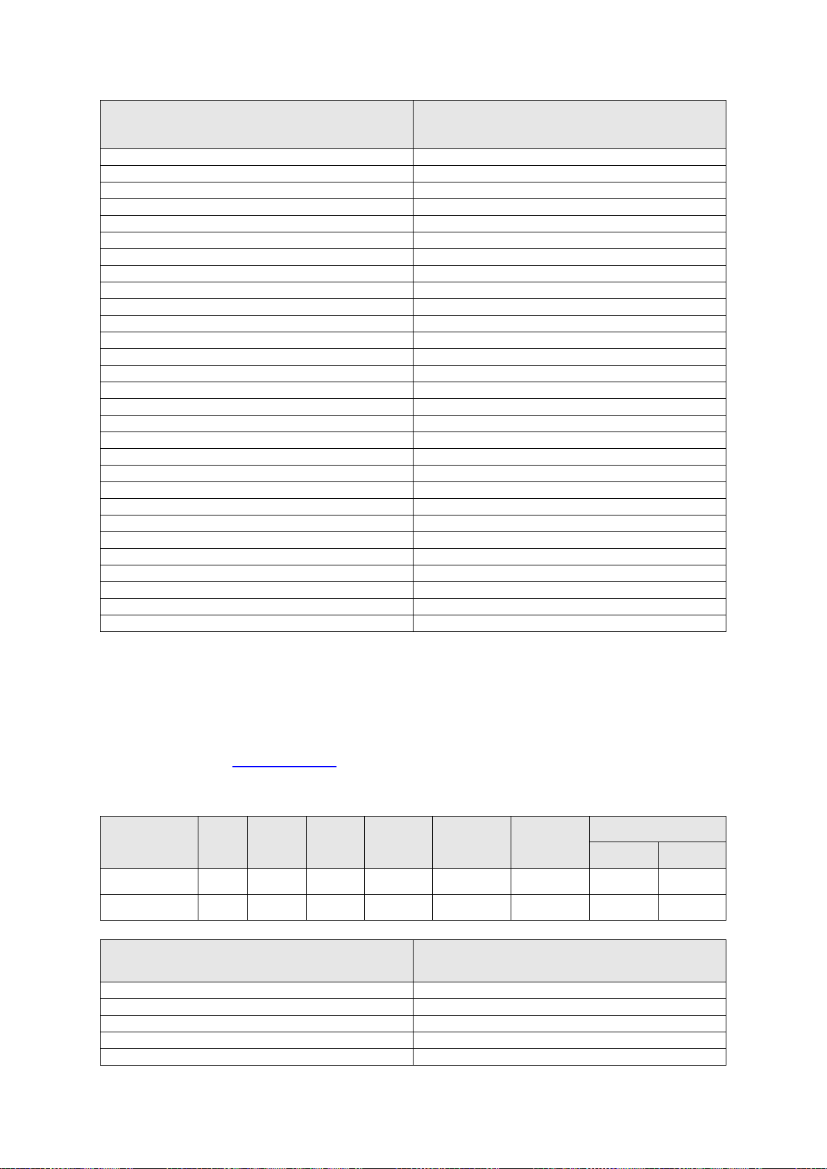
Compound
Response Factor (RF)
(a smaller RF means the PID is more sensitive
to the compound)
octane
2.2
o-xylene
0.54
phenol
1.0
phosphine
2.8
pinene, alpha
0.4
pinene, beta
0.4
propylene
1.3
propylene oxide
6.5
p-xylene
0.50
pyridine
0.79
quinoline
0.72
styrene
0.40
tert-butyl alcohol
3.4
tert-butyl mercaptan
0.55
tert-butylamine
0.71
tetrachloroethylene
0.56
tetrahydrofuran
1.6
thiophene
0.47
toluene
0.53
trans-1,2-Dichloroethene
0.45
trichloroethylene
0.50
trimethylamine
0.83
turpentine crude sulfite
1.0
turpentine pure gum
0.45
vinyl acetate
1.3
vinyl bromide
0.4
vinyl chloride
1.8
vinylcyclohexane (VCH)
0.54
vinylidene chloride (1,1-DCE)
0.8
Gas Sensor
Code
Sensor
Range
(ppm)
Minimum
Detection
Limit
(ppm)
Accuracy of
Calibration
Resolution
(ppm)
Operational Range
Temp.
RH
VOC
VM
GSS
0-25
0.1
<±0.1 ppm +
10 %
0.01
0 to 40°C
10 to 90%
VOC
VP
GSS
0-500
1
<± 5ppm +
10 %
0.1
0 to 40°C
10 to 90%
Compound
Response Factor (RF)
(a smaller RF means the GSS is more sensitive to the
compound)
CO
10
propane
80
toluene
1
butane
20
ethanol
0.15
Aeroqual GSS sensor response correction factors
The Aeroqual GSS sensor response to a selection of gases is given in the table below. The Response
Factor (RF) provides a sensitivity measure relative to isobutylene (RF=1). The GSS sensor is more
sensitive to compounds with lower RF values. Compounds not listed may also be detected by GSS For more information contact Aeroqual.
VOC (GSS) Sensor Specifications
MRK-D-0022 V4 Aeroqual Series 200, 300 & 500 User Guide Page | 53
Page 54

Compound
Response Factor (RF)
(a smaller RF means the GSS is more sensitive to the
compound)
ethyl acetate
0.2
isopropanol (IPA)
0.07
SO2
0.2
H2S
0.02
heptane
3
hydrogen
10
dodecane
2.5
MRK-D-0022 V4 Aeroqual Series 200, 300 & 500 User Guide Page | 54
Page 55

14 Copyright
Copyright Aeroqual Limited. All rights reserved. Reproduction, transfer, distribution or storage of part
or all of the contents of this document in any form without the prior written permission of Aeroqual
Limited is prohibited.
“Aeroqual” and “Aeroqual Limited – Making the Invisible Visible” are registered trademarks of
Aeroqual Limited. Other product and company names mentioned herein may also be trademarks or
trade names.
Aeroqual operates a policy of continuous development. Aeroqual re-serves the right to make changes
and improvements to any of the products described in this document without prior notice.
Under no circumstances shall Aeroqual be responsible for any loss of data or income or any special,
incidental, consequential or indirect damages howsoever caused.
The contents of this document are provided "as is". Except as required by applicable law, no
warranties of any kind, either express or implied, including, but not limited to, the implied warranties of
merchantability and fitness for a particular purpose, are made in relation to the accuracy, reliability or
contents of this document.
Aeroqual reserves the right to revise this document or withdraw it at any time without prior notice. The
availability of particular products may vary by region. Please check with the Aeroqual dealer nearest
to you.
15 Software License
The Series 500 monitor comes supplied with Aeroqual data logging software. Aeroqual will retain
ownership of all intellectual property in the Software. The buyer acknowledges that they are granted a
perpetual, non-exclusive, non-transferable license for the right to use the Software for the buyer’s
exclusive use and only in conjunction with Aeroqual Products (Intended use). The buyer will strictly
adhere to the Intended Use of the Software and will not translate, adapt, reverse compile or otherwise alter the Software. The buyer undertakes not to disclose, assign, sell, rent, lend, sub license or
otherwise transfer the Software.
16 Terms and Conditions
This product is warranted according to Aeroqual Ltd’s Terms of Trade. For further warranty
information, please refer to the standard Product Warranty Policy as published on the Aeroqual
website at www.aeroqual.com.
MRK-D-0022 V4 Aeroqual Series 200, 300 & 500 User Guide Page | 55
Page 56
17 Statements of Compliance
The Aeroqual Series 200, 300 and 500 Monitors and Remote Adaptor Kit comply with EN
50082-1:1997
The Aeroqual Series 200, 300 and 500 Monitors and Remote Adaptor Kit comply with EN
50081-1:1992
The Aeroqual Series 200, 300 and 500 Monitors and Remote Adaptor Kit comply with Part
15 of the FCC Rules. Operation is subject to the following two conditions: (1) these devices
may not cause harmful interference, and (2) these devices must accept any interference
received, including interference that may cause undesired operation.
NOTE: This equipment has been tested and found to comply with the limits for a Class B digital device,
pursuant to Part 15 of the FCC Rules. These limits are designed to provide reasonable protection
against harmful interference in a residential installation. This equipment generates, uses and can
radiate radio frequency energy and, if not installed and used in accordance with the instructions, may
cause harmful interference to radio communications. However, there is no guarantee that interference
will not occur in a particular installation. If this equipment does cause harmful interference to radio or
television reception, which can be determined by turning the equipment off and on, the user is
encouraged to try to correct the interference by one or more of the following measures:
Reorient or relocate the receiving antenna.
Increase the separation between the equipment and receiver.
Connect the equipment into an outlet on a circuit different from that to which the receiver is
connected.
Consult the dealer or an experienced radio/TV technician for help.
MRK-D-0022 V4 Aeroqual Series 200, 300 & 500 User Guide Page | 56
 Loading...