

Aero Pure AP70-S Installation Manual
BATHROOM FAN
MODEL: AP70-S
WARNING
TO REDUCE THE RISK OF FIRE, ELECTRIC SHOCK, OR INJURY TO PERSONS, PLEASE READ THE FOLLOWING:
CAUTION
1. For general ventilating use only. Do not use to exhaust hazardous or explosive materials and vapors. 2. This product is designed
for installation in ceilings up to a 12/12 pitch (45 degree angle). DO NOT MOUNT THIS PRODUCT IN A WALL. 3. To avoid motor
bearing damage and noisy and/or unbalanced impellers, keep drywall spray, construction dust, etc. off power unit. 4. Please read
specification label on product for further information and requirements.
*This manual in electronic format may be downloaded from our company website or obtained from the dealer.
CLEANING & MAINTENANCE
For quiet and efficient operation, long life, and attractive appearance, lower or remove grille and vacuum interior of unit with the
dusting brush attachment.
The motor is permanently lubricated and never needs oiling.
OPERATION
Use an on/off switch to operate this fan. See “Connect Wiring” for details.
ASSEMBLY INSTRUCTIONS
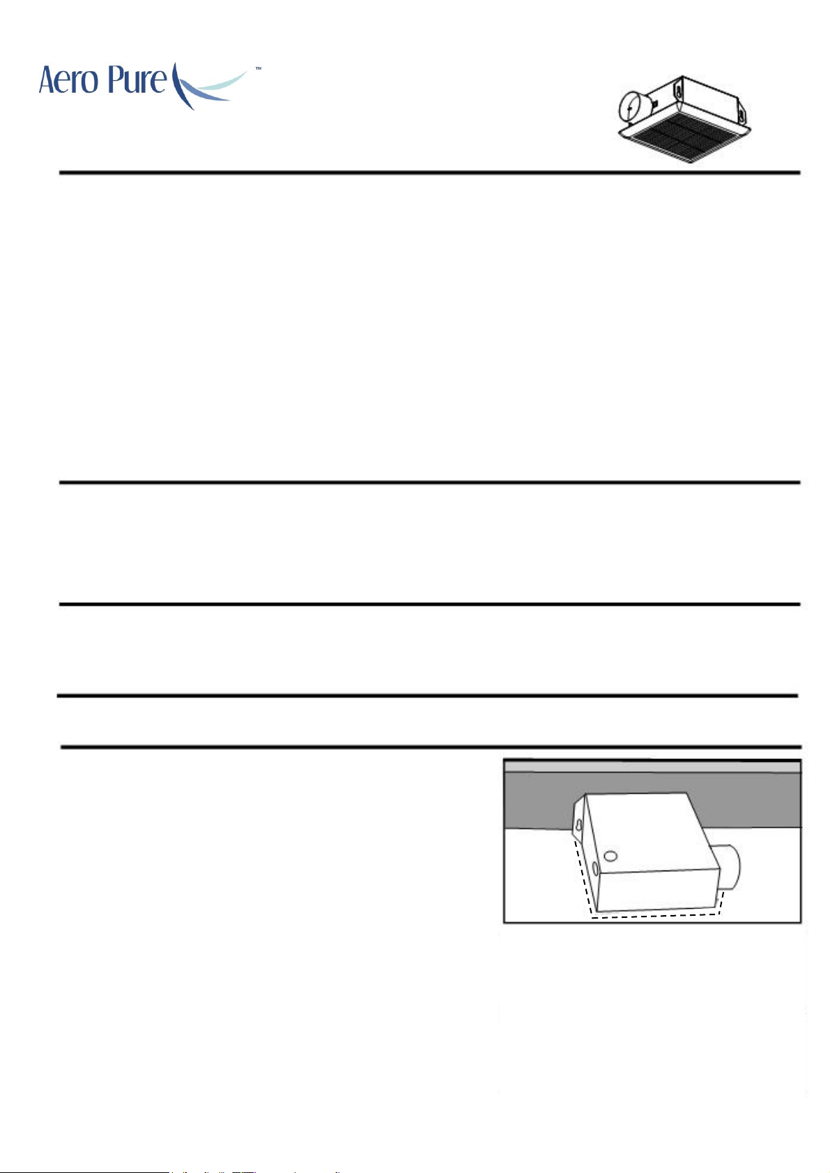
MOUNT DIRECTLY TO JOIST OR I-JOIST
Place the housing assembly in the opening so the bottom edge is flush
with the finished ceiling. Nail the housing assembly to the joist using nails.
POSITION THE HOUSING ASSEMBLY
Position the housing assembly against the joist. With a pencil, trace an
outline of the housing assembly onto the ceiling. Set the housing aside,
and cut out an opening for the fan. DO NOT MOUNT THIS PROUCT IN A
WALL.
Prohibition
Prohibition
Prohibition
READ AND SAVE THESE INSTRUCTIONS
Installer: Leave this manual with the homeowner.
www.aeropurefans.com
1.Use this unit only in the manner intended by the manufacturer. If you have questions, contact the manufacturer at the address
or telephone number listed in the warranty. 2.Before servicing or cleaning unit, switch power off at service panel and lock the
service disconnecting means to prevent power from being switching on accidentally. If the service disconnecting means cannot
be locked, securely fasten a prominent warning device, such as a tag, to the service panel. 3. Installation work and electrical
wiring must be done by a licensed person(s) in accordance with all applicable codes and standards, including fire-rated
construction codes and standards. 4. Sufficient air is needed for proper combustion and exhausting of gases through the flue
(chimney) of fuel burning equipment to prevent backdraft. Follow the heating equipment manufacturer’s guideline and safety
standards such as those published by the National Fire Protection Association (NFPA), and the American Society for Heating,
Refrigeration and Air Conditioning Engineers (ASHRAE), and the local code authorities. 5. When cutting or drilling into wall or
ceiling, do not damage electrical wiring and other hidden utilities. 6. Ducted fans must always be vented to the outdoors.
7. Acceptable for use over a tub or shower when connected to a GFCI (Ground Fault Circuit Interrupter) protected branch circuit.
8. This unit must be grounded. 9. Never place a switch where it can be reached from a tub or shower. 10. Not for use in kitchens.
11. Install fan at least 2.5 m (8.2 feet) above the floor. 12. WARNING: To reduce the risk of fire or electric shock, do not use this
fan with any solid-state speed control device. 13. The fan must not be installed in a ceiling thermally insulated to a value greater
than R40.
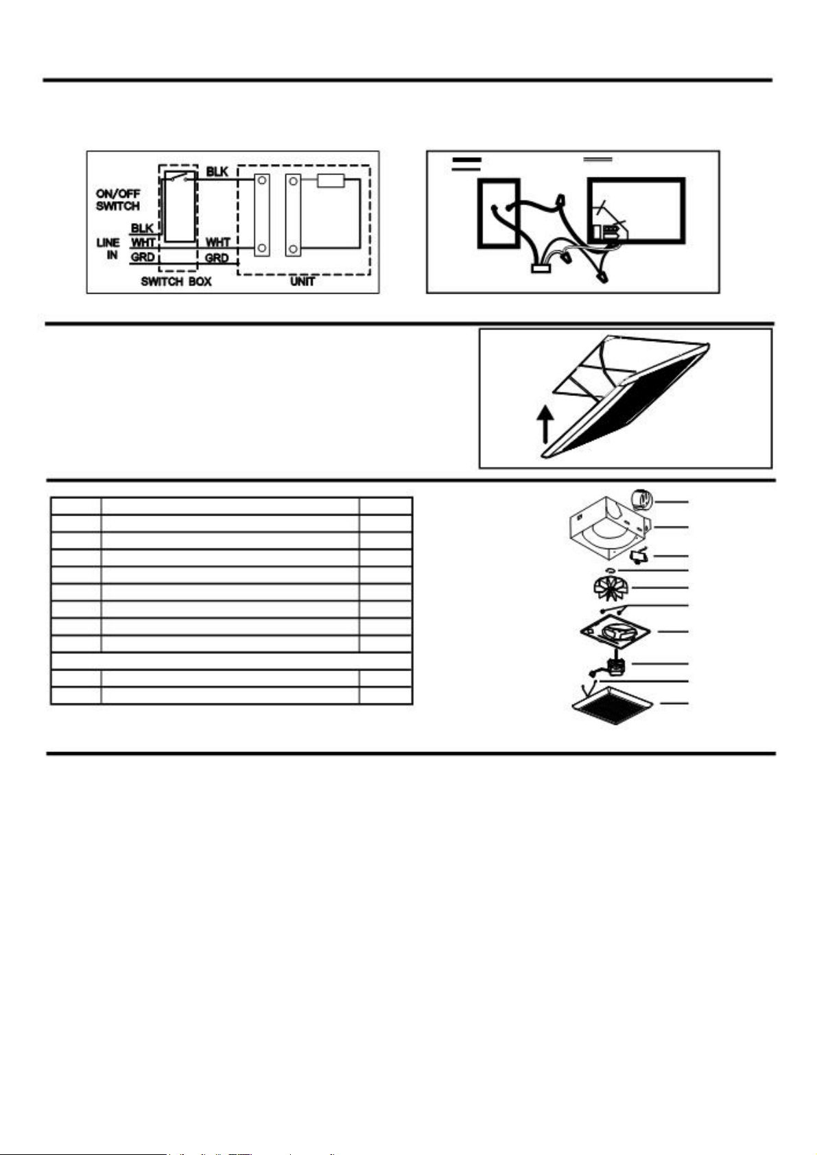
CONNECT ELECTRICAL WIRING
Lock off and test all power sources before unit is wired. All wiring should be in accordance with local ordinances and National Electrical
Code, NFPA70. Use proper UL approved connectors to secure wiring to wire plate. Ensure approved connectors to secure wiring to
wire plate. Ensure power supply (voltage, frequency, and current capacity of wiring) is in accordance with the motor nameplate.
Connect all wiring as shown in wiring diagram.
BLACK (BLK)
WHITE (WHT)
GROUND (GRD)
FAN
WIRE PANEL
UNIT
FAN
SWITCH
FAN
RECEPTACLE
SWITCH BOX
POWER SUPPLY
120V AC
INSTALL GRILLE
Press the springs on the grille together and insert springs into the motor
plate inside the housing assembly. Firmly push the grille up against the
ceiling.
SERVICE PARTS
8
PART
PART NAME
Qty.
1
Grille Assembly (includes part 2)
1
7 2 Grille Spring
2
3
Motor
1
6
b 4 Motor Plate
1
5
5
Blower Wheel
1
a
6
Wire Panel / Harness Assembly
1
7
Housing
1
4 8 Damper / Duct Connector
1
3 a Nut 2 2 b Circlip
1
1
WARRANTY
2
READ AND SAVE THESE INSTRUCTIONS
Installer: Leave this manual with the homeowner.
This warranty covers all defects in workmanship or materials for:
The mechanical and electrical parts contained in this product for a period of 72 months from the date of purchase. You must keep and be able to
provide your original sales receipt as proof of date of purchase. This warranty is covered to the original retail purchaser of this product only. The
manufacturer will replace any mechanical or electrical part that proves defective in normal household use for a period of 72 months.
THIS WARRANTY DOES NOT COVER:.
• Damages from improper installation
• Damages from shipping.
• Damages from misuse, abuse, accident, alteration, lack of proper care and maintenance.
• Damages from service by persons other than a licensed electrician.
• Does not cover any labor or transportation charges related to the repair of this product.
THIS LIMITED WARRANTY IS GIVEN IN LIEU OF ALL OTHER WARRANTIES, EXPRESSED OR IMPLIED, INCLUDING THE WARRANTIES OF
MERCHANTABILITY AND FITNESS FOR A PARTICULAR PURPOSE.
The remedy provided in this warranty is exclusive and is granted in lieu of all other remedies. This warranty does not cover incidental or
consequential damages. Some states do not allow the exclusion of incidental or consequential damages, so this limitation may not apply to you.
Some states do not allow limitations on how long an implied warranty lasts, so this limitation may not apply to you. This warranty gives you specific
legal rights; you may also have other rights that vary from state to state.
Aero Pure AP70-S
 Loading...