

Aeronix AE102882 User Manual

Data Links
User Guide – EDL Nano Product
AE301628-001
REV B
3 October 2019
For:
Part No. AE102474 & AE102882
Prepared by:
1775 West Hibiscus Blvd, Suite 200
Melbourne, FL 32901
(321) 984-1671
Aeronix Proprietary

Form #: OP_01_TM
Title: Aeronix Data Links – EDL Nano Products User Guide
Review/Approval Title
Name
Originator:
S. Baduini
Approved By:
Program Manager
L. Clarkson
Approved By:
Quality Assurance
C. Hertzberg
Approved By:
Configuration Management
D. Franks
Ver/Rev
Description of Change
Chg’d By
Chg/Rel #
Date
-001/-
Initial L1 Release to CM
LC & SB
SP-2493
7/10/2019
-001/A
Release with updates for FCC testing
LC
SP-2519
9/11/2019
-001/B
Updated with FCC Statements
LC
10/3/2019
Document Authorization
Document Revision History
Document Number: AE301628-001
Revision: B Date: 3 October 2019
Aeronix Proprietary
Page ii

Form #: OP_01_TM
Title: Aeronix Data Links – EDL Nano Products User Guide
Table of Contents
1. INTRODUCTION .............................................................................................................................................. 1
1.1.1. Purpose .................................................................................................................................................. 1
1.2. REFERENCES ............................................................................................................................................... 1
1.2.1. Government Documents ......................................................................................................................... 1
1.2.2. Non-Government Documents ................................................................................................................. 1
1.3. OVERVIEW .................................................................................................................................................. 1
1.4. NOTES FOR FCC ID ..................................................................................................................................... 1
2. EDL NANO - ENHANCED DATA LINK (AE102429) AND RUGGED ENHANCED DATA LINK
(AE102882) ................................................................................................................................................................... 3
2.1. EDL NANO FEATURES ................................................................................................................................ 3
2.2. EDL NANO INSTALLATION AND STARTUP PROCEDURES ............................................................................. 4
2.2.1. Input Power Supply ................................................................................................................................ 4
2.3. EDL NANO PHYSICAL I/O ........................................................................................................................... 6
2.3.1. USB OTG ............................................................................................................................................... 9
2.3.2. USB Host ............................................................................................................................................... 9
2.3.3. Ethernet 1 & 2 ....................................................................................................................................... 9
2.3.4. Console RS-232 ..................................................................................................................................... 9
2.3.5. Platform RS-232 .................................................................................................................................. 10
2.3.6. P1 Antenna Interface TxRx 1 ............................................................................................................... 10
2.3.7. P2 Antenna Interface Rx 2 ................................................................................................................... 10
2.3.8. Tx Rx Enable ........................................................................................................................................ 10
2.3.1. Tx Rx Enable 4 State (OFDM only) ..................................................................................................... 11
2.3.2. External GPIO 1 & 3 ........................................................................................................................... 11
2.3.3. Red and Green LED ............................................................................................................................. 11
2.3.4. Tamper ................................................................................................................................................. 11
2.3.5. RF Output Power ................................................................................................................................. 11
3. SYSTEM CONFIGURATION........................................................................................................................ 11
3.1. AERONIX GUI INTERFACE ......................................................................................................................... 11
3.2. SNMP INTERFACE ..................................................................................................................................... 12
3.3. STARTUP ................................................................................................................................................... 12
3.4. RADIO MAINTENANCE LOGIN ................................................................................................................... 12
3.4.1. Using Serial Port A .............................................................................................................................. 12
3.5. ETHERNET ALIAS IP ADDRESS ................................................................................................................... 12
3.6. WEB BASED GUI SYSTEM CONFIGURATION ............................................................................................ 12
3.6.1. Base Station Status Page ..................................................................................................................... 13
3.6.2. Base Station Admin Page ..................................................................................................................... 17
3.6.3. Base Station Network Configuration Page .......................................................................................... 26
3.6.4. Base Station Profile Config Page ........................................................................................................ 45
3.6.5. Base Station Radio Control ................................................................................................................. 50
3.6.6. Base Station Maintenance Page .......................................................................................................... 54
3.6.7. Base Station Video Page ...................................................................................................................... 59
3.6.8. Subscriber Station Status ..................................................................................................................... 61
3.6.9. Subscriber Station Admin Page ........................................................................................................... 63
3.6.10. Subscriber Network Config Page .................................................................................................... 67
3.6.11. Subscriber Profile Config Page ...................................................................................................... 69
3.6.12. Subscriber Station Radio Control Page .......................................................................................... 70
3.6.13. Subscriber Station Maintenance Page ............................................................................................ 74
3.6.14. Subscriber Station Video Page ........................................................................................................ 77
3.6.15. BS and SS Common Pages .............................................................................................................. 80
3.7. SNMP INTERFACE CONFIGURATION .......................................................................................................... 90
Document Number: AE301628-001
Revision: B Date: 3 October 2019
Aeronix Proprietary
Page iii

Form #: OP_01_TM
Title: Aeronix Data Links – EDL Nano Products User Guide
3.7.1. SNMP User Authentication .................................................................................................................. 91
3.7.2. SNMP examples ................................................................................................................................... 91
3.7.3. SNMP Unsupported configurations ................................................................................................... 106
4. DETERMINING NANO RADIO CONFIGURATION .............................................................................. 106
4.1. TWO WAYS TO DETERMINE RADIO IP ADDRESS ....................................................................................... 106
4.1.1. Use Console ....................................................................................................................................... 106
4.1.2. Use radio’s default IP address .......................................................................................................... 107
5. CHANGE RADIO IP ADDRESS VIA WEBGUI ........................................................................................ 107
6. ADDING SUBSCRIBER EXAMPLE USING WEBGUI ........................................................................... 108
6.1. CONFIGURING MULTIPLE SERVICE FLOWS .............................................................................................. 112
7. AERONIX SOFTWARE FEATURES ......................................................................................................... 117
7.1. NANO OUTPUT POWER ........................................................................................................................... 117
7.1.1. View NANO output power calibration ............................................................................................... 117
7.2. ARP TABLE FEATURE .............................................................................................................................. 122
7.2.1. Enable Aeronix ARP feature .............................................................................................................. 122
7.3. AERONIX SERIAL FLOW CONTROL FEATURE ........................................................................................... 123
8. RADIO PERFORMANCE ............................................................................................................................ 125
8.1. GMSK NANO RF INTERFERENCE PERFORMANCE ................................................................................. 125
8.2. NANO GMSK RECEIVER SENSITIVITY ................................................................................................... 125
8.3. OFDM NANO RF INTERFERENCE PERFORMANCE ................................................................................. 125
8.4. NANO OFDM RECEIVER SENSITIVITY ................................................................................................... 125
8.5. DATA RATES ........................................................................................................................................... 126
8.5.1. OFDM Max Data Rates ..................................................................................................................... 126
8.5.2. GMSK Data Rates .............................................................................................................................. 127
9. MECHANICALS ........................................................................................................................................... 129
9.1. PART NUMBER AE102429 ...................................................................................................................... 130
APPENDIX A: SNMP MIB .................................................................................................................................... 131
APPENDIX C: DEFINITIONS, ACRONYMS, AND ABBREVIATIONS ........................................................ 182
Document Number: AE301628-001
Revision: B Date: 3 October 2019
Aeronix Proprietary
Page iv

Form #: OP_01_TM
Title: Aeronix Data Links – EDL Nano Products User Guide
Table of Figures
Figure 2-1 NANO .................................................................................................................................. 3
Figure 2-2 NANO RF Input/Output ....................................................................................................... 6
Figure 2-3 Nano Physical I/O ................................................................................................................ 7
Figure 2-4 TR SW Timing ................................................................................................................... 10
Figure 3-1 BS GMSK Status ................................................................................................................ 14
Figure 3-2 BS Status GMSK RX Dual mode ...................................................................................... 16
Figure 3-3 BS Admin Page .................................................................................................................. 17
Figure 3-4 BS Admin Station Names .................................................................................................. 18
Figure 3-5 BS Admin Transec Key Mgmt ........................................................................................... 19
Figure 3-6 BS Bridging Script and S/W Update .................................................................................. 20
Figure 3-7 Example Adding a SS entry ............................................................................................... 22
Figure 3-8 Example Modify Transec Key ........................................................................................... 22
Figure 3-9 Example Modify Transec Key Result ................................................................................ 22
Figure 3-10 Example Generate Start Script ......................................................................................... 23
Figure 3-11 Example Software Update ................................................................................................ 24
Figure 3-12 Example Software Update Progress ................................................................................. 25
Figure 3-13 Software Update Result .................................................................................................... 25
Figure 3-14 BS Network Config .......................................................................................................... 26
Figure 3-15 BS Network Config Network Options ............................................................................. 26
Figure 3-16 BS Network Config Service Classes ................................................................................ 27
Figure 3-17 BS Example Add Service Class ....................................................................................... 29
Figure 3-18 BS Example Modify Service Class .................................................................................. 30
Figure 3-19 BS Provisioned SFs .......................................................................................................... 30
Figure 3-20 BS Example Add Provisioned SFs ................................................................................... 32
Figure 3-21 BS Example Modify Service Flow................................................................................... 32
Figure 3-22 BS Network Config Class Rules ...................................................................................... 33
Figure 3-23 BS Network Config Auto Populate .................................................................................. 35
Figure 3-24 Example Auto Populate Network Layout ........................................................................ 36
Figure 3-25 BS Example Auto Populate .............................................................................................. 37
Figure 3-26 BS Example Auto Populate Result................................................................................... 37
Figure 3-27 BS Example Auto Populate Additional Class Rules ........................................................ 38
Figure 3-28 BS Example Additional Class Rules Result ..................................................................... 39
Figure 3-29 BS Example Auto Populate IP with Forwarders .............................................................. 40
Figure 3-30 BS Example Auto Populate IP with Forwarders Result ................................................... 40
Figure 3-31 BS Example Auto Populate with MAC Address ............................................................. 41
Figure 3-32 BS Example Auto Populate with MAC Address Result .................................................. 42
Figure 3-33 BS Example Class Rules ADD ENTRY .......................................................................... 43
Figure 3-34 BS Example MODIFY ENTRY selection ....................................................................... 44
Figure 3-35 BS Example MODIFY ENTRY ....................................................................................... 44
Figure 3-36 OFDM BS Profile Config Page ........................................................................................ 45
Figure 3-37 GMSK BS Profile Config Page ........................................................................................ 46
Figure 3-38 BS 802.16 Example Add Burst Profile ............................................................................ 48
Figure 3-39 BS 802.16 Example Modify Burst Profile ....................................................................... 49
Figure 3-40 OFDM BS Radio Control Page ........................................................................................ 50
Figure 3-41 GMSK BS Radio Control ................................................................................................. 51
Document Number: AE301628-001
Revision: B Date: 3 October 2019
Aeronix Proprietary
Page v

Form #: OP_01_TM
Title: Aeronix Data Links – EDL Nano Products User Guide
Figure 3-42 BS GMSK Maintenance Page .......................................................................................... 55
Figure 3-43 BS Maintenance Registered SS Page ............................................................................... 58
Figure 3-44 BS Video Page ................................................................................................................. 59
Figure 3-45 SS OFDM Status Page ..................................................................................................... 61
Figure 3-46 SS OFDM Status Rx Dual ................................................................................................ 63
Figure 3-47 SS Admin Page................................................................................................................. 64
Figure 3-48 SS Admin Station Name and Transec Key ...................................................................... 64
Figure 3-49 SS Admin Start Script and SW Update ............................................................................ 66
Figure 3-50 SS Network Config Page.................................................................................................. 68
Figure 3-51 SS OFDM Profile Config Page ........................................................................................ 69
Figure 3-52 SS OFDM Radio Control Page ........................................................................................ 71
Figure 3-53 SS GMSK Radio Control ................................................................................................. 72
Figure 3-54 SS OFDM Maintenance Page .......................................................................................... 74
Figure 3-55 SS Video Page .................................................................................................................. 78
Figure 3-56 Save Settings Selection .................................................................................................... 81
Figure 3-57 Version Page .................................................................................................................... 82
Figure 3-58 Maintenance Reboot Selection ......................................................................................... 83
Figure 3-59 Maintenance Use Default DB Selection ........................................................................... 84
Figure 3-60 OFDM Maintenance System Tests Page .......................................................................... 85
Figure 3-61 Maintenance Debug Page ................................................................................................. 88
Figure 6-1 Example Adding Subscriber Layout ................................................................................ 108
Figure 6-2 Example Adding a Subscriber station name .................................................................... 109
Figure 6-3 Example Adding a Subscriber Provisioned SF ................................................................ 109
Figure 6-4 Example Adding a Subscriber Class Rules ...................................................................... 111
Figure 6-5 Example Adding a Subscriber Result ............................................................................... 112
Figure 6-6 Example Multiple SF Layout ........................................................................................... 113
Figure 6-7 Example Multiple SF Add SF .......................................................................................... 113
Figure 6-8 Example Multiple SF Add Class Rules ............................................................................ 114
Figure 6-9 Example Multiple SF Result ............................................................................................ 116
Figure 6-10 Example Multiple SF BS Status Page ............................................................................ 117
Figure 6-11 SS Example Multiple SF SS Status Page ....................................................................... 117
Figure 7-1 802.16 phyEeprom interface ............................................................................................ 120
Figure 7-2 OFDM phyEeprom interace ............................................................................................. 120
Figure 7-3 GMSK powerSettings interface ....................................................................................... 121
Figure 7-4 Serial B to Serial B Exp ................................................................................................... 124
Figure 7-5 BS serial config exp ......................................................................................................... 124
Figure 7-6 SS serial config exp .......................................................................................................... 125
Document Number: AE301628-001
Revision: B Date: 3 October 2019
Aeronix Proprietary
Page vi

Form #: OP_01_TM
Title: Aeronix Data Links – EDL Nano Products User Guide
Table of Tables
Table 2-1. GMSK Typical Peak Current and Power 1800 Mhz ............................................................ 4
Table 2-2. GMSK Typical Peak Current and Power 2300 MHz ........................................................... 4
Table 2-3. OFDM Typical Current and Power 1800 MHz .................................................................... 4
Table 2-4. OFDM Typical Current and Power 2300 MHz .................................................................... 5
Table 2-5. OFDM Typical Current and Power 2427 MHz .................................................................... 5
Table 2-6. Nano Hardware Interface...................................................................................................... 6
Table 2-7. Nano Hardware Interface...................................................................................................... 7
Table 2-8. J1: Main IF Pin Definitions ................................................................................................. 7
Table 2-9. J2: Camera IF Pin Definitions .............................................................................................. 9
Table 2-10 GMSK 14 MHz T/R SW Timing ...................................................................................... 10
Table 2-11 OFDM T/R SW Timing ..................................................................................................... 11
Table 3-1. Base Station Status Page .................................................................................................... 14
Table 3-2. Base Station Status Page RX Dual Mode ........................................................................... 16
Table 3-3. BS Admin Page Station Names .......................................................................................... 18
Table 3-4. BS Admin Transec Key Mgmt ........................................................................................... 19
Table 3-5. BS Admin Start Script and S/W Update ............................................................................. 20
Table 3-6. Base Station Network Config Network Options ................................................................ 27
Table 3-7. Base Station Network Config Service Class ...................................................................... 28
Table 3-8. Base Station Network Config Service Class ...................................................................... 30
Table 3-9. Base Station Network Config Service Class ...................................................................... 33
Table 3-10. Base Station Network Config Auto Populate ................................................................... 35
Table 3-11. Base Station Profile Config Page ..................................................................................... 46
Table 3-12. Base Station Radio Control .............................................................................................. 51
Table 3-13. Base Station Maintenance Page ....................................................................................... 55
Table 3-14. Base Station Video Page................................................................................................... 59
Table 3-15. Subscriber Station Status Page ......................................................................................... 62
Table 3-16. Subscriber Station Admin Page Transec Key ................................................................... 65
Table 3-17. Subscriber Station Admin Page Transec Key ................................................................... 66
Table 3-18. Subscriber Station Network Config .................................................................................. 68
Table 3-19. Subscriber Profile Config Page ....................................................................................... 69
Table 3-20. Subscriber Station Radio Control ..................................................................................... 72
Table 3-21. Subscriber Station Maintenance Page ............................................................................. 75
Table 3-22. Subscriber Station Video Page ......................................................................................... 78
Table 3-23. Version Page ..................................................................................................................... 82
Table 3-24. Maintenance System Tests Page....................................................................................... 85
Table 3-25. Maintenance Debug Page ................................................................................................. 88
Table 6-1. Adding Multiple Service Flow Class Rule ....................................................................... 114
Table 7-1. Transmit Calibration interface .......................................................................................... 122
Table 8-1. GMSK Receiver SNR Assumptions ................................................................................. 125
Table 8-2 OFDM. 14MHz Receiver SNR Assumptions .................................................................... 126
Table 8-3 OFDM. 7MHz Receiver SNR Assumptions ...................................................................... 126
Table 8-4 OFDM. 3.5 MHz Receiver SNR Assumptions .................................................................. 126
Table 8-5. 3.5 MHz BW Max Data Rates .......................................................................................... 127
Table 8-6. 7 MHz BW Max Data Rates ............................................................................................. 127
Table 8-7. 14 MHz BW Max Data Rates ........................................................................................... 127
Document Number: AE301628-001
Revision: B Date: 3 October 2019
Aeronix Proprietary
Page vii

Form #: OP_01_TM
Title: Aeronix Data Links – EDL Nano Products User Guide
Table 8-8. 14 MHz BW GMSK Max Data Rates .............................................................................. 128
Document Number: AE301628-001
Revision: B Date: 3 October 2019
Aeronix Proprietary
Page ii

Form #: OP_01_TM
Title: Aeronix Data Links – EDL Nano Products User Guide
1. Introduction
1.1.1. Purpose
User guide for Aeronix EDL Nano based family of data links. This user guide has information
based on the NANO GMSK and OFDM software release.
1.2. References
The following documents are referenced in or were used in the preparation of this document:
1.2.1. Government Documents
None.
1.2.2. Non-Government Documents
[1] “IEEE STD 802 2004 Part 16d: Air Interface for Fixed Broadband Wireless Access Systems”
Revision 2004. June 24,2004
[2] “IEEE STD 802 2005 Part16e: Air Interface for Fixed and Mobile Broadband Wireless Access
System Amendment for Physical and Medium Access Control Layers for Combined Fixed and
Mobile Operation in Licensed Bands” Revision 2005.
[3] AE301432-001 : Report RF Statistics Via Ethernet Interface Description
1.3. Overview
This user guide provides information deemed necessary to bring up the following radio products
from point of delivery:
Part No. AE102429 – EDL Nano Digital Data Link
Part No. AE102882 – EDL Nano Digital Data Link Rugged
(WARNING: DO NOT POWER UP WITHOUT A LOAD ON THE ANTENNA PORT)
1.4. Notes for FCC ID
FCC testing was completed using GMSK low power mode (30 dBm) and frequencies within the
ISM Band (2400 – 2483.4 MHz).
Exposure Statement:
RF Exposure WARNING: This equipment complies with FCC radiation exposure limits set
forth for an uncontrolled environment. This equipment should be installed and operated with
minimum distance 20 cm between the radiator and your body.
Document Number: AE301628-001
Revision: B Date: 3 October 2019
Aeronix Proprietary
1

Form #: OP_01_TM
Title: Aeronix Data Links – EDL Nano Products User Guide
FCC Part 15.19 Warning Statement- (Required for all Part 15
devices)
THIS DEVICE COMPLIES WITH PART 15 OF THE FCC RULES.
OPERATION IS SUBJECT TO THE FOLLOWING TWO
CONDITIONS: (1) THIS DEVICE MAY NOT CAUSE HARMFUL
INTERFERENCE, AND (2) THIS DEVICE MUST ACCEPT ANY
INTERFERENCE RECEIVED, INCLUDING INTERFERENCE THAT
MAY CAUSE UNDESIRED OPERATION.
FCC Part 15.21 Warning Statement-
NOTE: THE GRANTEE IS NOT RESPONSIBLE FOR ANY
CHANGES OR MODIFICATIONS NOT EXPRESSLY APPROVED
BY THE PARTY RESPONSIBLE FOR COMPLIANCE. SUCH
MODIFICATIONS COULD VOID THE USER’S AUTHORITY TO
OPERATE THE EQUIPMENT.
At 1000 mW Power (1W) and Antenna Gain of 4 (6 dB), and a minimum distance of 20cm (min
separation distance for “Mobile Devices”).
S = 0.8 mW/cm2, which is less than the Uncontrolled Exposure Maximum Permissible
Exposure (MPE) limit.
For radios labeled with FCC ID T2KAE102882 the following applies:
Document Number: AE301628-001
Revision: B Date: 3 October 2019
Aeronix Proprietary
2

Form #: OP_01_TM
Title: Aeronix Data Links – EDL Nano Products User Guide
2. EDL Nano - Enhanced Data Link (AE102429) and Rugged Enhanced Data Link
(AE102882)
This unit is a software reprogrammable data link. This unit supports both Aeronix LAW
functionality, GMSK waveform and video compression capabilities. The EDL Nano operates
over the frequency band of 1.8 to 2.5 GHz with the appropriate antenna systems. (WARNING:
DO NOT POWER UP WITHOUT A LOAD ON THE ANTENNA PORT).
Note: The pictures in this section are from AE102429. But, AE102882 operates the same and is
just in a different housing.
Figure 2-1 NANO
2.1. EDL Nano Features
Software Reprogrammable Radio
Simple yet powerful GUI for radio configuration.
Option to use SNMP for radio configuration
Frequency Range 1.8-2.4 GHz in 1 MHz steps
Linux OS on Quad Core Processor
Xilinx Artix 200 FPGA
Diversity Receive
Less than 4 cubic inches
Aeronix provided OFDM and GMSK Waveforms available
Document Number: AE301628-001
Revision: B Date: 3 October 2019
Aeronix Proprietary
3

Form #: OP_01_TM
Title: Aeronix Data Links – EDL Nano Products User Guide
Table 2-1. GMSK Typical Peak Current and Power 1800 Mhz
Description
Voltage
(VDC)
Current
(mA)
Power
(W)
Tx power
dBm
BS Tx 50% ,50% Rx, data, Hi Power
12
1496
18.900
35
BS Tx 50% ,50% Rx, data, Low Power
12
1425
17.100
33
BS Tx 70% , 30% Rx, data, Hi Power
12
1794
21.528
35
BS Tx 70% , 30% Rx, data, Low Power
12
1600
19.200
33
BS Tx/Rx Off
12
411
4.932
N/A
Table 2-2. GMSK Typical Peak Current and Power 2300 MHz
Description
Voltage
(VDC)
Current
(mA)
Power
(W)
Tx power
dBm
BS Tx 50% ,50% Rx, data, Hi Power
12
1275
15.300
35
BS Tx 50% ,50% Rx, data, Low Power
12
996
11.952
33
BS Tx 70% , 30% Rx, data, Hi Power
12
1419
17.028
35
BS Tx 70% , 30% Rx, data, Low Power
12
1235
14.820
33
BS Tx/Rx Off
12
408
4.896
N/A
Table 2-3. OFDM Typical Current and Power 1800 MHz
Description
Voltage
(VDC)
Current
(mA)
Power
(W)
TX power
(dBm)
BS Tx 50% data, no video, Hi data rate
12
920
11.0
31
BS Tx 50% data, no video, Hi power
12
965
11.6
33
BS Tx 70% data, no video, Hi data rate
12
945
11.3
31
BS Tx 70% data, no video, Hi power
12
995
11.9
33
2.2. EDL Nano Installation and Startup Procedures
2.2.1. Input Power Supply
The EDL unit requires a voltage be provided between 8 – 18V. Application of power to the data
link turns on the system.
2.2.1.1. NANO GMSK current and power measurements
Below is a measurement of the maximum current draw from a NANO GMSK radio over a period
of time.
2.2.1.2. NANO OFDM current and power measurements
Measurements were taken at room temperature (25 C).
Document Number: AE301628-001
Revision: B Date: 3 October 2019
Aeronix Proprietary
4

Form #: OP_01_TM
Title: Aeronix Data Links – EDL Nano Products User Guide
Table 2-3. OFDM Typical Current and Power 1800 MHz
Description
Voltage
(VDC)
Current
(mA)
Power
(W)
TX power
(dBm)
BS Tx/Rx Off
12
600
7.2
N/A
Table 2-4. OFDM Typical Current and Power 2300 MHz
Description
Voltage
(VDC)
Current
(mA)
Power
(W)
TX power
(dBm)
BS Tx 50% data, no video, Hi data rate
12
845
10.1
29
BS Tx 50% data, no video, Hi power
12
870
10.4
32
BS Tx 70% data, no video, Hi data rate
12
850
10.2
29
BS Tx 70% data, no video, Hi power
12
880
10.6
32
BS Tx/Rx Off
12
600
7.2
N/A
Table 2-5. OFDM Typical Current and Power 2427 MHz
Description
Voltage
(VDC)
Current
(mA)
Power
(W)
TX power
(dBm)
BS Tx 50% data, no video, Hi data rate
12
910
10.9
30
BS Tx 50% data, no video, Hi power
12
930
11.2
33
BS Tx 70% data, no video, Hi data rate
12
915
11.0
30
BS Tx 70% data, no video, Hi power
12
940
11.3
33
BS Tx/Rx Off
12
600
7.2
N/A
Document Number: AE301628-001
Revision: B Date: 3 October 2019
Aeronix Proprietary
5
Form #: OP_01_TM
Title: Aeronix Data Links – EDL Nano Products User Guide
Table 2-6. Nano Hardware Interface
Connector
Description
EDL Connector
Mating Connector
P1
Tx/Rx1: Female SMA
connector connects to the
desired antenna
Male SMA
Female SMA
P2
Rx2: Female SMA connector
connects to the desired
antenna
Male SMA
Female SMA
P1: RF 1,
Tx/Rx
P2: RF 2,
Rx Only
2.3. EDL Nano Physical I/O
The front panel of an EDL Nano is shown in the following figure. Indicated ports are described
below.
The
back
panel
of an
EDL
Nano
is
shown
in the following figure. Indicated connectors are described below.
Document Number: AE301628-001
Revision: B Date: 3 October 2019
Figure 2-2 NANO RF Input/Output
Aeronix Proprietary
6
Form #: OP_01_TM
Title: Aeronix Data Links – EDL Nano Products User Guide
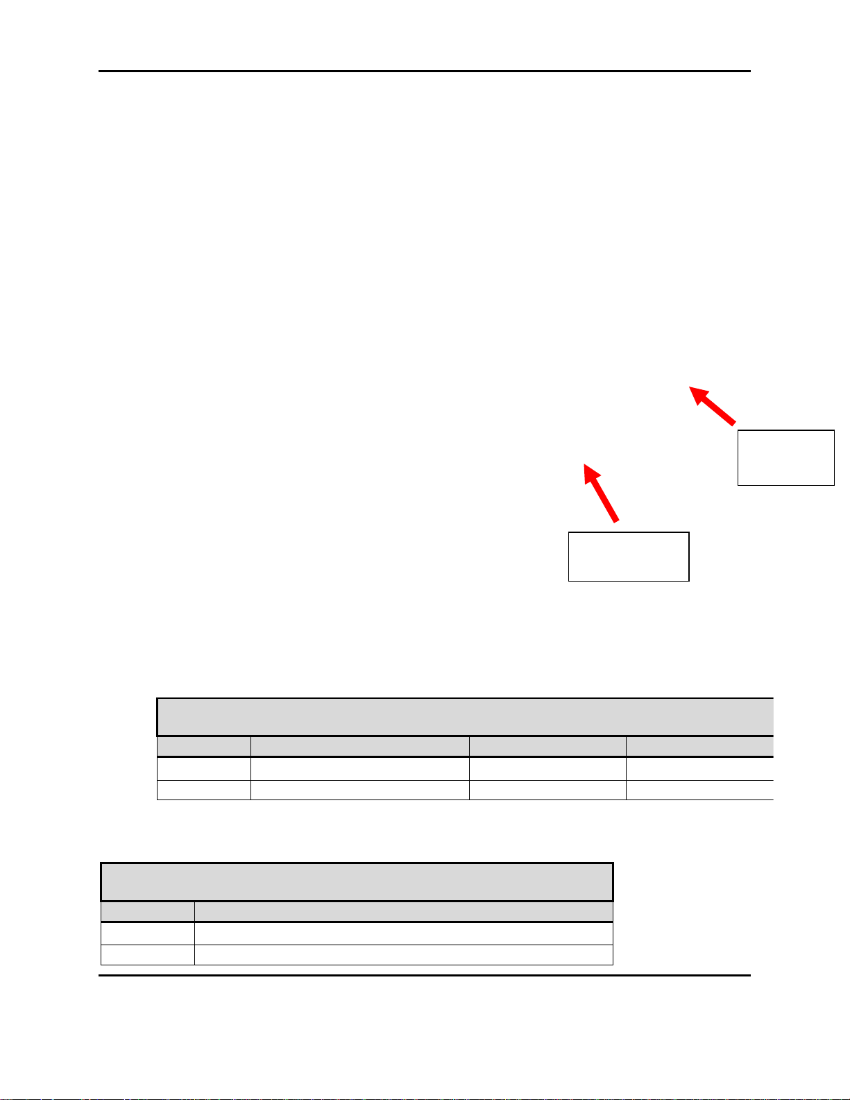
Table 2-8. J1: Main IF Pin Definitions
Pin
Description
1
8-18 VDC
2
Ground
Table 2-7. Nano Hardware Interface
Connector
Description
EDL Connector
Mating Connector
J1
Main IF: Header 2x20
Molex 501571-4007
Molex 501189-4010
J2
Camera IF: Header 2x10
Molex 501571-2007
Molex 501189-2010
J2:
Camera IF
J1: Main IF
Document Number: AE301628-001
Revision: B Date: 3 October 2019
Figure 2-3 Nano Physical I/O
Aeronix Proprietary
7

Form #: OP_01_TM
Title: Aeronix Data Links – EDL Nano Products User Guide
3
8-18 VDC
4
Ground
5
8-18 VDC
6
Ground
7
Platform RS-232 Rx
8
USB OTG VBUS
9
Platform RS-232 Tx
10
USB OTG DP
11
Ext GPIO 0 – External Tx Enable (1.8V)
12
USB OTG DN
13
Ext GPIO 2 – External Rx Enable (1.8V)
14
Ground
15
Ext GPIO 1
16
Console RS-232 Tx
17
Ext GPIO 3
18
Console RS-232 Rx
19
Green LED
20
Ground
21
Red LED
22
Ground
23
RX TX Enable
24
Ground
25
TAMPER
26
Ground
27
VBUS 5V
28
USB Host DN
29
Ground
30
USB Host DP
31
Ether2 Tx+
32
Ether1 Tx+
33
Ether2 Tx-
34
Ether1 Tx-
35
Ground
36
Ground
37
Ether2 Rx+
38
Ether1 Rx+
39
Ether2 Rx-
40
Ether1 Rx-
Document Number: AE301628-001
Revision: B Date: 3 October 2019
Aeronix Proprietary
8

Form #: OP_01_TM
Title: Aeronix Data Links – EDL Nano Products User Guide
Table 2-9. J2: Camera IF Pin Definitions
Pin
Description
1
3 VDC
2
Ground
3
CAM SDA
4
CAM CLK
5
CAM SCL
6
CSI D3P
7
CAM EN
8
CSI D3M
9
CAM RST#
10
Ground
11
CSI D0P
12
CSI D2P
13
CSI D0M
14
CSI D2M
15
Ground
16
Ground
17
CSI D1P
18
CSI CLKDP
19
CSI D1M
20
CSI CLKDM
2.3.1. USB OTG
USB OTG port is currently only used to download initial firmware. Software to use the USG
OTG to recognize other applications has not been implemented.
2.3.2. USB Host
Software has not been formally tested.
2.3.3. Ethernet 1 & 2
Ethernet ports are both IEEE802.3 compliant 10/100 Mbps connection. Ethernet 1 is the primary
Ethernet for the radio. Ethernet 2 currently is not configurable and usable on the radio.
2.3.4. Console RS-232
The Serial interface allows direct communication with the radio’s control processor. This
interface is a RS-232 standard interface. Port is configured as 8-N-1, 115200 BAUD. This port
provides the radio’s login console. You can login with administrative privileges by entering
“root” at the login prompt and password “1234”.
Document Number: AE301628-001
Revision: B Date: 3 October 2019
Aeronix Proprietary
9
Form #: OP_01_TM
Title: Aeronix Data Links – EDL Nano Products User Guide
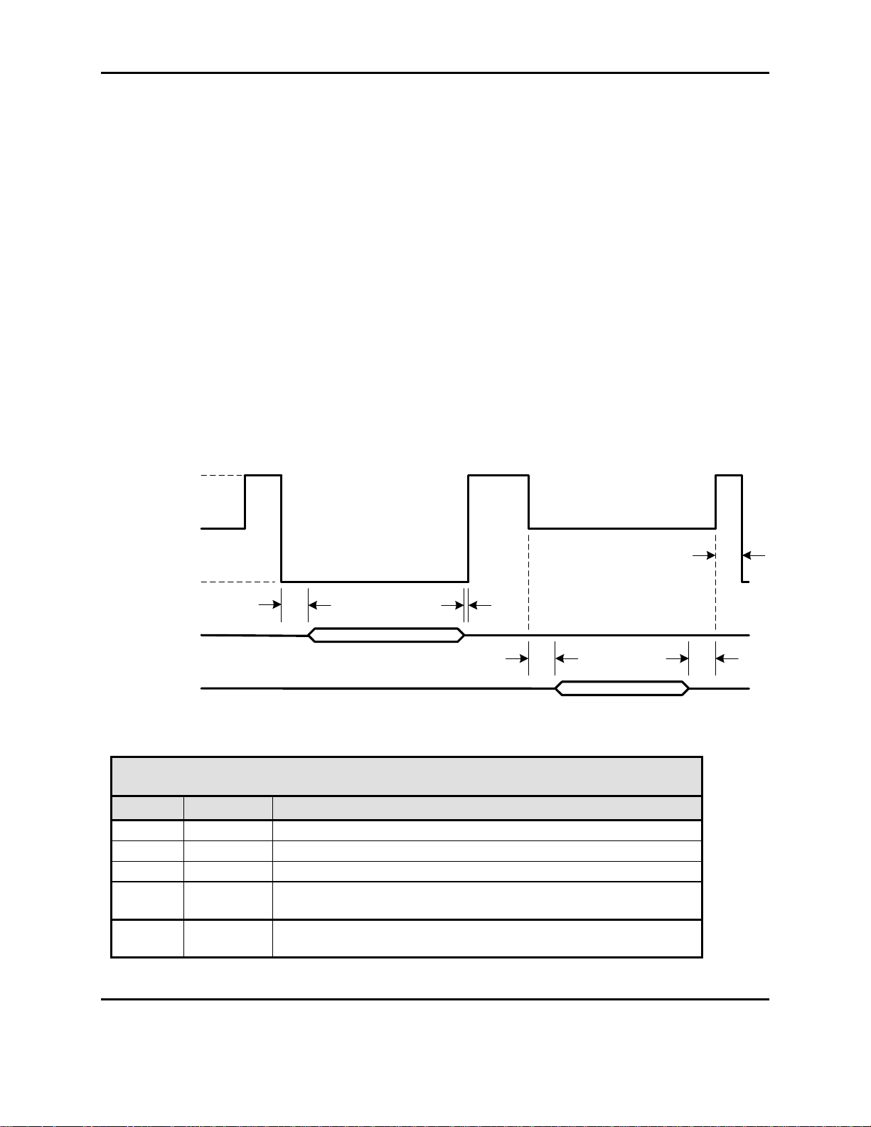
Table 2-10 GMSK 14 MHz T/R SW Timing
Marker
Time (us)
Description
t1
TBD
Minimum time from Tx Enable Active to start of Transmit Out
t2
TBD
Minimum time from Transmit Out Complete to Tx Enable Inactive
t3
TBD
Minimum Time from Rx Enable Active to Receive energy
t4
TBD
Minimum time from Receive Energy Complete to Rx Enable
Inactive
t5
TBD
Minimum switching time, ie minimum amount of Idle time before a
radio will switch between Rx and Tx state or Rx and Rx state
Tx
Rx
t1
t3 t4
0V (Tx)
V/2 (Rx)
V (Idle)
Rx Tx Enable
Tx Out
Rx Open
t2
t5
2.3.5. Platform RS-232
Serial interface is for serial to serial communication. This interface is a RS-232 standard
interface. The debug port is configured as 8-N-1, the BAUD rate is configurable via the webgui
or SNMP. This interface is used to pass serial data from a BS serial port to one of its SS serial
port.
2.3.6. P1 Antenna Interface TxRx 1
The antenna interface is an SMA connector that provides both input and output RF signalling.
2.3.7. P2 Antenna Interface Rx 2
The antenna interface is an SMA connector that provides input RF signalling.
2.3.8. Tx Rx Enable
The Tx/Rx Enable is a three state condition. It requires an external pull-up resistor of 4.7 kilo
ohms to supply voltage V (customer determined with a max of 5V), see diagram below.
Figure 2-4 TR SW Timing
Document Number: AE301628-001
Revision: B Date: 3 October 2019
Aeronix Proprietary
10

Form #: OP_01_TM
Title: Aeronix Data Links – EDL Nano Products User Guide
Table 2-11 OFDM T/R SW Timing
Marker
Time (us)
Description
t1
12 us
Minimum time from Tx Enable Active to start of Transmit Out
t2
0
Minimum time from Transmit Out Complete to Tx Enable Inactive
t3
80 us
Minimum Time from Rx Enable Active to Receive energy
t4
11 us
Minimum time from Receive Energy Complete to Rx Enable
Inactive
t5
10.5 us
Minimum switching time, ie minimum amount of Idle time before a
radio will switch between Rx and Tx state or Rx and Rx state
2.3.1. Tx Rx Enable 4 State (OFDM only)
External Tx and Rx control lines with 1.8V logic.
2.3.2. External GPIO 1 & 3
Not Used
2.3.3. Red and Green LED
The external Red and Green LEDs will give the user some basic status of the radios current state.
Green only LED on -> The NANO is in sync with another radio
Red only LED on -> The Nano’s RF is turned off via the software Tx/Rx enable/disable
setting.
Green and Red LED on (Yellow) -> The NANO RF is on, but NOT in sync with another
radio.
2.3.4. Tamper
Not Used
2.3.5. RF Output Power
The NANO output power will remain unchanged regardless of the RF environment. The NANO
output power is based on frequency and is calibrated per Radio Card. Each radio will have its
own calibration programmed and available for the user to view. Each NANO may vary from 1-2
dB of output power. See section 7.1 NANO output power for more information on determining
the output power measured on a particular frequency.
3. System Configuration
3.1. Aeronix GUI interface
This simple yet powerful GUI uses uncomplicated intuitive screens to allow the average user the
ability to:
Document Number: AE301628-001
Revision: B Date: 3 October 2019
Aeronix Proprietary
11

Form #: OP_01_TM
Title: Aeronix Data Links – EDL Nano Products User Guide
Configure the system for their network
Make the system operational
Perform maintenance
The GUI screens and all their respective elements are described in the following subsections.
To get to the main page, type the following URL: http://<ip address of the radio>/
The recommended browsers to use are Internet Explorer Version 7 or newer and Mozilla Firefox.
3.2. SNMP interface
The NANO can be configured to run the Aeronix SNMP agent, and process SNMP (Simple
Network Management Protocol) requests using the radio’s IP. This allows the user to configure
and monitor the radio over an IP network.
3.3. Startup
Each unit is configured with an IP address. Using the IP address, one can access the GUI which
can be used for configuring the radio to the user’s specifications. The typical factory default IP
address that is set from the factory is 192.168.1.1 and the units default configuration is that of
subscriber 1, unless specified otherwise. To browse the GUI type in the IP address of the unit in
an internet browser. More information about the GUI screens and how to configure the unit can
be found in this section.
3.4. Radio Maintenance Login
3.4.1. Using Serial Port A
1) Make sure antenna port has a load on it.
2) Apply appropriate power to unit.
3) Connect to Serial A port with terminal emulator. (Baud = 115200, 8-N-1 no flow
control)
4) Login by typing “root”
5) Enter password “1234”.
6) $ cd /mnt/jffs2
3.5. Ethernet alias IP address
The user can always access the radio over its Ethernet alias IP address of 169.254.1.1. This IP is
consistent so if the user needs to access the GUI or SNMP and has forgotten the configured IP
address for the radio’s Ethernet, then the user can access 169.254.1.1.
3.6. WEB Based GUI System Configuration
This simple yet powerful GUI uses uncomplicated intuitive screens to allow the average EDL
user:
Document Number: AE301628-001
Revision: B Date: 3 October 2019
Aeronix Proprietary
12

Form #: OP_01_TM
Title: Aeronix Data Links – EDL Nano Products User Guide
A
This section displays the current mode radio is in and the
HTML links to the all of the pages available.
B
The radio’s configured name and IP address, located on the
web page tab.
Configure the system for their network
Take the system operational
Perform maintenance
The GUI screens and all their respective elements are described in the following subsections.
To get to the main page, types the following URL: http://<ip address of the radio>/
The recommended browsers to use are Internet Explorer Version 8 or newer and Mozilla Firefox.
The sections below show screen shots using either OFDM or GMSK mode. If there is a
difference in the GMSK versus OFDM screen captures then both captures will be displayed.
3.6.1. Base Station Status Page
The base station status page is the default page displayed when the radio’s IP address is entered.
The status page lists the current active subscribers received by the BS. It also lists the current
configuration of the base station.
There are attributes each web page share, these are highlighted by items A and B in the image
below.
Document Number: AE301628-001
Revision: B Date: 3 October 2019
Aeronix Proprietary
13

Form #: OP_01_TM
Title: Aeronix Data Links – EDL Nano Products User Guide
Table 3-1. Base Station Status Page
Field/Control
Description
1
Status
Status displays a subset of current settings.
MAC Address – The IEEE 802.16 MAC address
of the base station
Current Channelization – Displays the
channelization of the base station. The
channelization may be changed on the Radio
Control Screen.
Current Channel – The current 802.16 specified
channel that the base station uses for transmit
and receive. The channel may be changed on
the Radio Control screen.
BS Estimated EIRP – Displays the estimated
EIRP of the base station based upon user
configured gain a loss values. (Est Tx Pwr +
Antenna Gain – External Tx Cable Loss –
Antennal Cable Loss – Internal Tx Loss )
Tx - Provides the status of the transmit portion of
the unit. (On/Off) The status may be changed
on the Radio Control screen.
Rx - Provides the status of the receive portion of
the unit. (On/Off) The status may be changed
on the Radio Control screen.
Transec Status – Displays the status of Transec
(on or off). The Transec status can be changed
on the Admin Screen.
2
Board Details
Display Temperature
CPU Temperature – Displays the temperature
reported by the processor in Celsius and
Fahrenheit
RF Temperature – Displays the temperature
reported by the AD9361 chip on the RF card in
Celsius and Fahrenheit
3
Front Panel
Displays PHY status on an interval basis.
Base is a constant green light if the radio is
configured as a Base Station
Sync is off on the base station when no
subscribers are registered and is illuminated
continuously when subscribers are registered.
Recv is green when the radio is receiving
messages
Xmit is green when the radio is transmitting data
Alarm
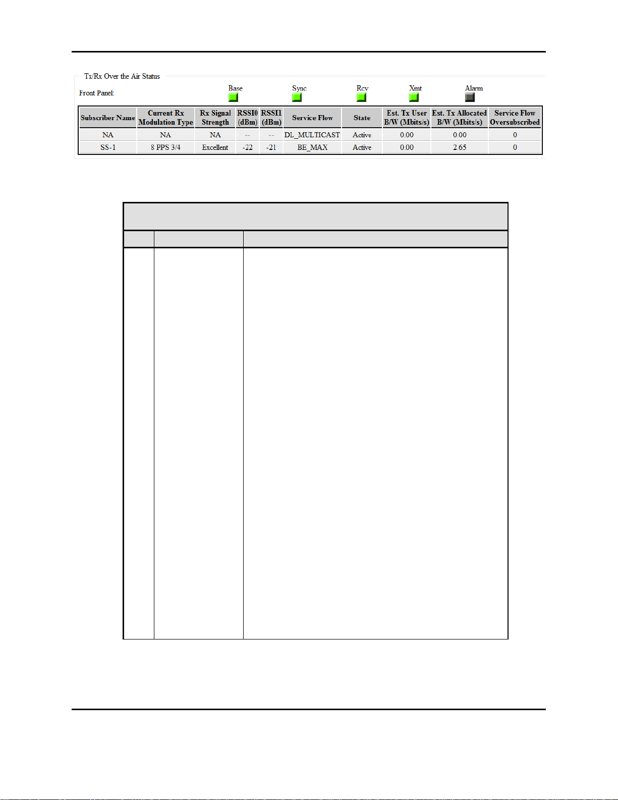
Figure 3-1 BS GMSK Status
Document Number: AE301628-001
Revision: B Date: 3 October 2019
Aeronix Proprietary
14

Form #: OP_01_TM
Title: Aeronix Data Links – EDL Nano Products User Guide
Table 3-1. Base Station Status Page
Field/Control
Description
4
Tx/Rx Over the
Air Status
The first part of the Tx/Rx Status Table Displays the
receive status of each subscriber connection. The
second part of the table is the amount of data the BS is
transmitting to each active SS.
Subscriber Name - Configured Subscriber’s
name.
Current Modulation Type – Contains the current
modulation/FEC type for the subscriber
connection. The display show the modulation of
the receive frame at the time sampled.
Rx Signal Strength: Contains an assessment of
the receive signal strength.
RSSI (dBm) – Display the RSSI value measured
at the P1 antenna port.See Figure 3-2 BS Status
GMSK RX Dual mode for RX Dual mode
display
Service Flow – Identifies the service class of the
service flow for the connection.
State – Displays the state of the connection.
The valid values are provisioned and active.
Est User B/W (Mbits/sec) – Displays the
estimated bandwidth in megabits per second
being used by the connection in the transmit
direction.
Est Allocated B/W (Mbits/sec) – Displays the
estimated bandwidth in megabits per second
being allocated to the connection in the transmit
direction.
Service Flow Oversubscribed – Displays the
number of Ethernet packets dropped because
the number of packets for that specific service
flow has reached its limit and is full.
3.6.1.1. Base Station Status Page in Receive Dual
When the user enables RX Dual on the Radio control page the second receive RSSI will be
reported on the RSSI1 column on the Tx/Rx Over the Air Status section.
Document Number: AE301628-001
Revision: B Date: 3 October 2019
Aeronix Proprietary
15
Form #: OP_01_TM
Title: Aeronix Data Links – EDL Nano Products User Guide
Table 3-2. Base Station Status Page RX Dual Mode
Field/Control
Description
Tx/Rx Over the
Air Status
The first part of the Tx/Rx Status Table Displays the
receive status of each subscriber connection. The
second part of the table is the amount of data the BS is
transmitting to each active SS.
Subscriber Name - Configured Subscriber’s
name.
Current Modulation Type – Contains the current
modulation/FEC type for the subscriber
connection. The display show the modulation of
the receive frame at the time sampled.
Rx Signal Strength: Contains an assessment of
the receive signal strength.
RSSI0 (dBm) – Display the RSSI value
measured at the P1 antenna
RSSI1 (dBm) – Display the RSSI value
measured at the P2 antenna
Service Flow – Identifies the service class of the
service flow for the connection.
State – Displays the state of the connection.
The valid values are provisioned and active.
Est User B/W (Mbits/sec) – Displays the
estimated bandwidth in megabits per second
being used by the connection in the transmit
direction.
Est Allocated B/W (Mbits/sec) – Displays the
estimated bandwidth in megabits per second
being allocated to the connection in the transmit
direction.
Service Flow Oversubscribed – Displays the
number of Ethernet packets dropped because
the number of packets for that specific service
flow has reached its limit and is full.
Figure 3-2 BS Status GMSK RX Dual mode
If the OFDM base station is no longer receiving valid receive information for a connection, the
row for that connection will be displayed in red, which could mean the data is stale. If the base
Document Number: AE301628-001
Revision: B Date: 3 October 2019
Aeronix Proprietary
16

Form #: OP_01_TM
Title: Aeronix Data Links – EDL Nano Products User Guide
station is a GMSK base station the row will be displayed in red. For both modes, if the reception
loss continues for a period of time the base station deregisters the subscriber and the row
disappears from the display.
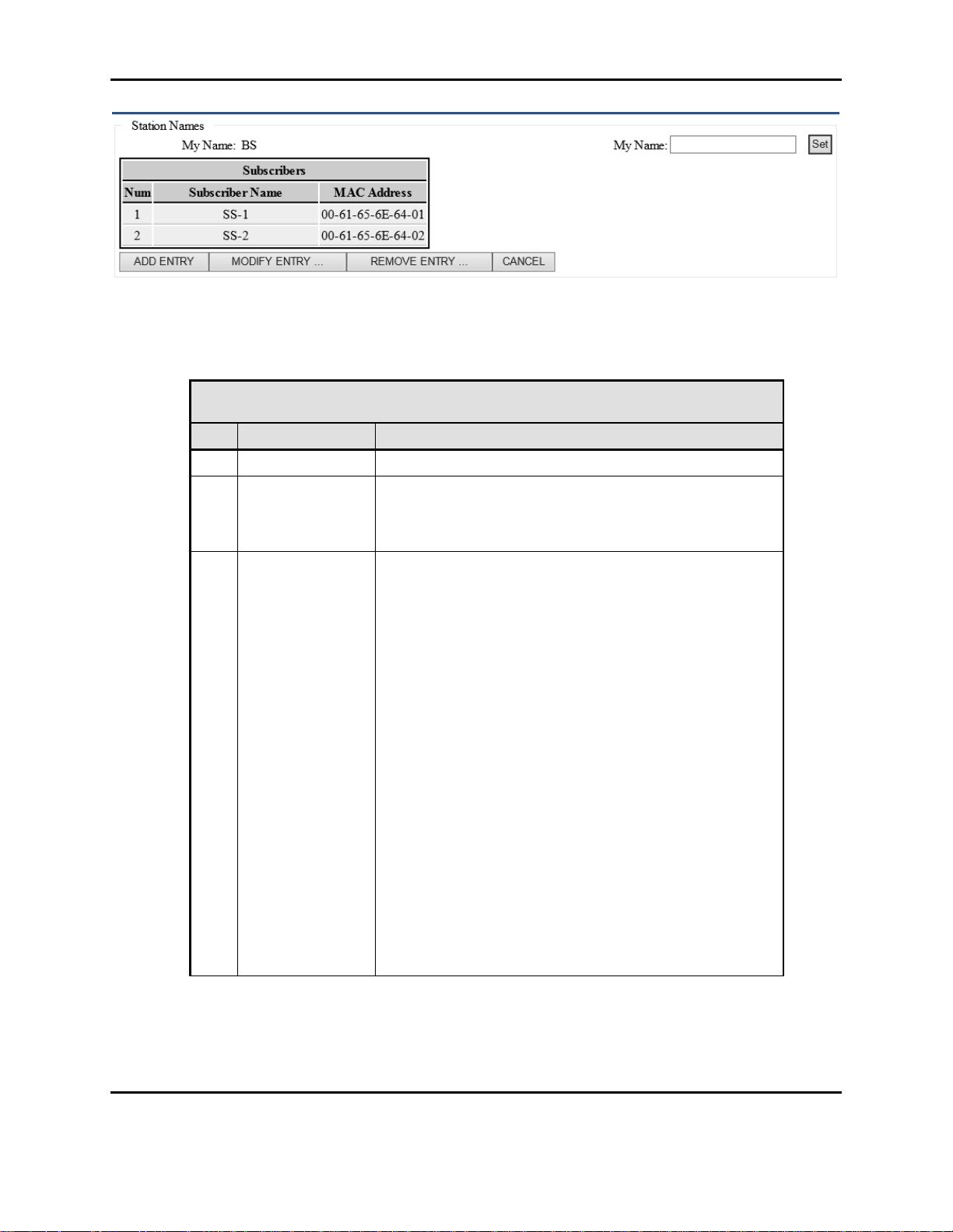
3.6.2. Base Station Admin Page
The admin page allows administration of station names for the base station and subscribers. It
also provides the capability to enable and disable TRANSEC and the selection of the TRANSEC
key. Start script generation and software download are also supported on the admin page.
Figure 3-3 BS Admin Page
Document Number: AE301628-001
Revision: B Date: 3 October 2019
Aeronix Proprietary
17
Form #: OP_01_TM
Title: Aeronix Data Links – EDL Nano Products User Guide
Table 3-3. BS Admin Page Station Names
Field/Control
Description
1
My Name
Displays the current name of the base station.
2
My Name
Provides the capability to change or set the name of the
base station. Type in the desired name and click the set
button. The new name will automatically be distributed
throughout the system
3
Subscribers
Relates a Subscriber’s MAC Address with a user friendly
name.
Number : Auto incrementing number.
Subscriber-Name: A unique name for the
Subscriber, this is an alphanumeric string that
will identify the SS.
MAC Address: MAC – the IEEE 802.16 MAC
address of the subscriber station. The MAC
address should be of the format 00-61-65-6E64-XX where XX is the subscriber number in the
system. The subscriber number is configured in
the start script as part of the start script
generation which is described later in this
section of the document. The user can
configure up to 32 subscribers for the network.
Add Entry Button – Add Subscriber to network
Modify Entry – Modify Subscriber Station entry
Remove Entry – Remove Subscriber Station
Note: A subscriber’s information must be added here
first before moving on to adding a Provisioned Service
Flow for it.
Note: The BS will only allow a max of 10 Subscribers to
be configured.
Figure 3-4 BS Admin Station Names
Document Number: AE301628-001
Revision: B Date: 3 October 2019
Aeronix Proprietary
18

Form #: OP_01_TM
Title: Aeronix Data Links – EDL Nano Products User Guide
Table 3-4. BS Admin Transec Key Mgmt
Field/Control
Description
Transec Key
Management
Displays the settings for Transec capability.
Transec - Displays current Transec state
(ON/OFF).
Transec Enable/Disable buttons - Ability to
enable or disable.
Key Length drop down menu – Allows user to
specify the number of bits for the Transec Key
Load Key – Allows the ability to change the
Transec Key in hexadecimal based on Key
length.
Current Key – Displays the current key.
3.6.2.1. BS Admin Transec Key Management
Figure 3-5 BS Admin Transec Key Mgmt
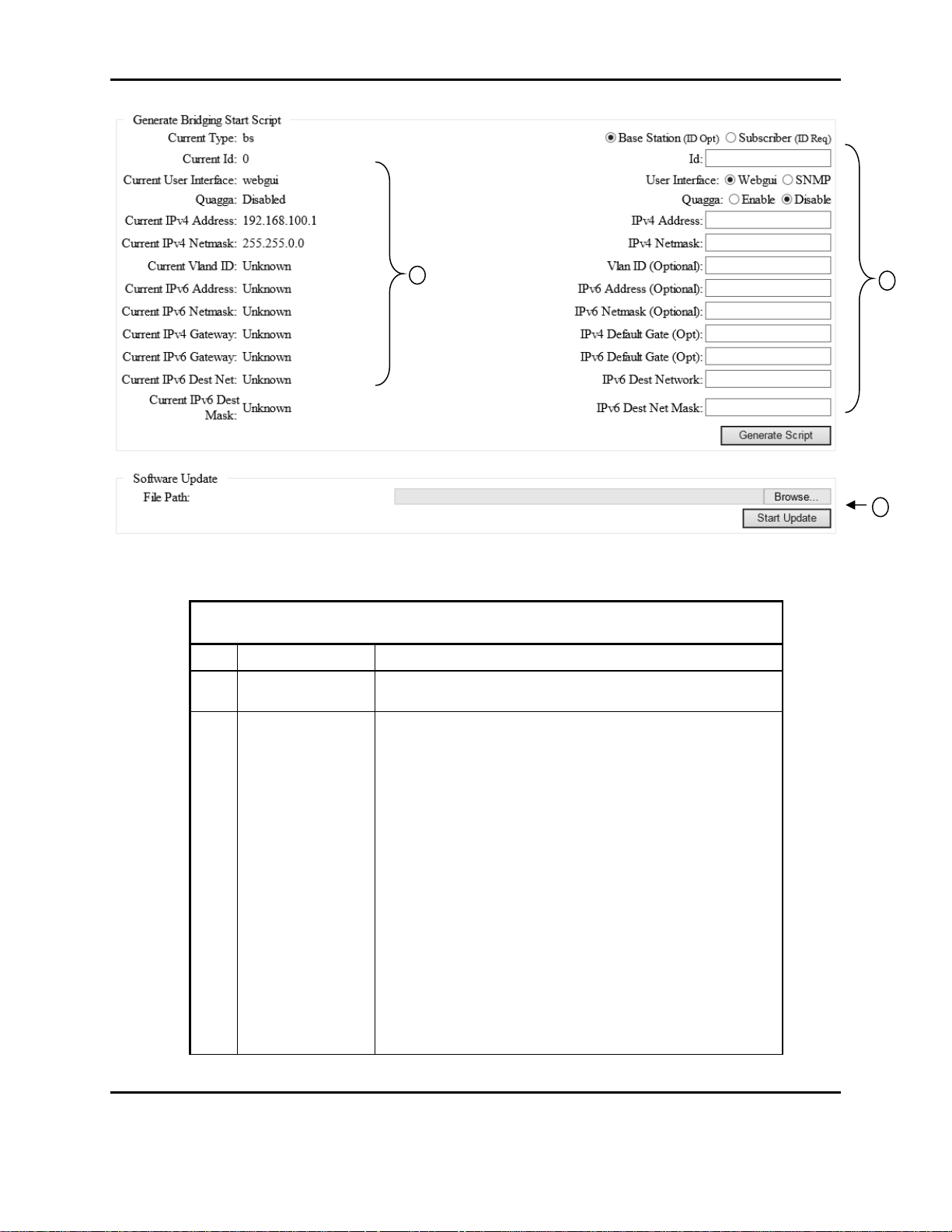
3.6.2.2. BS Admin Bridging Start Script and Software Update
Bridging is the default mode for operating the units. The Generate Bridging Start Script section
of the admin page allows for configuration of the start script. Once the configuration is set by
selecting the Generate Script button the unit must be rebooted or power cycled for the
configuration to take effect.
Document Number: AE301628-001
Revision: B Date: 3 October 2019
Aeronix Proprietary
19
Form #: OP_01_TM
Title: Aeronix Data Links – EDL Nano Products User Guide
Table 3-5. BS Admin Start Script and S/W Update
Field/Control
Description
1
Current Start
Script
The current start script parameters.
2
Generate Script
User can change the mode the radio boots in or the IP
address,etc. The unit should not be powered cycled
while script generation is in process.
Type radio buttons: Select BS or SS for type
Id: If setting up start script as SS enter its
Subscriber Number.
User Interface radio buttons: NANO can be
statistics and configuration can be monitored
using either the webgui interface or the SNMP
interface
o Click on the radio button for the desired
interface
Quagga radio buttons: Option to enable
additional network routing software suite
providing implementations of Open Shortest
Path First (OSPF). Note there is user
configuration necessary to implement Quagga,
this information is not covered in this document.
1
2
3
Figure 3-6 BS Bridging Script and S/W Update
Document Number: AE301628-001
Revision: B Date: 3 October 2019
Aeronix Proprietary
20

Form #: OP_01_TM
Title: Aeronix Data Links – EDL Nano Products User Guide
Table 3-5. BS Admin Start Script and S/W Update
Field/Control
Description
IPv4 Address: Provides the capability to set a
new IPv4 address for the unit.
IPv4 Netmask: Provides the capability to set a
new IPv4 netmask address for the unit
IPv4 Default Gate (Opt) : Optional ability to
configure an IPv4 default gateway.
Vlan ID (Optional) : Allows user to add a VLAN
ID to IP packets coming from radio. The radio
will pass VLAN tagged packets unmodified, so
this does not need to be set to allow VLAN
packets to flow through the radio. Only if
communication to the radio needs to have a
VLAN ID.
IPv6 Default Gate (Opt) : Optional ability to
configure an IPv6 default gateway.
IPv6 Address (Optional) : Optional IPv6 address
for the Ethernet (Note : current release of EDL
does not support IPv6)
IPv6 Netmask (Optional) : Optional IPv6
netmask for IPv6 address (Note: current release
of EDL does not support IPv6)
Generate Script Button : Generates a new start
script for the unit with the values input in the
“Generate Bridging Start Script” section of the
Admin page. Once the script has been
generated, the unit must be rebooted or power
cycled for the new values to take effect. The
unit should not be power cycled while script
generation is in process.
3
Software Update
Allows user to select a signed package file provided by
the manufacturer to update the software on the unit.
File Path – Allows users to browse to location
where the package file resides.
Start Update - Selection of the start update
button starts the software update using the
factory signed package file specified in the File
Path. Once the update process begins, any
interruption can render the box unusable and
require its return to the factory.
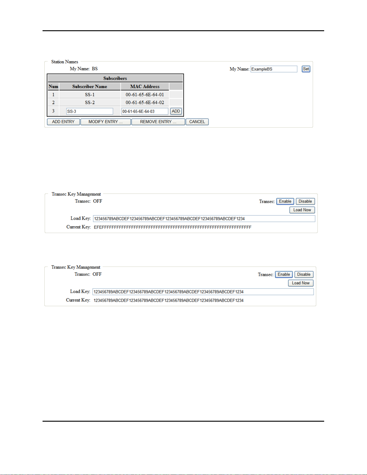
3.6.2.3. Example Adding a SS Entry
A subscriber must be added here in order to continue configuring that subscriber in network.
Enter a name for the subscriber and then a IEEE 802.16 MAC address for the subscriber station. The
MAC address should be of the format 00-61-65-6E-64-XX where XX is the subscriber number in the
system. The subscriber number is configured in the start script as part of the subscriber start script
generation which is described later in this section of the document.
Document Number: AE301628-001
Revision: B Date: 3 October 2019
Aeronix Proprietary
21
Form #: OP_01_TM
Title: Aeronix Data Links – EDL Nano Products User Guide
The system will allow the user to configure 10 Subscribers.
Figure 3-7 Example Adding a SS entry
3.6.2.4. Example Modify Transec Key
The following screen shows and example for updating a Transec key in the base station. The key
is a 256 bit hexadecimal value. User must enter a new value in the ‘Load Key’ entry box. Then
the user must click on the ‘Load Now” Button.
Figure 3-8 Example Modify Transec Key
Once the user click on the ‘Load Now’ button the Transec key will be updated.
Figure 3-9 Example Modify Transec Key Result
In order for the Transec Key to be saved to the database for future use, the user must select the
‘Save Settings’ Button on the left menu (not shown in picture above, refer to 3.6.15.1 Save
Settings Button).
3.6.2.5. Generate Bridging Start Script Example
Bridging is the default mode for operating the units. The Generate Bridging Start Script section
of the admin page allows for configuration of the start script. Once the configuration is set by
selecting the Generate Script button the unit must be rebooted or power cycled for the
configuration to take effect. In this example below depicts new BS start script with an IPv4
address of 10.1.100.1.
Document Number: AE301628-001
Revision: B Date: 3 October 2019
Aeronix Proprietary
22
 Loading...