

Aeronix ACTAE1000 User Manual

Certification Exhibit
FCC ID: T2K-ACTAE1000
IC: 11123A-AE1000
FCC Rule Part: 15.247
IC Radio Standards Specification: RSS-210
ACS Project Number: 12-0550
Manufacturer: Aeronix, Inc.
Model: AE1000
Manual
5015 B.U. Bowman Drive Buford, GA 30518 USA Voice: 770-831-8048 Fax: 770-831-8598
ACT
Title: ACT Module Integration Guide
Aeronix #: AE301128-001
Rev -
5/21/2013
Prepared by:
535 N Pleasantburg Dr, Suite 114
Greenville, SC 29607
Aeronix Proprietary
Title: ACT Module Integration Guide
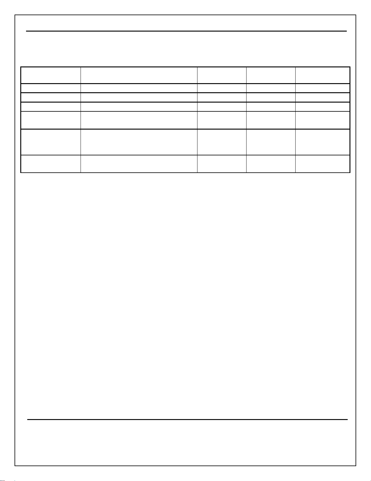
Document Revision History
Version/Revision Description of Change Chg’d By Chg/Rel # Date
- Initial Baseline S. Priddy 1 May 2013
- Incorporate Design Review Feedback S. Priddy 20 May 2013
Add released part # S. Priddy 21 May 2013
All references to model number are
now “AE1000”
Added General Statement for FCC
compliance.
Removed “DRAFT” watermark
Renamed Section 9.5 to “Module
Labeling”
P. Baron July 2, 2013
P. Baron August 8, 2013
P. Baron
August 21,
2013
Document Number: AE301128-001
Revision: - Date: 8/8/2013
Page ii
Aeronix Proprietary
Form #: AX0005 03 February 2005
REV: B

Title: ACT Module Integration Guide
Table of Contents
1
PURPOSE .............................................................................................................................. 3
2
ACRONYMS ........................................................................................................................... 3
3
REFERENCE DOCUMENTS .................................................................................................. 3
4
SPECIFICATIONS .................................................................................................................. 4
4.1
Environmental ....................................................................................................................................................................... 4
4.1.1 Operating Temperature .................................................................................................................................... 4
4.1.2 Storage Temperature ....................................................................................................................................... 4
4.1.3 Operating Humidity .......................................................................................................................................... 4
4.2
Physical .................................................................................................................................................................................. 4
4.2.1 Weight .............................................................................................................................................................. 4
4.2.2 Approximate PCB Dimensions ......................................................................................................................... 4
5
SYSTEM COMPONENTS ....................................................................................................... 4
5.1
Supported USB Cable ........................................................................................................................................................... 4
••••
Phihong USA IPUSB1MS-R ................................................................................................................................................ 4
5.2
PCB Module Assembly ......................................................................................................................................................... 4
5.3
USB Cable .............................................................................................................................................................................. 5
5.4
Power Supply ......................................................................................................................................................................... 5
5.4.1 Supported Power Supply ................................................................................................................................. 5
5.4.2 Ratings ............................................................................................................................................................. 5
5.4.3 Connector ......................................................................................................................................................... 5
5.5
Battery.................................................................................................................................................................................... 5
5.6
Euro Block Pluggable Terminal Block ................................................................................................................................ 5
5.7
Antennas ................................................................................................................................................................................ 6
5.7.1 Cellular ............................................................................................................................................................. 6
5.7.2 GPS .................................................................................................................................................................. 6
5.7.3 Proprietary 915MHz RF ................................................................................................................................... 6
6
MODULE CONNECTIONS ..................................................................................................... 7
6.1
Top View ................................................................................................................................................................................ 8
6.2
Bottom View .......................................................................................................................................................................... 8
Document Number: AE301128-001
Revision: - Date: 8/8/2013
Page 1
Aeronix Proprietary
Form #: AX0005 03 February 2005
REV: B

Title: ACT Module Integration Guide
6.3
Euro Block Receptacle .......................................................................................................................................................... 9
6.4
USB Micro-B ......................................................................................................................................................................... 9
6.5
DB9 ......................................................................................................................................................................................... 9
6.6
Battery Connector ............................................................................................................................................................... 10
6.7
SIM Holder .......................................................................................................................................................................... 10
6.8
Antenna Connectors ........................................................................................................................................................... 11
6.9
Cellular Antenna ................................................................................................................................................................. 11
6.10 RF Antenna ......................................................................................................................................................................... 11
6.11 GPS Antenna ....................................................................................................................................................................... 12
7
ASSEMBLY ........................................................................................................................... 12
7.1.1 Connections ................................................................................................................................................... 12
8
OPERATION ......................................................................................................................... 12
8.1
Cellular Connection (LED 1) ............................................................................................................................................. 12
8.2
Server Connection (LED 2) ................................................................................................................................................ 12
8.3
GPS (LED 3) ........................................................................................................................................................................ 13
8.4
RF Connection (LED 4) ...................................................................................................................................................... 13
8.5
DC Power ............................................................................................................................................................................. 13
9
CERTIFICATION STATEMENTS ......................................................................................... 13
9.1
FCC Part B .......................................................................................................................................................................... 13
9.2
RF Exposure ........................................................................................................................................................................ 13
9.3
Industry Canada Specific Statements ............................................................................................................................... 13
9.4
License Exempt ................................................................................................................................................................... 14
9.5
Labeling ............................................................................................................................................................................... 14
Document Number: AE301128-001
Revision: - Date: 8/8/2013
Page 2
Aeronix Proprietary
Form #: AX0005 03 February 2005
REV: B

Title: ACT Module Integration Guide
1 Purpose
The purpose of this document is to describe the ACT Module AE1000 integration and operation.
2 Acronyms
SIM Subscriber Identity Module
GPIO General Purpose Input / Output
GPO General Purpose Output
GND Electrical Ground Reference
VDC Voltage Direct Current
VAC Voltage Alternating Current
mA Millamperes
A/D Analog-to-Digital
mAh Milliampere Hours
PCB Printed Circuit Board
RF Radio Frequency
3 Reference Documents
The following documents of the latest issue, unless distinctly noted, will form a part of this specification to
the extent specified herein. In the event of conflict between the documents referenced herein and the contents
of this specification, this specification will take precedence.
NONE
Document Number: AE301128-001
Revision: - Date: 8/8/2013
Page 3
Aeronix Proprietary
Form #: AX0005 03 February 2005
REV: B
 Loading...