

Page 1
aero
naut
SHK
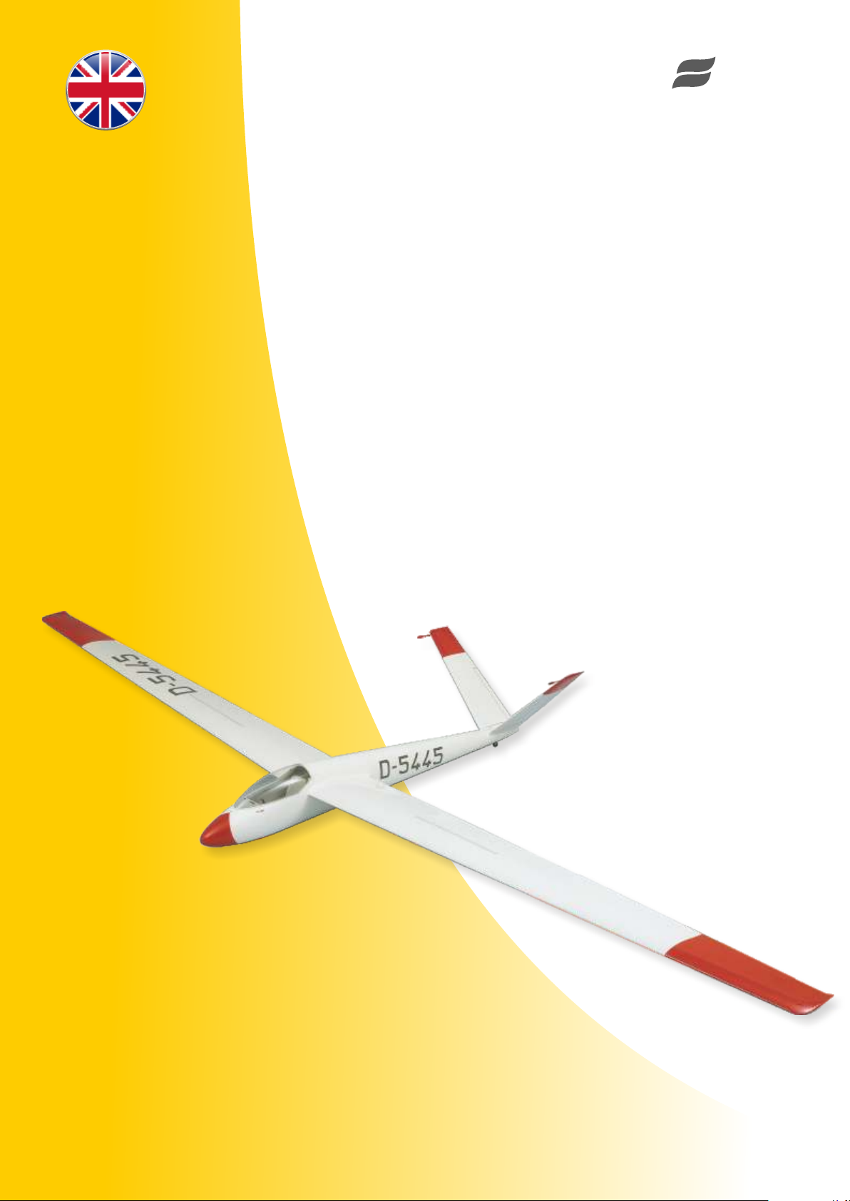
RC-Sailplane
Order-No. 1125/01
Page 2

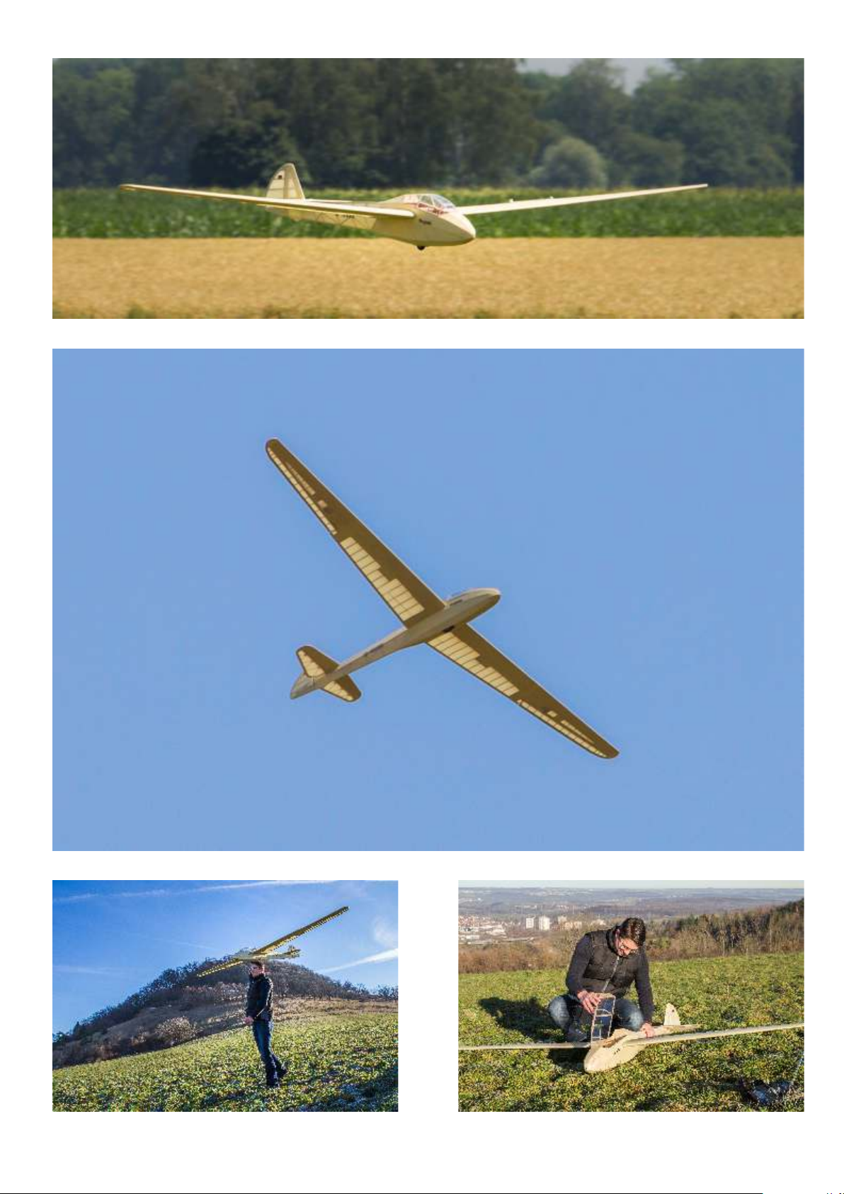
SHK Sailplane Order-No. 1125/01
Technical Data
Wingspan 4,000 mm
Length 1,501 mm
Wing area 82 dm²
Flying weight ca. 4,300 g
Wing loading 52.4 g/dm²
Wing airfoil Selig S4233 mod.
RC-functions
rudder, elevator (V-tail)
ailerons
spoiler
optional: retractable wheel, tow release (Note: Sheet 17 contains
parts for tow release servo tray)
Replacement parts
GRP fuselage, white 1125/02
GRP tail cap, white 1125/03
Canopy, frame and vac.-molded
cockpit parts 1125/04
Pair of wing panels 1125/05 (foam(obechi)
Pair of tailpanels 1125/09 (foam/balsa)
Wings and tailplane kit 1125/06 (laser-cut parts)
V-tail bellcranks 7492/20
Recommended components
Ailerons: 13 mm thick servos or special wing servos
V-tail and spoilers: standard servos > 3 kgcm
Battery: LiPo or NiMH > 2500 mAmps
Options
Retractable wheel: Order-No. 7358/12
Tow release: servo > 6 kgcm
We recommend our aero-pick modellers´s
pins for building.
Order-No.: 7855/02
Introduction
This version of the SHK kit includes a GRP fuselage and conventional wings and tailplane as opposed to foam wings and tailplane of the previous version
of the SHK. The fuselage is completed as described in this manual, the new built-up wings and tailplane will fit perfectly. Please refer to the included
construction drawings as well as to the parts list in this manual for reference.
A special type of building jig, which is typical for most aero-naut models, is used for the wings and tailplane and speeds up the building process
considerably. Please follow the illustrated step-by-step instructions in this manual for best results.
Wood (and plywood too) is subject to tolerances. Please check all parts for an easy fit, before you glue. Correct, if necessary.
Parts for wings and tailplane are laser-cut and numbered. Please use the parts list in this manual to identify the included strip wood. Use a sharp
modelling knife to cut parts from laser sheets. Use sandpaper to clean any residue of the laser cutting process from the individual parts to get good
contact surfaces for gluing. Always check that parts fit perfectly. Correct, if necessary, before you glue. Give glue sufficient time to dry before you begin
with the next step.
We recommend white glue (if not otherwise noted) for gluing, which offers good strength and low weight. White glue retains a certain degree of
elasticity even after the glue has cured und will stand up to any loads which occur during flying.
Tip: Wings and tailplane of your SHK use maple veneer as a sheeting material. This veneer is reinforced with a cotton fabric on the underside for extra
strength and good handling characteristics. For good sanding results seal edges of veneer parts with wood primer to glue individual strands of fabric
together.
Page 3

Fuselage
These building instructions include a reduced-scale drawing of the die-stamped plywood sheets. Write the part number on each component using a soft
pencil, referring to this drawing. Cut out the parts from the die-stamped sheets using a balsa knife. All parts should be trial-fitted and trimmed as required
before installing them permanently.
You may wish to deviate from the sequence described in these building instructions. Please think carefully about the result of your actions! Use the
building instructions and parts list constantly while building the model, and use the actual servos and receiver battery to ensure the best locations. Good
mini-servos with a rated torque of around 30 Ncm are completely adequate for the all-moving V-tail.
Cut back the flange of the cabin opening (= support for canopy frame) to an even width of 6.5 - 7 mm; see section A-A. Remove all rough edges.
Glue formers (3+4) together using laminating resin, and trim them to fit in the fuselage. Press the tail pivot support (5) into the former. Position captive
nut (8) correctly using the screw (9), and glue it in place using thickened resin. Remove all rough edges from the two tail pivot rods (6) (length = 98 mm),
push them into the pivot support (5) and fit the tail panel retainers (7) on them. Cut away the edge of the fuselage to clear parts (7) - see view “X”, noting
the 43 mm coordinates. Check that the tail pivot support is positioned symmetrically, then tighten the screw (9) to secure it, with the pivot rods (6) resting
on the former (4).
To align these parts correctly we need a reference plane in the fuselage which acts as a substitute for the wing. Temporarily fit the joiner rod sleeve (33)
in the fuselage and slip the wing joiner rod (44) into it. The double former 3+4 can now be installed in the fuselage together with the parts attached to it.
Check alignment, and tack the former in place provisionally. Before gluing the parts permanently, check for symmetry with reference to the wing joiner
rod: the position of the tail pivot rods as in view “X”. The pivot rods (6) must also be exactly at right-angles to the root tail fairing when viewed from the
side. The tail panel retainers (7) should project no more than 8 mm out of the fuselage - see Section E-E. When you are sure everything is right, glue the
parts together and to the fuselage permanently using laminating resin, using fillets of thickened resin at crucial points.
Drill out the hub of the tailwheel (14) to 2.1 mm Ø, carefully remove all rough edges from the tailwheel leg (13), and sand the area to be soldered to a
bright metal surface. With the wheel fitted (don’t forget the washers on both sides), wrap soft binding wire round the leg as shown in sections B-B and D-
D and solder the joint. Solder the side washers to the leg at the same time. Glue the tailwheel leg support (21) in place as shown in sections B-B and D-D.
Fit the washers (12) and (11) on the screw (9), then the spacer tubes (10), and only then the tailwheel leg. Fit the aluminium plate (22) to complete the
assembly. Drill the 3.2 mm Ø hole for the snake (25).
Drill out the outrigger parts (17) and (18) to 2.5 mm Ø at the marked points, and fit these parts in the former (3+4); they must lie parallel to the tail root
fairing, and the holes must coincide with the centreline of the airfoil. Tack the parts in place initially using cyano.
The next step is to install the bellcranks, but first check the fit of the pins (56) in the oval hole; carefully adjust the hole using a round needle file if
necessary. Parts (56) must glide smoothly in the slot - but without any trace of radial play.
Fit one washer (12) on the countersunk screw (15), followed by a spacer tube and bellcrank (caution - handed pair!), and then two more washers (12).
Insert the screw in the outrigger, followed by another part (12) from underneath. Tighten the nut (16) fully. The bellcranks (20) must operate freely and
smoothly, and without lost motion; a drop of machine oil may be necessary.
The next step is to check that the system works properly: press the steel pins (56) into the tail panels and fit the panels on the pivot rods (6). At the neutral
position the pins (56) must be located at the front end-point of the slot! Operate the bellcranks with your fingers to check that the tail panels follow the
movement perfectly smoothly, without binding. When you are sure that everything is correct, apply thin cyano from the underside, and apply more thin
cyano to the plywood to stiffen the material.
The outrigger can now be glued permanently to the double former using laminating resin. When the resin has cured open up the slots for the snakes - see
section B-B. The base plate (19) is designed to increase the torsional strength of the outrigger; trim it at an angle and glue it in place with laminating resin.
Trim the openings for the wing joiner rod sleeve (33) in the fuselage as required; check that the fuselage width is exactly 148 mm! Adjust the length of the
hardwood dowel (32) with the joiner sleeve (33) fitted, and glue it in the fuselage. It is important that it does not push the root area of the fuselage out of
shape! Glue it in place securely using thickened resin. Roughen the ends of the joiner sleeve (33) with a file, remove all traces of grease, and glue it in the
fuselage using laminating resin.
Assemble the servo mount (30+31), glue the assembly in the fuselage and install the servos.
Note: As an alternative for the die-cut parts sheet 18 contains laser-cut parts for a servo tray which will hold both tailplane servos as well as the receiver.
When you glue in place parts A1 and A2, make sure that the rounded side faces the fuselage side.
Fit a threaded coupler (27) and clevis (29) on one end of each of the snake inners (26). Secure the couplers (27) with a drop of cyano, and crimp the sleeve
lightly at several points with a pair of pliers to grip the snake inner. Slip the inners (26) into the snake outers (25) (already in place) from the front end. Fit
the servo output arms facing the fuselage sides, and connect the clevises to the servos. Position the plywood supports (39) against the fuselage sides
exactly as shown on the plan. Tack them in place with cyano, then reinforce the joints with resin. Note that the 20 mm dimensions must be maintained,
otherwise you will have problems when installing the cockpit fittings in the fuselage.
Cut out the base plate from the cabin frame (37), and trim the height of the outside edge as shown in section A-A, so that the frame rests snugly on the
fuselage at the front. This is easy to do using a razor plane fitted with a brand-new blade. Cut away the oval hand-hold openings. Drill holes in the fuselage
as shown, and insert the dowel (38) in them. Sand back the end of the dowel (38) which is to be fitted in the cabin frame, so that it is an easy fit in the
recess in the frame. When everything fits correctly, apply glue to the joints and tape the frame to the fuselage.
Page 4
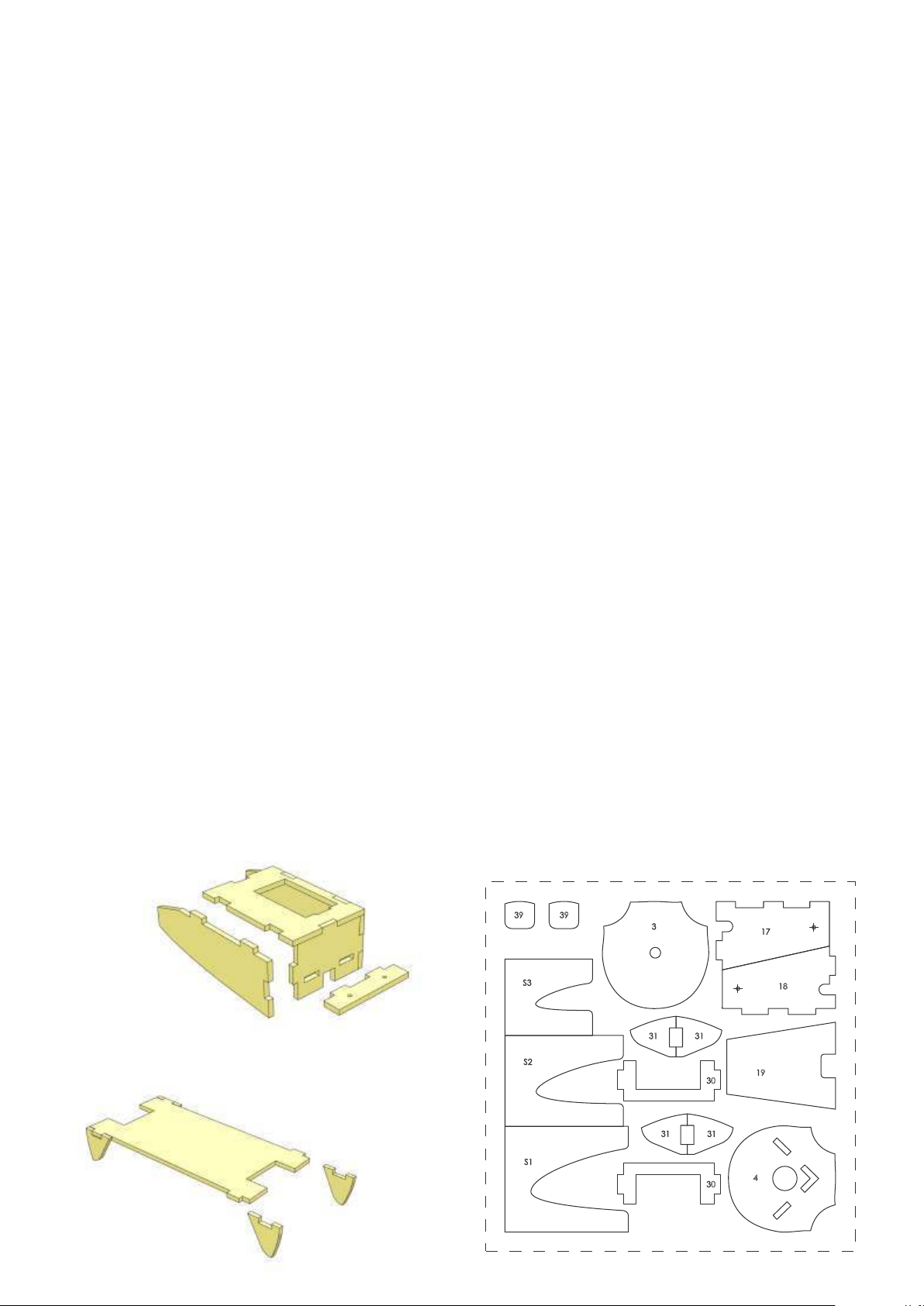
Detail drawing A shows the plan view of the frame support on the fuselage, together with the cut-out for the support (39). Glue the two parts (39)
together, and drill the 2.5 mm Ø hole at an angle as shown. This will be enlarged to 3 mm Ø later.
Glue the canopy latch (40) to a piece of 3 mm plywood using Stabilit Express as shown in Detail A, and glue this assembly in the fuselage using thickened
resin. The latch (40) must be positioned in such a way that the support (39) disengages reliably. Open up the hole in part (39) gradually and lock it in place
on the fuselage. Align the cabin frame on the fuselage. Check the location of the joint relative to part (39), and sand back gradually until the frame is
located perfectly. Glue the parts together carefully, and tape the frame to the fuselage again.
Carefully cut out and trim the canopy, leaving it as long as possible at the rear. A balsa plane (razor plane) set to a fine cut works very well for trimming the
plastic. Hold the blade at an angle to the edge of the moulding for best results. There is a bulge in the joint area of the cabin frame, and this must be
removed if the frame and canopy are to fit well - see also the “cabin frame” detail drawing on the plan. Either trim it using a sharp file or scrape it back
using a stiff knife blade.
The frame should be painted before the canopy is glued to it, but take care not to paint the joint surface. Mask out the fuselage carefully to prevent it
sticking to the canopy. Place the cabin frame on the fuselage, align it carefully, and fix it temporarily to the fuselage. Use a good plastic cement for gluing
the canopy to the frame. The glued joint is extremely long, so work quickly to avoid the glue hardening prematurely. Place the canopy in position and
tape it securely to the fuselage.
The method of assembling the cockpit fittings is self-explanatory. The assembly should be fitted into the fuselage at an angle, then pushed back as far to
the rear as possible (mind the servos!); set it horizontal, then slide it forward.
This version of the SHK kit includes conventional built-up wings and tailplane. See detailed building instructions below.
The tailplane panels are fixed to their pivot rods by means of grubscrews (55), which engage in the recesses in the tail panel retainers (7). Drill panles with
5 mm to accept the threaded sleeves (54). Glue in place with epoxy.
The counterbalance weights (58) are simply screwed into the sleeves (57) for flying, and can be removed for transport. Caution: the sleeve is only
threaded M2 at the end with the cross-hole. Seal the holes (including the end-hole) with thickened resin, roughen the sleeve and let it into the tail panel
tip. Carefully sand the panels overall and make sure that they move freely.
Attach the ailerons to the wings using hinge tape. If you wish to paint the GRP components, sand the surfaces carefully beforehand with 400-grit wet-
and-dry paper, used wet.
Recommended control throws for the maiden flight:
· Ailerons 12 mm up, approximately 4 mm down
· Elevator +/- 6-7 mm, 50 % Expo; for additional saftey use Dual Rate with increased travel.
· Rudder +/- 5-6 mm; you may find differential travel useful: a rudder command, e. g. left, causes the left panel to deflect 1 to 1.5 mm less than the
right panel. The optimum setting may be different for each individual pilot.
· Centre of gravity – 90 mm, as indicated on the plans.
We hope you will enjoy many hours of flying your new model. Happy landings!
Servo tray for tow release servo
Die-cut parts
Additional servo tray for V-tail servos
Page 5
Instructions for conventional built-up wings
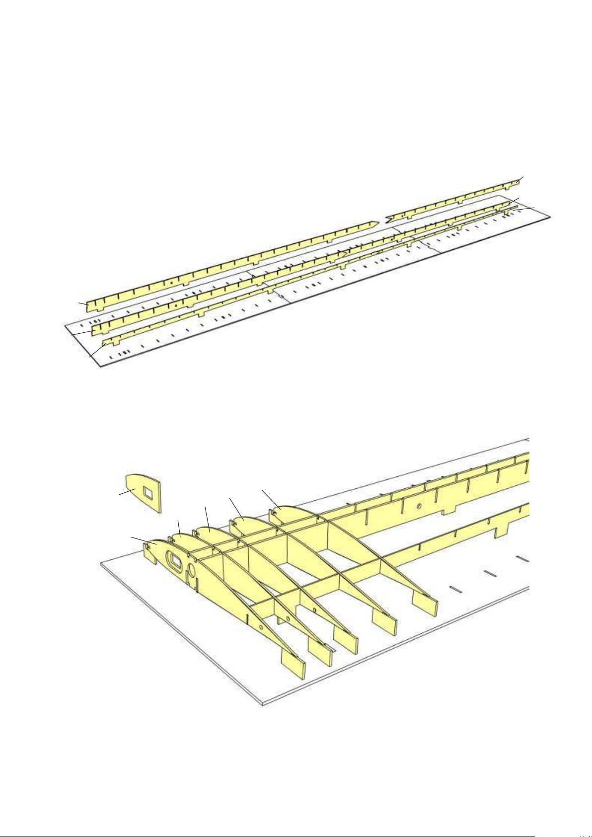
1
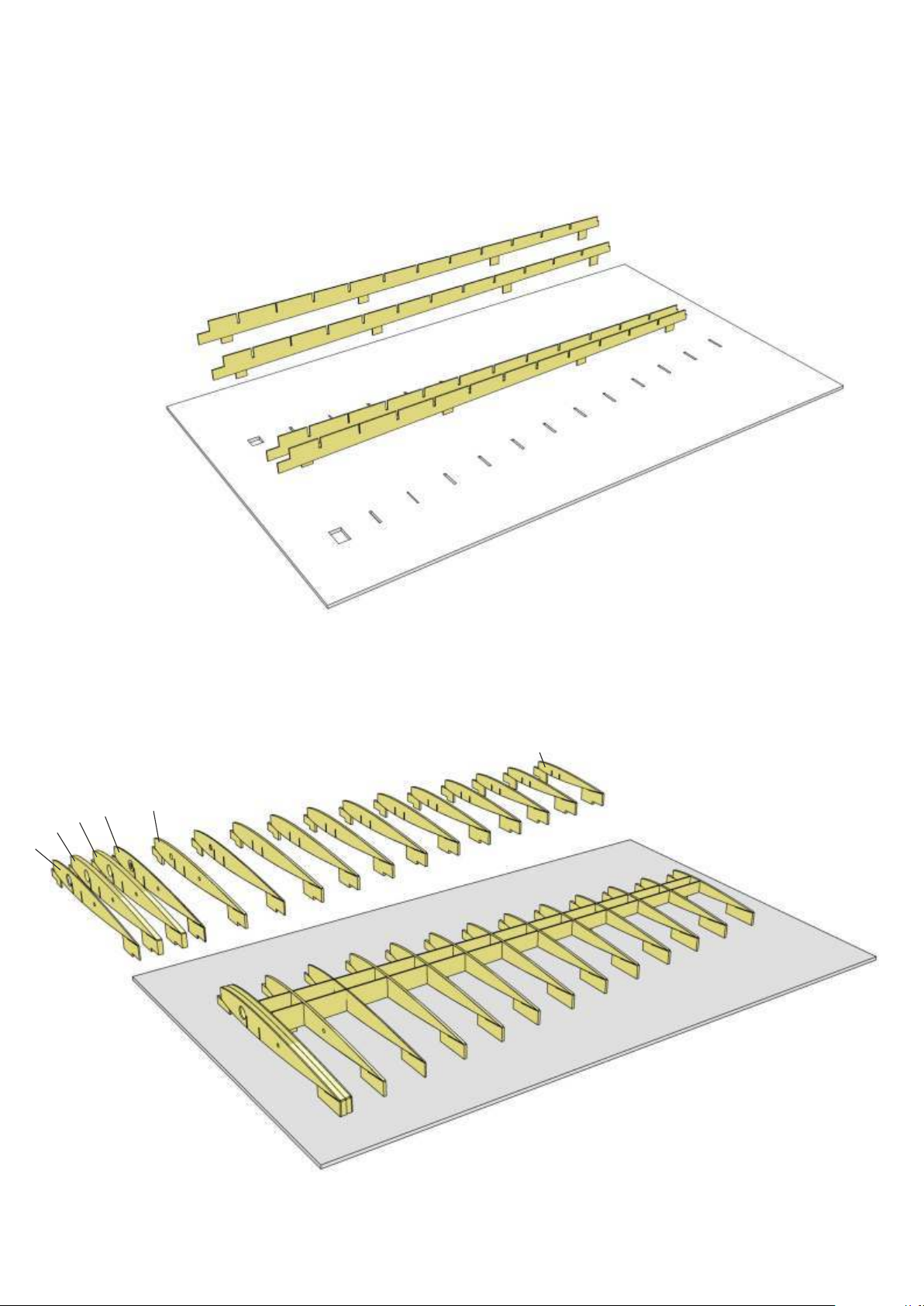
Remove any residue of the laser cutting process from ribs and spars. Arrange spar
components along a straight edge and glue together: front spar T 40 + T 40.1, centre spar T
41 + T 41.1, auxiliary spar T 42 + t 42.1.
Sand joints after glue has dried.
T 40
T 40.1
T 41.1
T 42.1
T 41
T 42
T 1.1
T 1
T 2
T 3
2
Assemble the three-part wing jig, secure with tape on building
board and insert spars into jig.
T 5
T 4
3
Glue T 1.1 to the inside of rib T 1.
Make sure ribs fit easily into spars and correct, if necessary. Then
glue ribs T 1 to T 5 in place.
Please note: Rib 1 is slightly angled due to wing dihedral. Glue
in place and secure to spars with tape.
Page 6
4
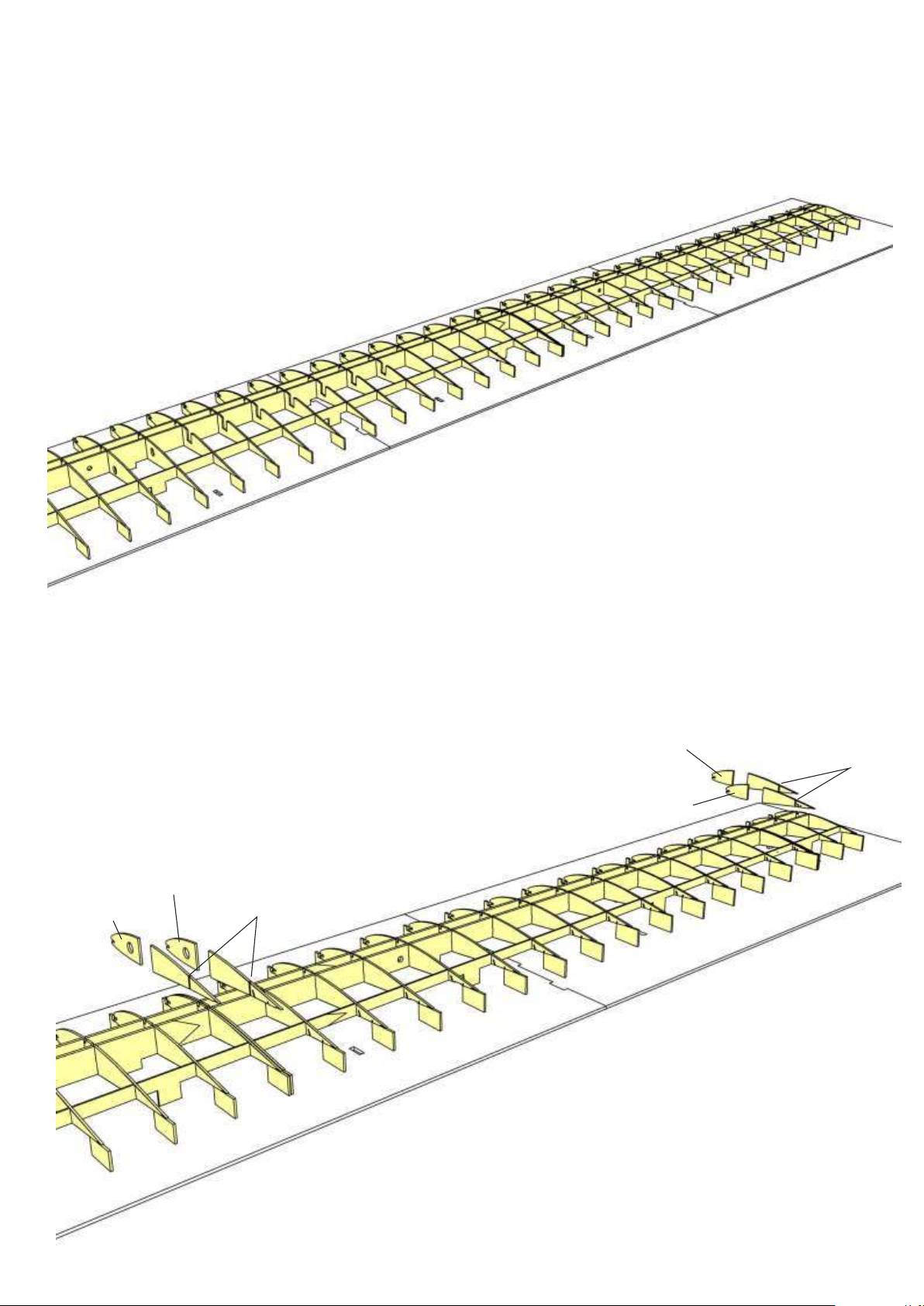
Make sure ribs fit easily into spars and correct, if necessary. Then
glue ribs T 6 to T 39 in place.
T 21.1
5
Cut off rear portions of doublers T 21.1 and T 22.1 as indicated, then glue doublers to ribs
T 21 and T 22.
Glue doublers T 36.1 and T 37.1 to ribs T 36 and T 37 accordingly.
T 37.1
cut off here
T 36.1
T 22.1
cut off here
Page 7
6
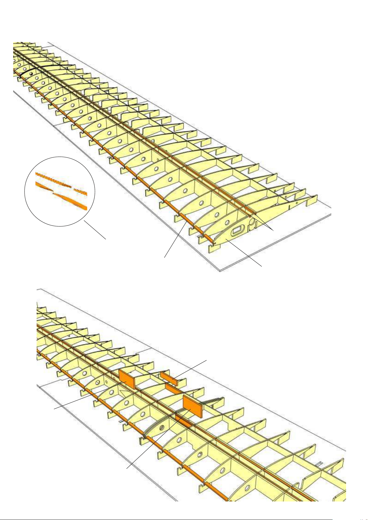
Splice together upper stringers T 43 (3×3 mm spruce) and leading edge
reinforcement T 44 (5×2 mm spruce) over a length of at least 3 cm. Glue
stringers to ribs and spars with special attention to splice. Secure with
clamps. Insert T 44 into front of ribs, secure splice with a clamp.
Note: Make sure rib T 1 remains straight after
T 44 is glued in place!
T 43
T 45
Splice over a length of at least 3 cm
T 44
T 1
7
Glue reinforcements T 45 and T 46 to the inside of main spars beneath
T 43 to reinforce spar joints.
Glue reinforcement T 47 to the front rear spar.
Note: Reinforcements are not rectangular but follow the taper of the
spars. First check correct orientation, then glue.
T 47
T 46
Page 8
T 48.1
8
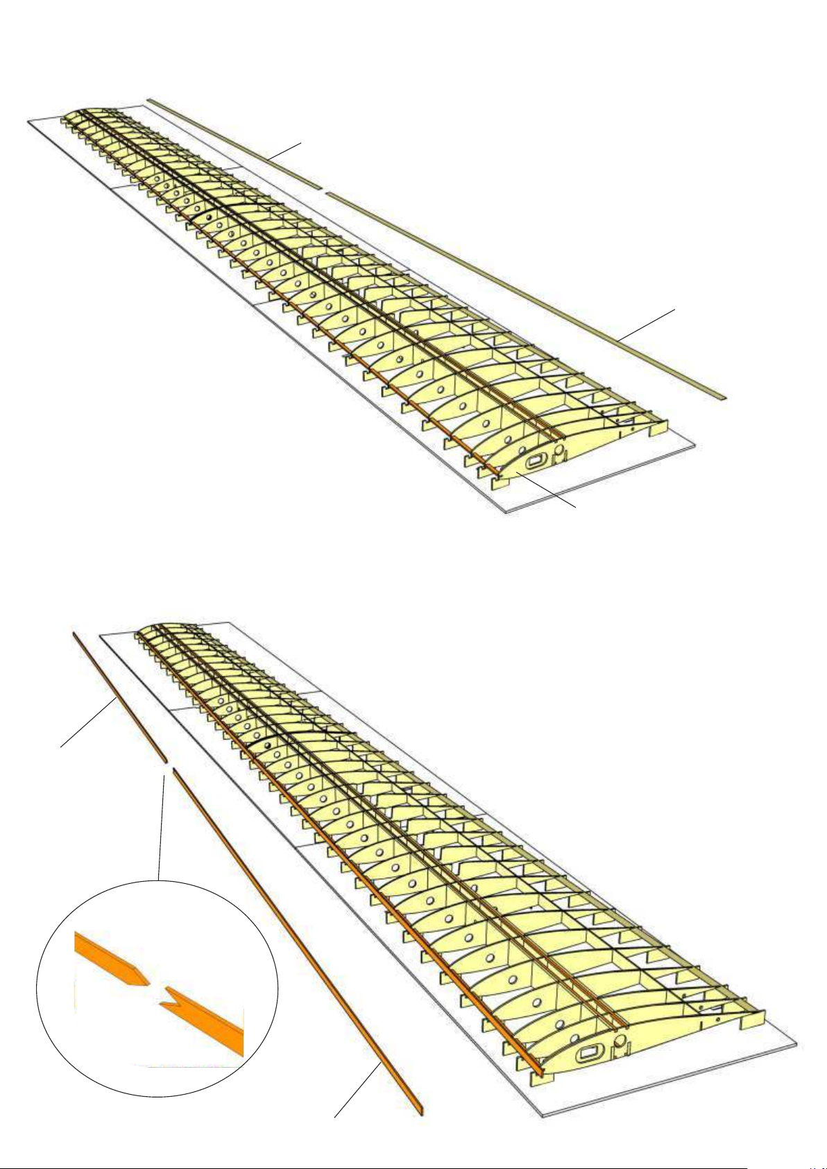
Insert auxiliary trailing edge T 48 + T 48.1 (0.8 mm birch ply) into slot
above building tabs and glue to ribs. Joint of T 48/T 48.1 is located at the
inboard end of aileron between ribs T 21 and T 22.
Note: Make sure rib T 1 remains straight after auxiliary trailing edge is
glued in place!
T 48
T 1
T 49.1
9
Arrange false leading edge parts T 49 + T 49.1 as well as leading edge parts T 50
+ T 50.1, T 51 + T 51.1 along a straight edge and glue together.
Glue false leading edge T49/T49.1 to front of ribs. Make sure false leading edge
is in good contact with top of building tabs.
Hold false leading edge in place by inserting (but don´t glue!) leading edge parts
T 50/50.1 and T 51/51.1 until glue has dried.
T 49
Page 9
10
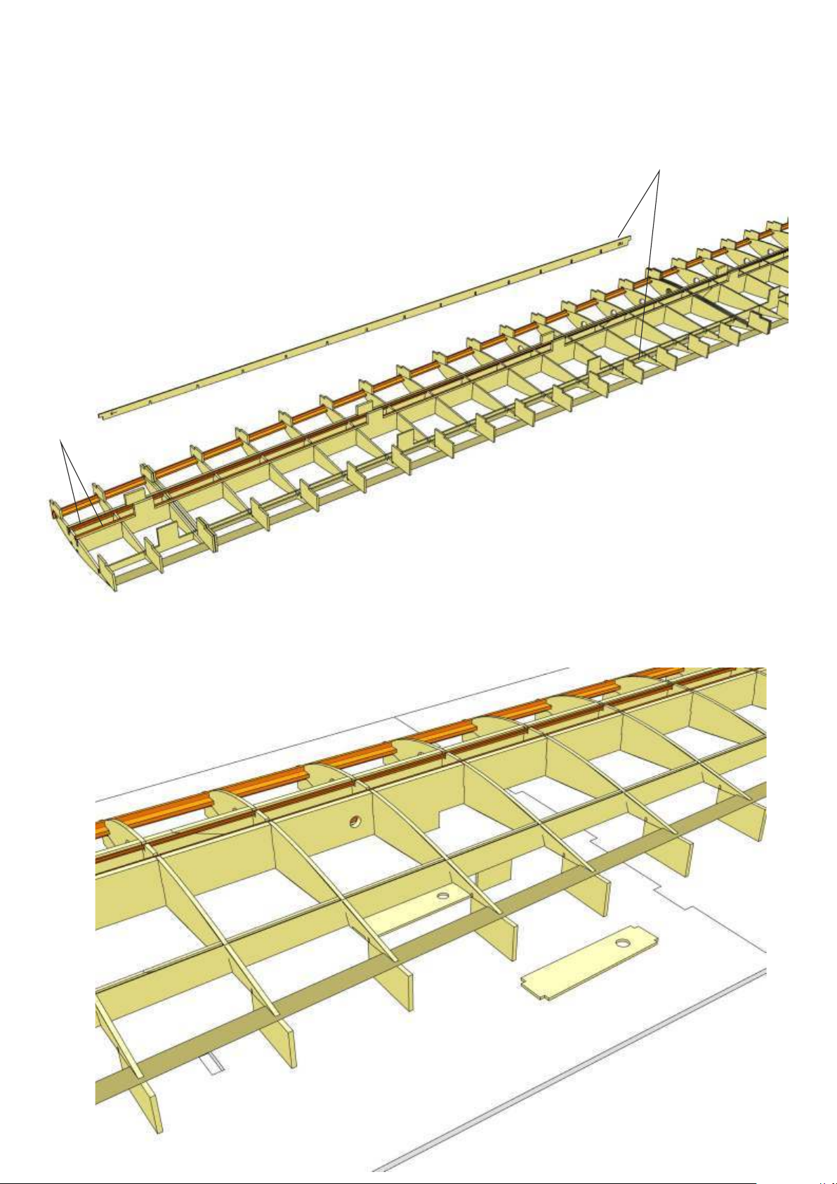
When glue has dried, carefully remove wing from jig. Splice together
lower stringers T 43 (3×3 mm spruce) and glue in place. Also glue in place
aileron leading edge T 52.
Note: The arrow on leading edge faces towards wing tip!
Put wing back into jig.
T 43
T 52
11
Slightly bevel front edge of control horn support T 53 and glue in place
between ribs T 25 and T 26. Please note that hole in T 53 faces wing tip.
T 26
T 25
T 53
T 53
Page 10
12
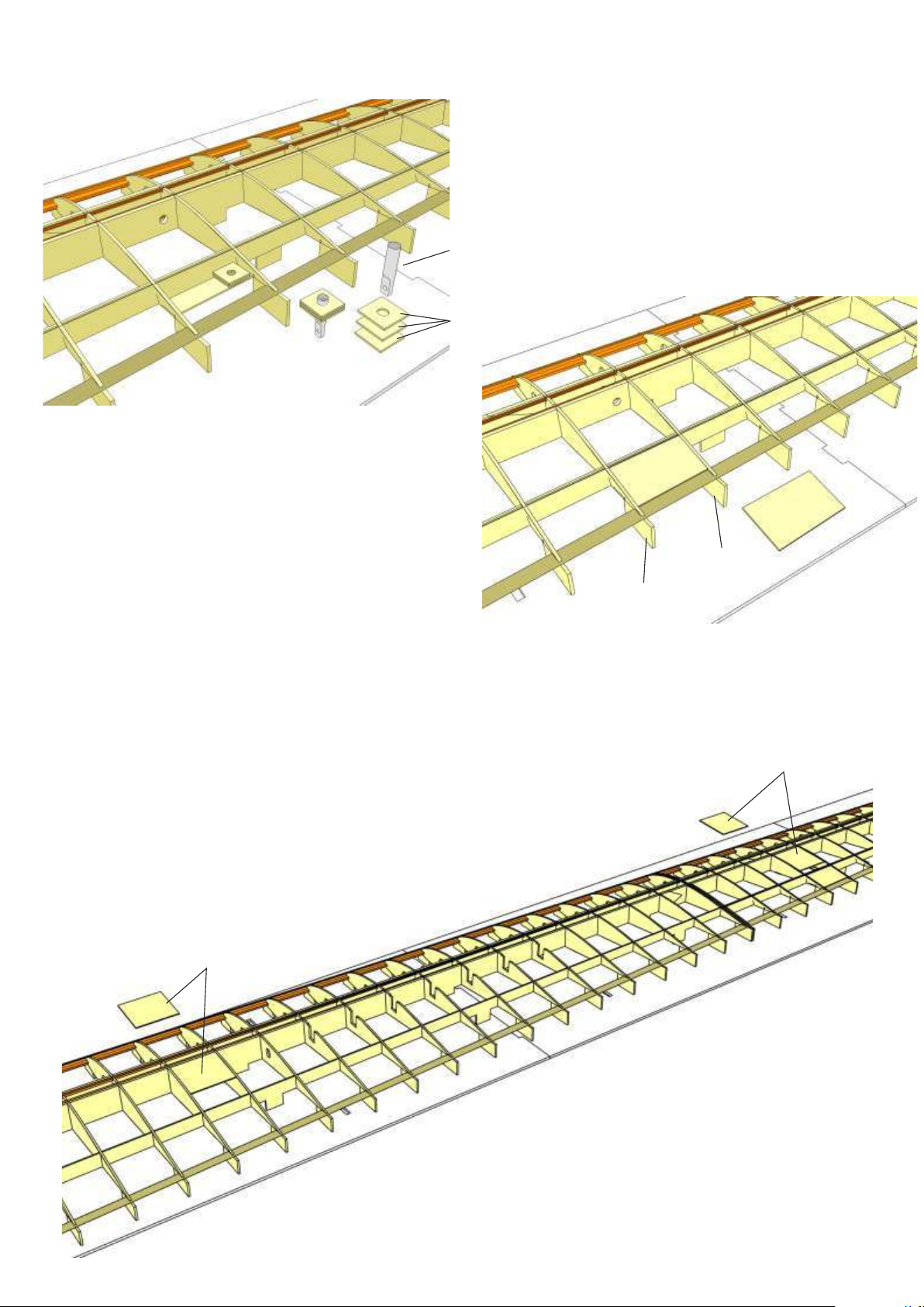
Glue together 3 control horn supports T 54, slide over control horn 49 and
leave to dry.
When dry, bevel front side of supports to fit angle of aileron leading edge.
Then glue supports to T 53.
Note: Make sure holes in supports T 53 and T 54 are aligned.
49
T 54
T 55
13
Slightly bevel front edge of reinforcement T 55 and glue in place flush
with top of ribs T 25 and T 26.
14
Glue servo trays T 56 (between ribs T 7 and T 8) and T 57 (between ribs
T 24 and T 25) to back of spar T 41 and flush with top of ribs.
You can do that now or after top wing sheeting is glued in place.
T 56
T 55
T 26
T 25
T 57
Page 11
15
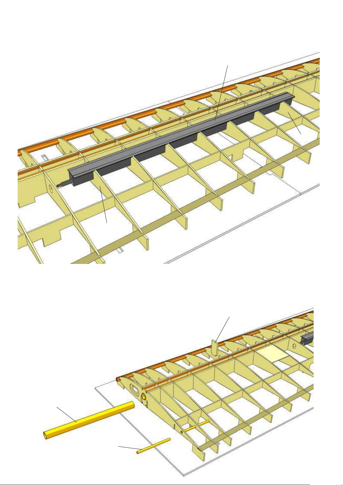
Use top wing sheeting as a guide to find correct position for spoiler. To do
this, remove cappping for spoiler from top wing sheeting T 61 and align
wing sheeting along contact surface of ribs T 21 and T 22.
Glue in place spoiler 47 in ribs T 10 to T 16, flush with upper rib contour
(5-min.-Epoxy).
47
T 16
T 10
16
Use epoxy to glue wing joiner sleeves T 58 and T 59 into root ribs.
Note: Sleeves must be flush with rib T 0 on completed wing. So
temporarily add rib T 0 to find correct position for sleeves. T 0 will be
glued in place after sheeting has been completed.
Glue T 60 to inside of sleeve T 58 as an end stop for wing joiner.
T 60
T 58
T 59
Page 12
17
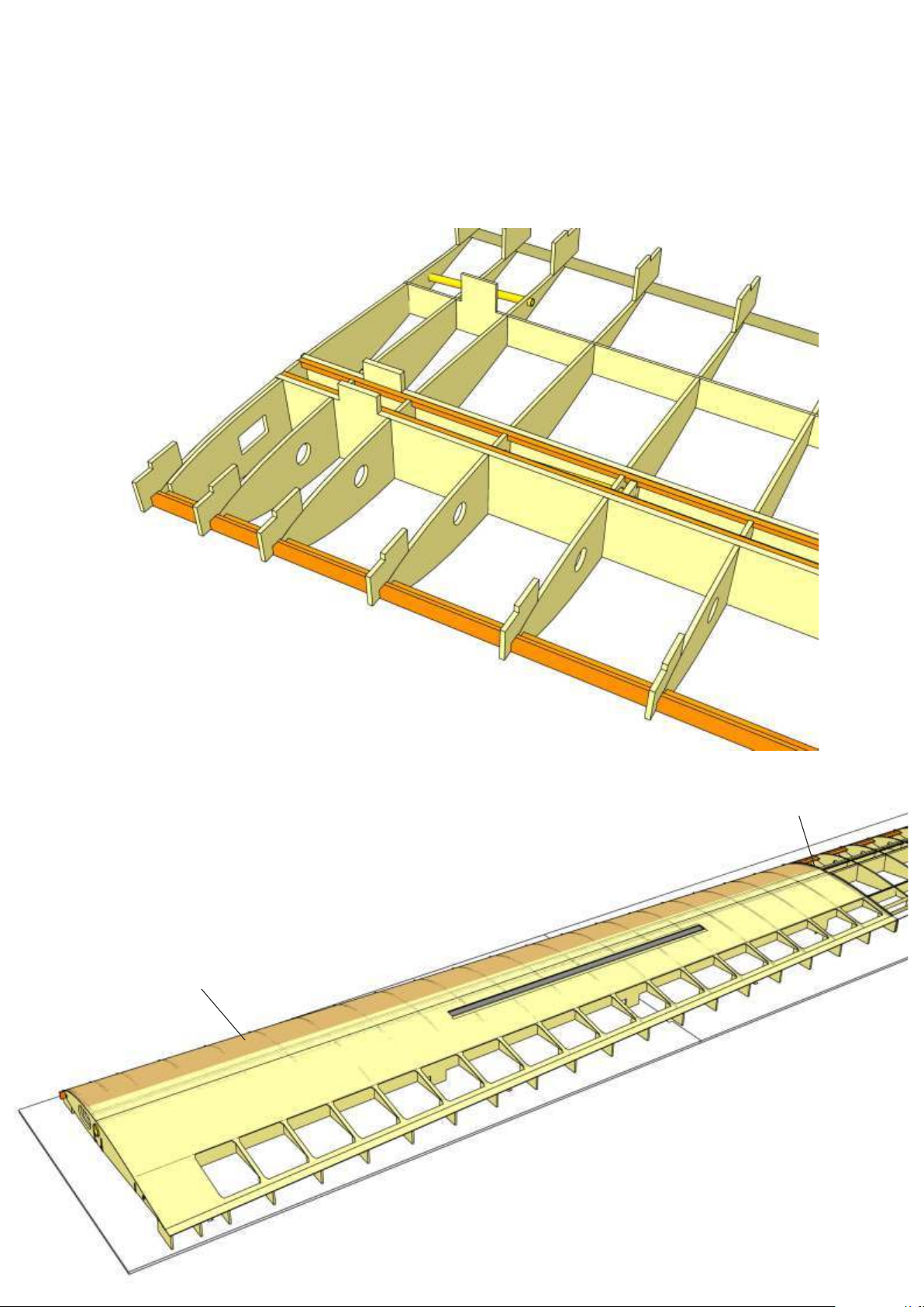
Sand top surface of spars around sleeve and seal with tape. Remove wing
from jig, turn upside down and fill in the space around sleeve between
ribs and spars with slow epoxy and chopped glas fibre strands.
Note: This can also be done after top wing sheeting has been glued in
place.
18
Insert wing in jig and carfully sand top surface of wing ribs and spars with
special attention to false leading edge, which must be flush with front of
ribs.
Position inner wing sheeting T 61 on wing and precisely align with
contact surface of ribs T 21 and T 22 as well as spoiler position.
T 61
Align sheeting material
Page 13
19
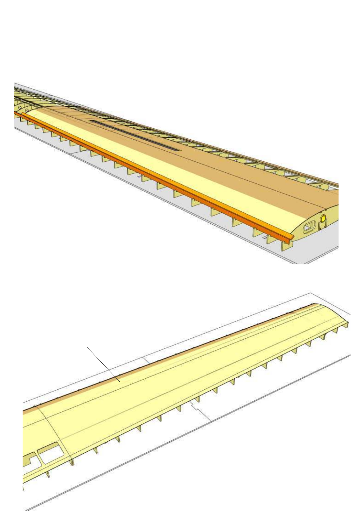
Secure sheeting material with tape at both ends, apply glue to false
leading edge and first 10 mm of each rib, position suitable stripwood over
front edge of sheeting material and press sheeting material against false
leading edge and ribs with clamps and tape.
When dry, glue top sheeting to ribs, spars and false trailing edge. Again
use suitable stripwood to hold down sheeting material, especially over
spars.
20
Apply outer wing sheeting T 61.1 accordingly with special attention to
aileron position.
Note: To position the sheeting material more accurately, you can remove
the aileron top sheeting from the sheeting material and add this at a later
stage.
T 61.1
Page 14
21
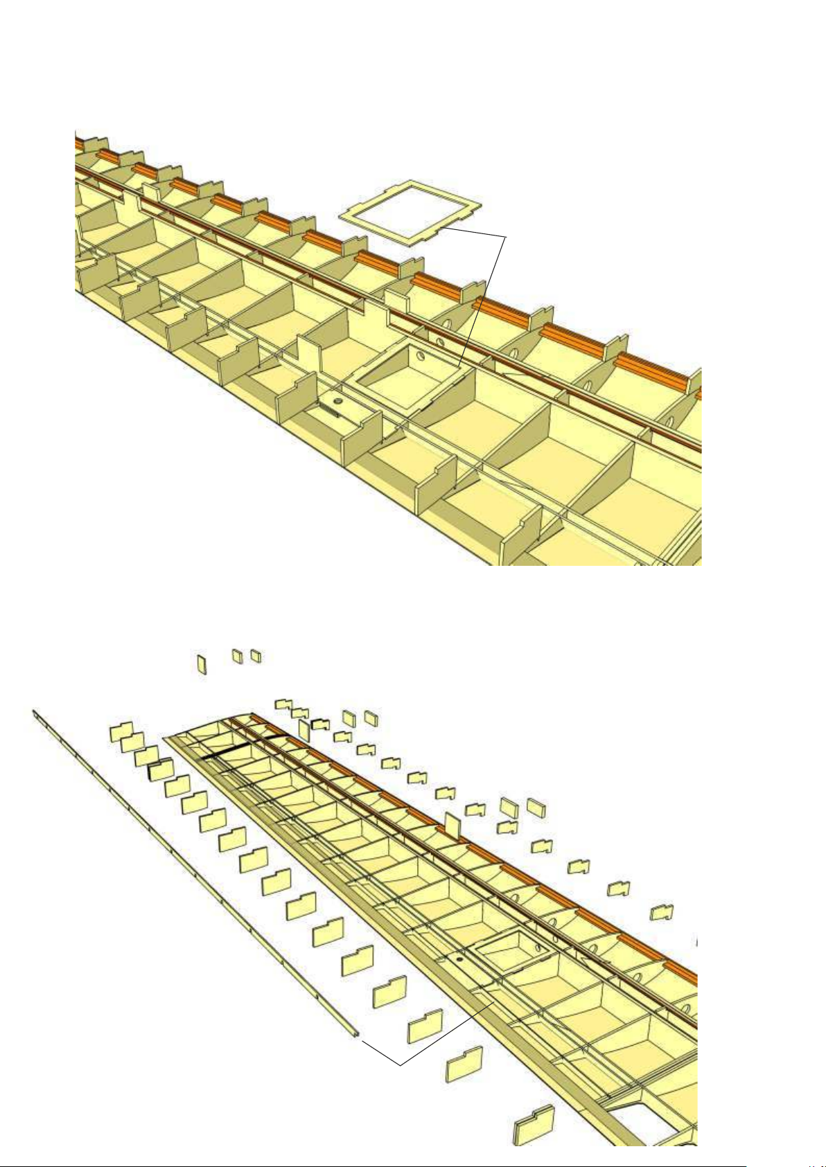
Remove wing from jig and turn upside down. If not already done, glue in
place servo trays T 56 (between ribs 7 and 8) and T 57 (between ribs 24
and 25 ) (see instructions above).
22
Glue in servo tray T 63 and mark position of aileron control horn in
top sheeting.
When wing sheeting is complete, a hole for the control horn can
be drilled through top sheeting.
T 63
23
Cut off building tabs from spars and ribs with a razor saw and
carefully sand ribs and spars.
Glue in place aileron spar T 64.
Note: Arrow on spar faces wing tip.
T 64
Page 15
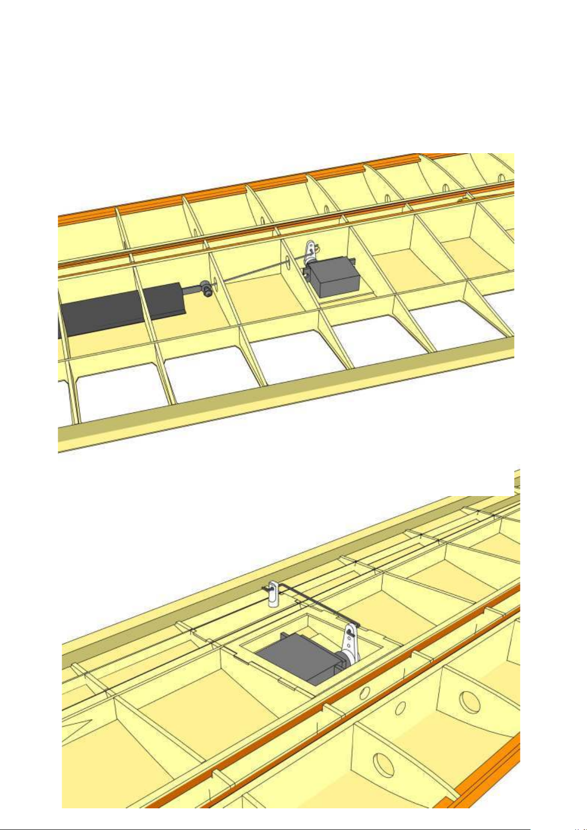
24
Install servos and servo leads.
Install spoiler pushrod as shown and check proper function. Pushrod must
move freely and without binding.
25
Temporarily install aileron pushrod to determine correct servo position.
Then remove pushrod and control horn.
Page 16
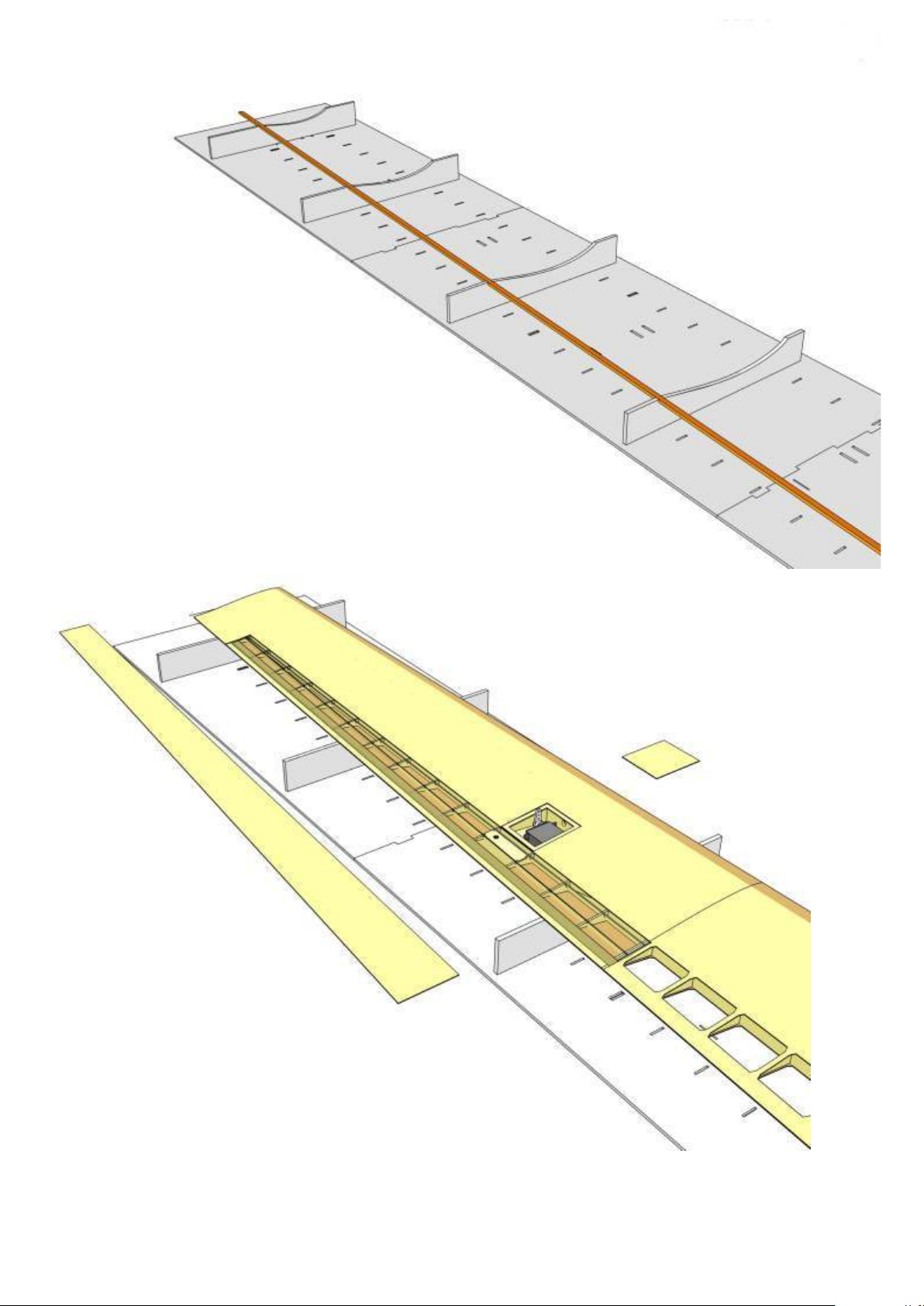
26
To apply bottom wing sheeting, turn jig upside down, insert 6 wing
templates (6 mm Depron) in jig and secure with tape.
Insert 3×8 mm spruce strips in templates as shown.
Use spruce strips to evenly spread hold-down pressure on sheeting
material when bottom wing sheeting is applied.
T 62.1
27
Carfeully sand underside of wing, then put wing back on jig upside down.
Position wing inner sheeting T 62 on wing and precisely align with
contact surface of ribs T 21 and T 22 as well as spar T 42. Glue in place as
described above. Apply outer wing sheeting T 62.1 accordingly.
Note: To position the sheeting material more accurately, you can remove
the aileron bottom sheeting and servo cover from the sheeting material.
T 62
Page 17
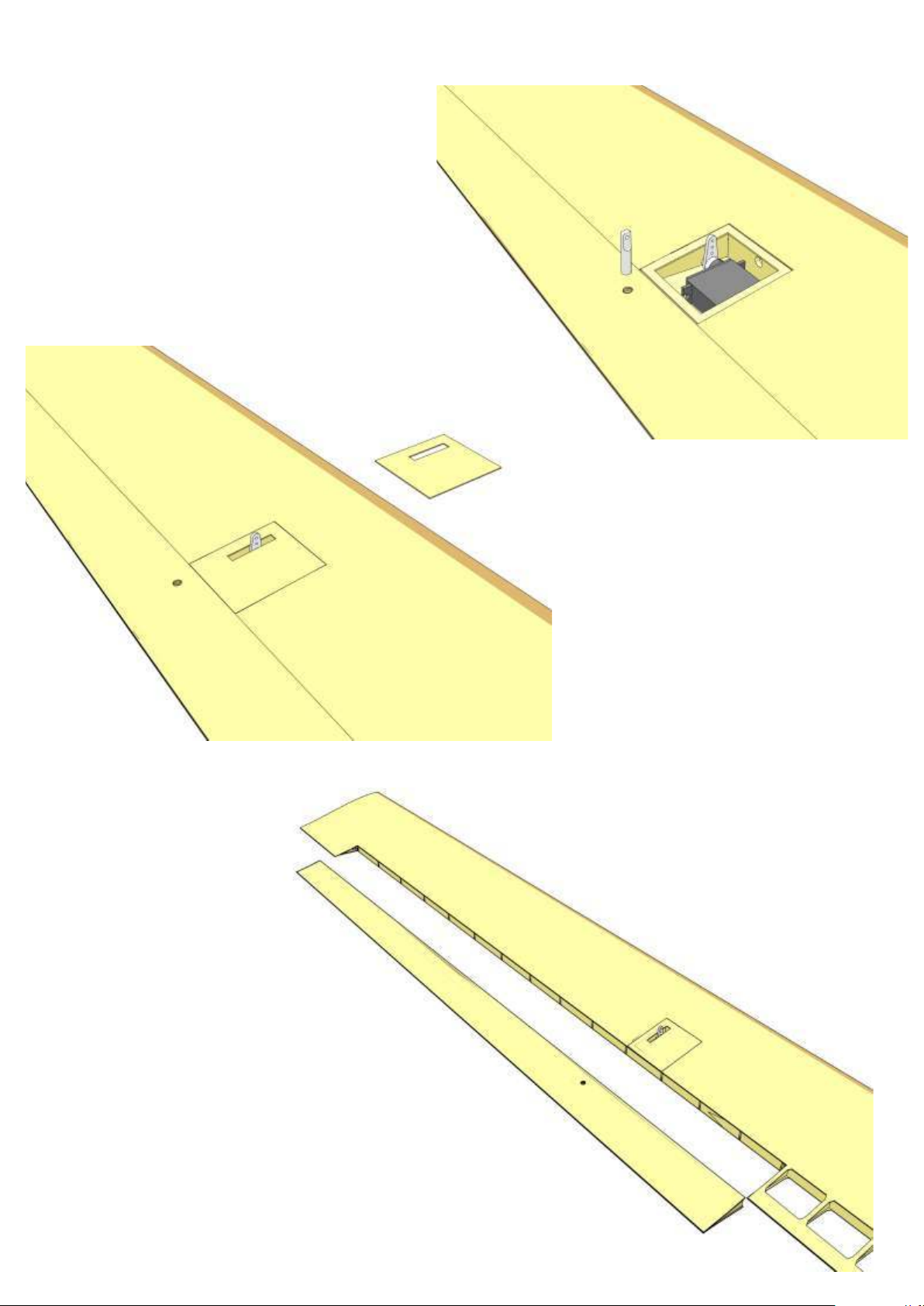
28
Remove wing from jig. Use mark on top sheeting to drill
hole for aileron control horn 49.
Cut control horn to suitable length (see construction
drawing) and bevel top side of control horn, so that control
horn is flush with sheeting material when installled.
29
Cut slot for control horn in servo cover and
install cover.
30
Use a sharp balsa knife and a razor saw to cut
out the aileron. Then sand carefully.
Page 18
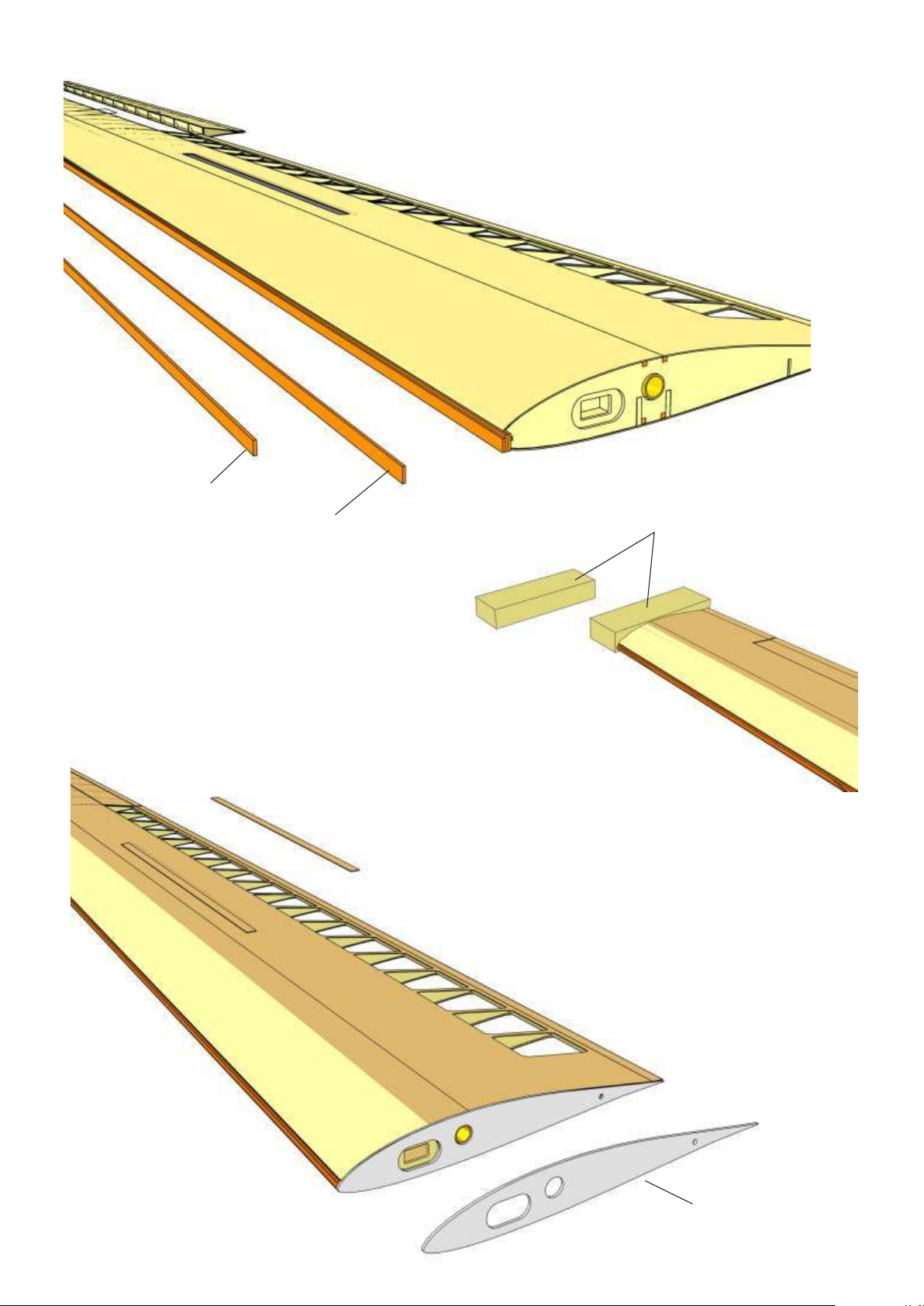
T 51/T 51.1
31
Sand sheeting material flush with front of false leading edge and glue
in place leading edge parts T 50 + T 50.1, T 51 + T 51.1 flush with
bottom wing sheeting material. Secure with tape until dry.
T 50/T 50.1
46
32
Cut off and sand sheeting material and stripwood at wing root and
tip.
Glue in place root rib T 0 and spoiler cover. Add wing tip 46. Carefully
sand and shape leading edge and wing tip. See section drawings for
correct shape.
T 0
Page 19
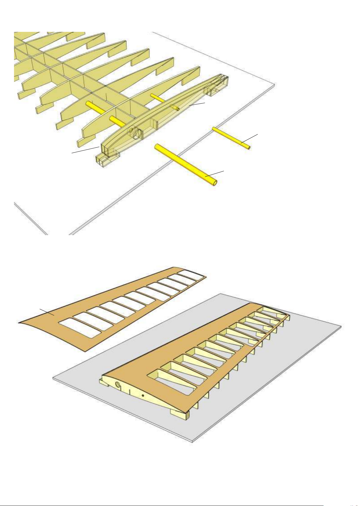
Tailplane
1
Place tailplane jig on a flat building board and secure with tape.
Insert front and rear spars L 17 and L 18, respectively.
L 17
L 18
2
Glue together ribs L 1, L 2, L 3 and L 4 and glue assembly in place
on spars. Make sure, that holes in ribs are not obstructed by glue.
Glue in place ribs L 5 to L 16.
L 5
L 1
L 2
L 3
L 4
L 17
L 18
L 16
Page 20
L 4
L 1
L 20
L 19
3
Insert sleeves L 19 and L 20 in ribs and glue with epoxy.
Note: L 19 must be flush with rib L 4, while L 20 protrudes 1 mm
from rib L 1.
L 20 will be flush with root rib L 0 when glued in place.
L 21
4
Carefully sand top surface of ribs and spars. Then apply top
sheeting L 21. Use stripwood and tape to hold down sheeting
material until glue has dried.
Page 21
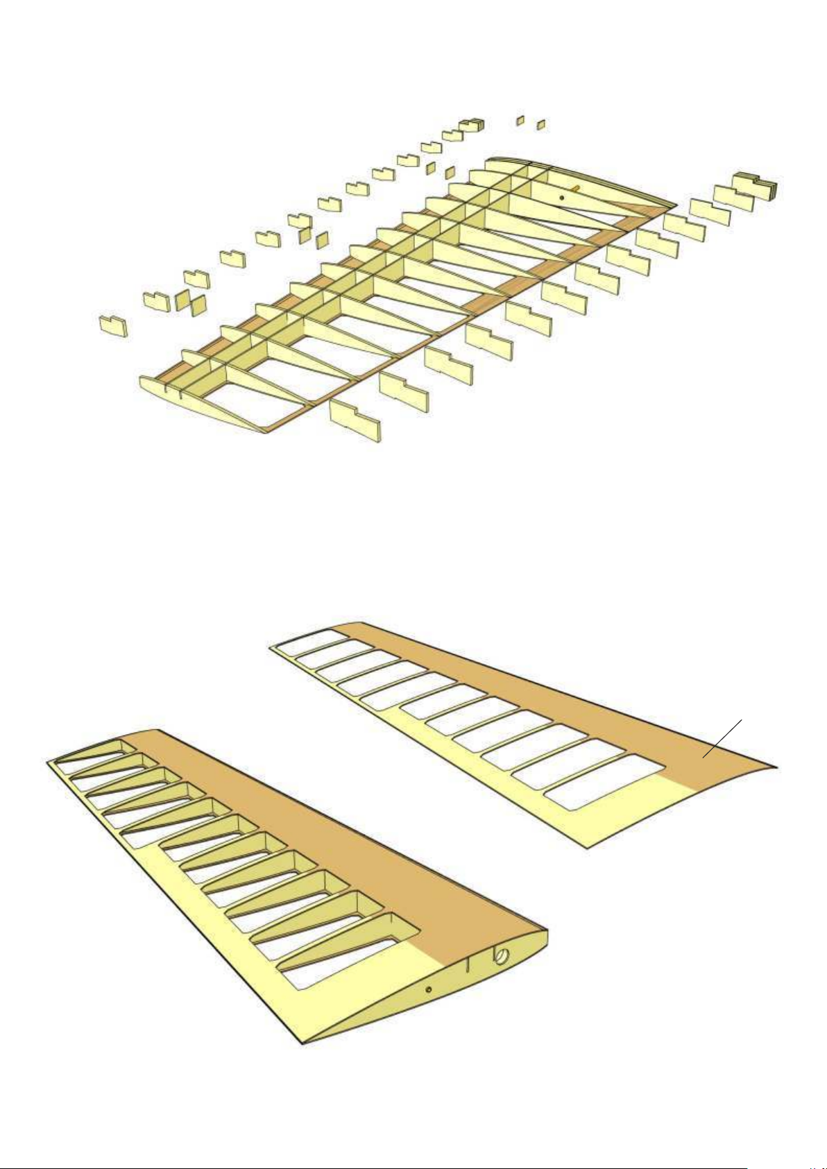
5
Remove tailplane from jig, cut off building tabs with a
razor saw and carefully sand.
6
Glue in place bottom sheeting L 22 and secure with tape
until dry.
L 22
Page 22
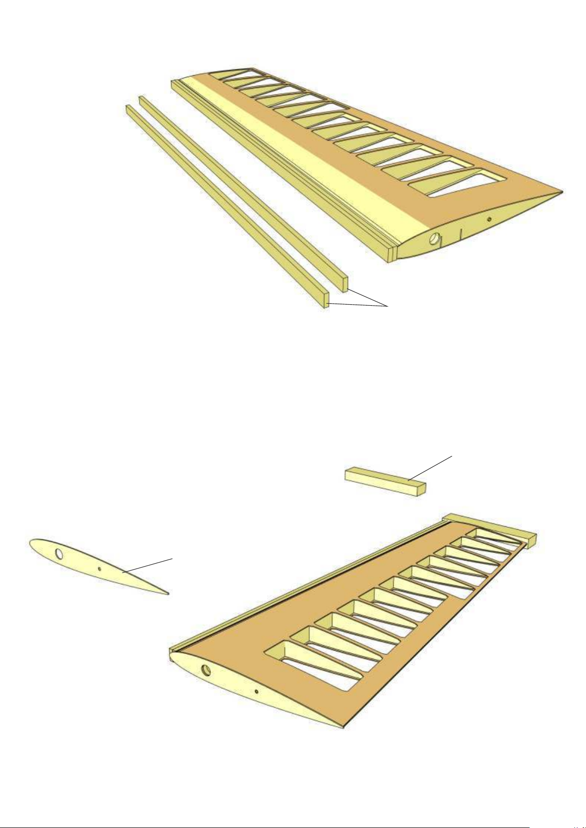
7
Sand sheeting material flush with front edge
of ribs and glue both leading edge parts L 23
to ribs and sheeting.
8
Carefully sand root and end rib, then glue in place
tailplane tip L 24 and root rib L 0.
L 23
L 24
L 0
Page 23
9
Sand and shape leading edge and tip as shown on
construction drawing.
10
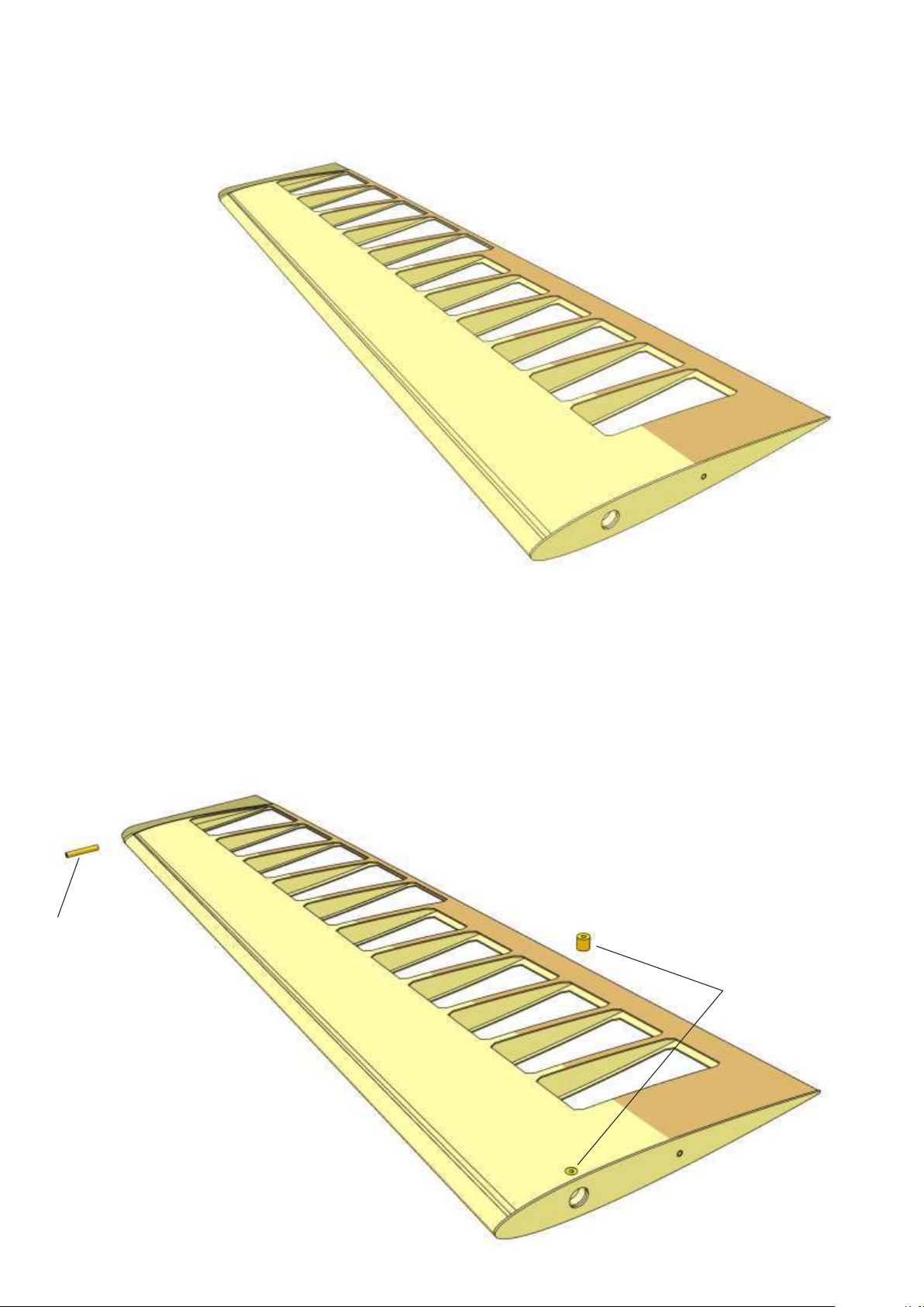
Drill holes for theaded sleeve 54 (V-tail lock) and 57 (tailplane
counterbalance) in sheeting and tip, respectively, and glue sleeves in
place. See also SHK construction drawings and general instructions.
57
54
Page 24
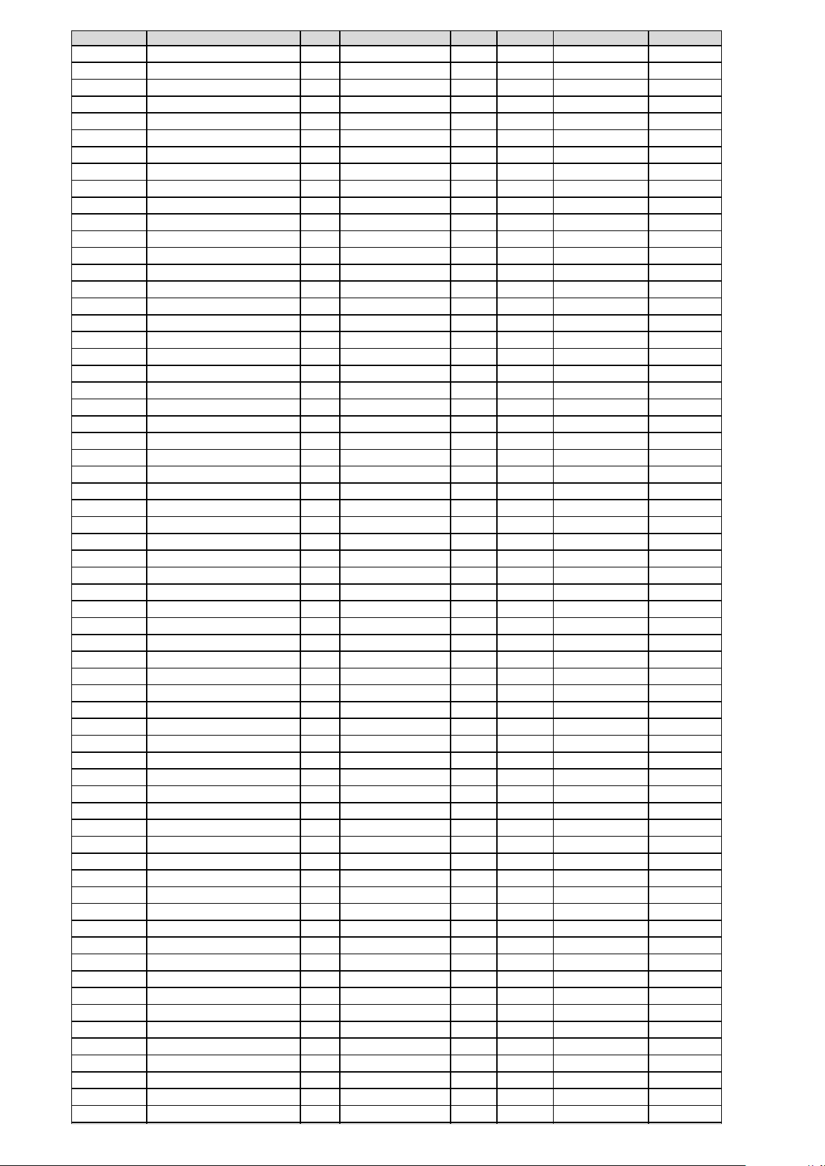
No.DescriptionPcs.MaterialSheetTypeDimensionsOrder No.
1fuselage1GRPhardware1125/02
2skid1limecut part10×10×10 mm
3former1plywooddie cut3 mm
4former1plywooddie cut3 mm
5tail pivot support1aluminiumhardware
6tail pivot rod2steelcut partØ4×98 mm
7tailplane retainer2aluminiumhardware
8captive nut1ironhardwareM37766/33
9screw1ironhardwareM3×20 mm7775/20
10spacer1brasscut partØ4/3×98 mm
11washer1brasshardwareØ9/4.3 mm7780/09
12washer9brasshardwareØ7/3.2 mm7780/08
13teilwheel leg1steelhardware7758/23
14tailwheel1aluminium / rubberhardware7761/22
15countersunk screw2ironhardwareM3×30 mm
16nut2ironhardwareM37774/03
17outrigger1plywooddie cut3mm
18outrigger1plywooddie cut3mm
19base plate1plywooddie cut3mm
20beelcrank1+1aluminiumhardware
21tailskid support1plywoodcut part5×10×40 mm
22plate1aluminiumcut part2×8×20 mm
23self-tapping screw1steelhardwareØ2,9×16 mm
24fuselage tail cap1GRPhardware1125/03
25snake outer3plasticcut partØ3mm
26V-tail actuator2GRPcut partØ2 × 1000 mmm
27threaded coupler, plain4iron, chrome platedhardwareM2
28nut6brasshardwareM27773/02
29clevis6steel, chrome platedhardwareM27489/01
30servo tray2plywooddie cut3 mm
31servo tray support4plywooddie cut3 mm
32dowel1beechwoodcut partØ8mm
33wing joiner sleeve, fuselage1brasscut partØ14/12×148 mm
34cockpit floor1plastichardware
35backrest1plastichardware
36instrument panel1plastichardware
37cabin frame1plastichardware
38dowel1beechwodcut partØ3 × 48 mm
39support2plywooddie cut3 mm
40canoopy latch1brass / steelhardware7329/00
41canopy1plastichardware1125/04
43wing joiiner sleeve2brasscut partØ14/12×165 mm
44wing joiner rod1steelcut partØ12 mm
45incidence peg2piano wirecut partØ4×50 mm
46wingtip2balsacut part147×45×22 mm
47spoiler2aluminium / plastichardware7329/46
49aileron horn2aluminiumhardware7491/05
50threaded rod6galvanized ironhardware7488/04
51clevis2plastichardware7489/04
52wing retainer1steel / plastichardware7329/55
54threaded sleeve2brasshardwareØ4×50 mm
55grubscrew2steelcut partM3×4 mm 7784/01
56pin2steelcut partØ2 × 20 mm
57control horn2steel, chrome platedhardware7491/06
58tailplane counterbalance2brasshardwareØ4×50 mm
61self-tapping screw8steel, chrome platedhardware2,2×6.5 mm7768/21
S1-S3airfoil templateplywooddie cut3 mm
T-0root rib2birch plywood1laser cut2 mm
T-1 - T-5ribje 2birch plywood1laser cut2 mm
T-1.1doubler2birch plywood1laser cut2 mm
T-6 - T-39ribje 2obechi2+3laser cut2 mm
T-21.1doubler for rib 212obechi2laser cut2 mm
T-22.1doubler for rib 222obechi2laser cut2 mm
T-36.1doubler for rib 362obechi3laser cut2 mm
Page 25
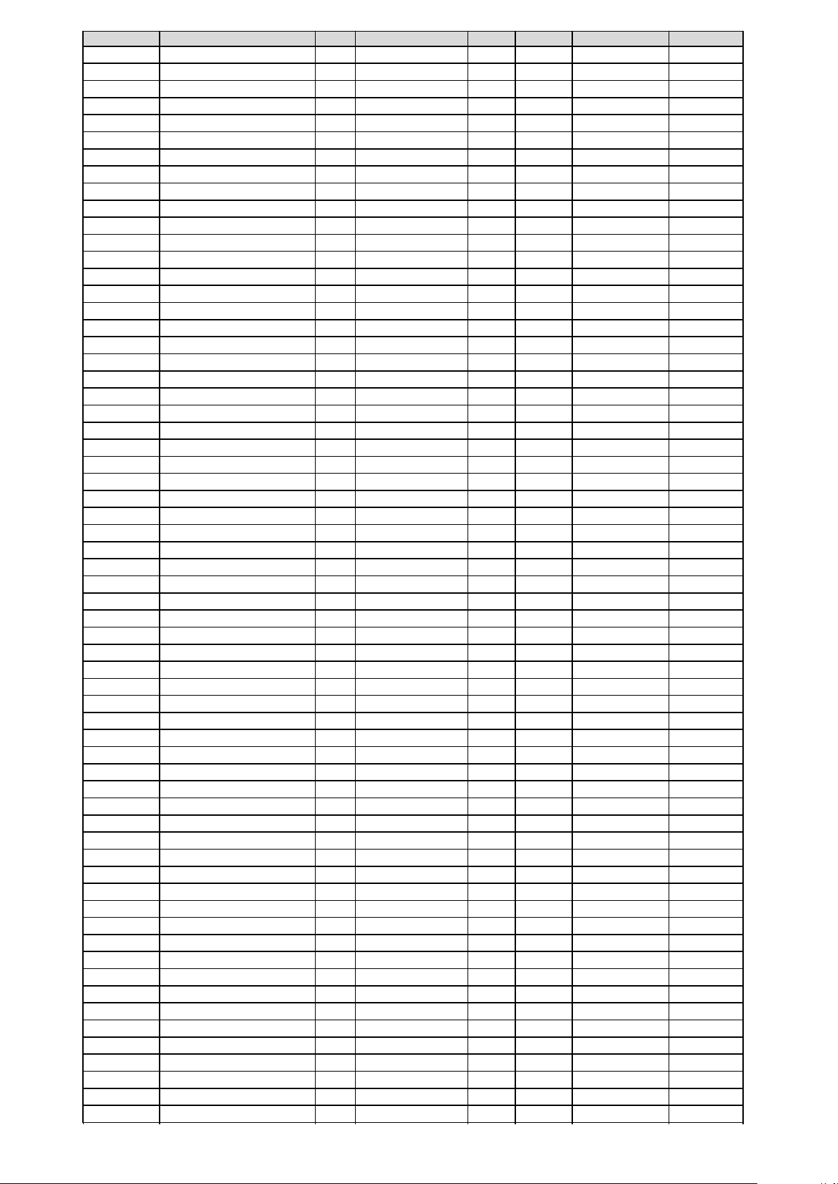
No.DescriptionPcs.MaterialSheetTypeDimensionsOrder-No.
T-37.1doubler for rib 372obechi3laser cut2 mm
T-40spar, front inner2birch plywood5laser cut3 mm
T-40.1spar, front outer2birch plywood5laser cut3 mm
T-41spar, mid inner2birch plywood5laser cut3 mm
T-41.1spar, mid outer2birch plywood5laser cut3 mm
T-42spar, rear inner2birch plywood6laser cut1.5 mm
T-42.1spar, rear outer2birch plywood6laser cut1.5 mm
T-43stringer16sprucecut part3×3×1000 mm
T-44false leading edge4sprucecut part5×2×1000 mm
T-45reinforcement2birch plywood5laser cut3 mm
T-46reinforcement2birch plywood5laser cut3 mm
T-47reinforcement2birch plywood6laser cut1.5 mm
T-48false trailing edge2birch plywood11laser cut0.8 mm
T-48.1false trailing edge2birch plywood11laser cut0.8 mm
T-49false leading edge, inner2obechi7laser cut1.5 mm
T-49.1false leading edge, outer2obechi7laser cut1.5 mm
T-50leading edge, inner2obechi7laser cut1.5 mm
T-50.1leading edge, outer2obechi7laser cut1.5 mm
T-51leading edge, inner2obechi7laser cut1.5 mm
T-51.1leading edge, outer2obechi7laser cut1.5 mm
T-52aileron leading edge2birch plywood8laser cut1 mm
T-53aileron horn support2birch plywood4laser cut1 mm
T-54aileron horn support6birch plywood4laser cut1 mm
T-55reinforcement2birch plywood4laser cut1 mm
T-56servo tray2birch plywood4laser cut1 mm
T-57servo tray2birch plywood4laser cut1 mm
T-58wing joiner sleeve2brasscut part14/12×165 mm
T-59wing joiner sleeve2brasscut part4/3×65 mm
T-60sleeve end stop 2birch plywood5laser cut3 mm
T-61top sheeting, inner L/R2A-Tex12+13laser cut0.7 mm
T-61.1top sheeting, outer L/R2A-Tex12+13laser cut0.7 mm
T-62bottom sheeting, inner L/R2A-Tex14+15laser cut0.7 mm
T-62.1bottom sheeting, outer L/R2A-Tex14+15laser cut0.7 mm
T-63frame, servo well2birch plywood4laser cut1 mm
T-64aileron spar2birch plywood8laser cut1 mm
L-0root rib2birch plywood8laser cut1 mm
L-1rib1birch plywood8laser cut1 mm
L-2, L-3ribje 2balsa10laser cut4 mm
L-4rib2birch plywood8laser cut1 mm
L-5rib2balsa9laser cut2 mm
L-6rib2birch plywood8laser cut1 mm
L-7 - L-16ribje 2balsa9laser cut2 mm
L-17taiplane spar, front2birch plywood8laser cut1 mm
L-18tailplane spar, rear2birch plywood8laser cut1 mm
L-19sleeve2brasscut part5/4×65 mm
L-20sleeve2brasscut part3/2×40 mm
L-21top sheeting L/R2A-Tex16laser cut0.7 mm
L-22bottom sheeting L/R2A-Tex16laser cut0.7 mm
L-23leading edge4balsa10laser cut4 mm
L-24tailplane tip2balsacut part110×20×12 mm
A-0servo tray1birch plywood18laser cut3 mm
A-1servo tray, front support2birch plywood18laser cut3 mm
A-2servo tray, rear support2birch plywood18laser cut3 mm
A-3servo tray, tow release1birch plywood17laser cut3 mm
A-4servo tray, tow release2birch plywood17laser cut3 mm
A-5servo tray, tow release3birch plywood17laser cut3 mm
A-6servo tray, tow release1birch plywood17laser cut3 mm
A-7servo tray, tow release1birch plywood17laser cut3 mm
wing building jig3Depron0laser cut6 mm
tailplane building jig1Depron0laser cut6 mm
wing templates6Depron0laser cut6 mm
wing jig strip wood2sprucecut part3×8×1000 mm
decals1plastichardware
Page 26
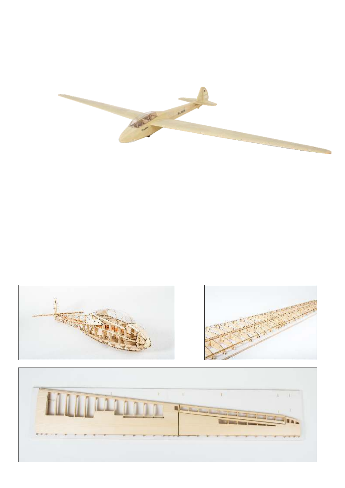
Did you enjoy building your model sailplane?
Then let us introduce another model from our range of historic sailplanes.
Mü-13e Bergfalke I
The Mü-13e (later
Bergfalke I) was designed
and built in 1951, at a time when
soaring was banned in Germany.
Egon Scheibe based the new design on the
pre-war sailplane Mü-13 of the Akademi-
sche Fliegergruppe München.
The model is a scale reproduction of the original.
You will like the all-wood construction of fuselage and wing, the innovative building jig, the precision of the laser-cut parts and the high
quality of selected wood.
The Bergfalke has a wing span of 3.5 meters and you will enjoy building as well as flying this model. The manouverable model will do well on
a flat field or on the slope.
The kit contains:
Laser-cut wood for fuselage and wing, innovative sheeting material A-Tex, canopy, complete hardware package including stripwood, hinges,
screws etc. and comprehensive illustrated building instructions.
Wingspan
Length
Flying weight
Wing airfoil
Radio
3,500 mm
1,600 mm
min. 3,900 g
HQ 3.5 Oldtimer
Rudder, elevator (V-tail), ailerons, spoilers, (tow release)
Page 27
Page 28
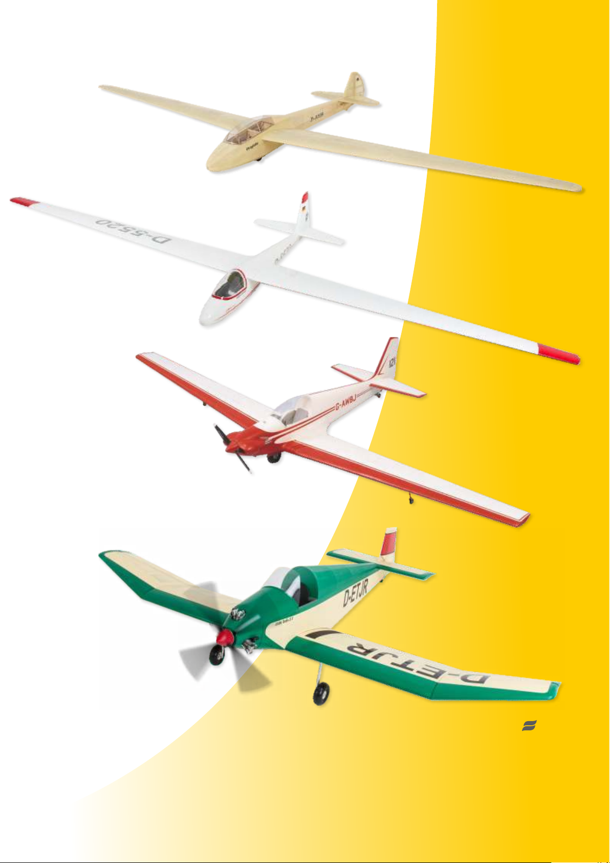
Some more models from our range ...
Mü13-E Bergfalke 1124/00
All-wood construction, laser-cut
parts.
Wingspan 3,500 mm
Ka 6-E 1127/00
Kit inculdes GRP fuselage and
parts for conventional wings.
Wingspan 3,600 mm
Fournier RF-4D 1355/00
Kit inculdes GRP fuselage,
foam wings and complete
hardware package.
Wingspan 2,815 mm
Jodel D.9 Bébé 1312/00
All-wood construction, laser-cut
parts.
Wingspan 2,400 mm
aero
naut
Find many more models at www.aero-naut.de
aero-naut Modellbau
Stuttgarter Strasse 18-22
D-72766 Reutlingen
www.aero-naut.de
1125/01 - E1 - 12/2016
 Loading...