

Page 1
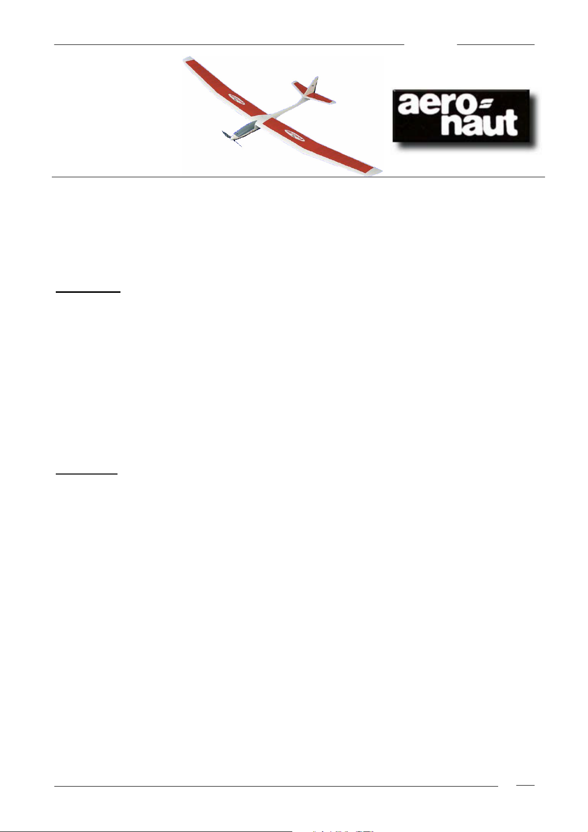
Powerfly
Building
Instructions
Powerfly
RC-Electric Glider
Order No. 1320/00
Specification:
Span c. 1935mm
Length c. 930mm
Wing area c. 30,98dm²
Elevator area c. 4,5dm²
Total surface area c. 35,48dm²
Airfoil SD 3021, 9,5% to 8%
Aspect ratio 12.08
Flying weight with 8 Sanyo 1000 SCR cells,
air brake and 2 x 9g-Servos) c. 1050g
Surface loading c. 33,9g/dm²
Total area load with a
take-off weight of 1050g c. 29,6g/dm²
RC functions:
Elevator,
rudder,
speed controller,
optional air brake-flaps.
„aero-naut“ Modellbau
Stuttgarterstr. 18-22 Tel. +49 (0) 7121 / 433 088-0
D-72766 Reutlingen Fax +49 (0) 7121 / 433 088-8
P.O.Box 1145
D-72701 Reutlingen http://www.aero-naut.com
© by „aero-naut“ Modellbau
Powerfly
1
Page 2

Powerfly
The Powerfly is a development from the Panafly 400 G. The reason for the introduction of Powerfly was
based particularly on the outstanding flight performance of its predecessor. Newer motors, gearboxes and
propellers, an epoxy glass fuselage, and 500 - 600 direct drive options, flight nicad access enabled by a
removable cockpit canopy, all of this makes "Powerfly" very practical and easy to fly. The fuselage was
extended by 15mm, the wing wing is unmodified. Almost completely without aerodynamic compromise - e.g.
the wing shaping. The Selig-Donovan SD3021 wing profile varies from 9,5% thick to 8% at the tip.
"Powerfly" is aerodynamically responsive with a low sink-rate, and good "floatability" for soaring in even
weak thermals. A low drag allows surprisingly high speeds without significant altitude loss. We recommend
air brake flap installation.
Drive combinations for 8 cells:
Race 400-7,2v with gearbox 1,66:1 7121/32 propeller 9,5x5 " 7234/26
or 1,86:1 7121/33
or 2,33:1 7121/35 10x6 " 7234/28
or 10,5x6 " 7234/35
or 10x7 " 7234/30
Race 400-6v with gearbox 2,33:1 7121/35 propeller 9,5x5 " 7234/26
or 2,64:1 7121/16 9,5x5 7234/26
or 10x6 " 7234/28
or 3,00:1 7121/17 propeller 10x6 " 7234/28
or 10x7 " 7234/30
or 10,5x6 " 7234/35
"480 " motors with adjustable back bearing plate are an excellent power selection. With the help of the 480adapter they may be built into our Aeronaut 400 " L"-gearbox. For these engines there are gear sets with a
pinion bored ø 3,17mm. L motor mount Part.Nr. 7120/96, gearbox case 7120/98, ball bearings ø 4mm
7821/41 and 7822/40 (1 each.), and 480-adapter 7120/90
Examples of drives with 8 cells:
Speed 480 BB Race 7,2v
with gearbox 3,0:1 7121/79 propeller 10x6 7234/28
AP 29 BB and Permax 400 BB
with gearbox 2,64:1 7121/78 propeller 10x6 " 7234/28
Still more efficient drives can be achieved with a higher reduction gearbox. Reisenauer planetary gears (from
3,5 to 5,0:1 Micro) would be suitable, a complete Kirchheim/Teck speed 480 - 3,45:1 unit,or the Simprop
CNC gearboxes of (3.4 to 5,9:1), or Plettenberg HP 200 / 20 4,4:1. The small Kontronik brushless drive set,
drive 200, represents the limit of feasible power systems! With reductions of 5,0:1 and higher, 10 cell flight
nicad packs - e.g. 10 x Sanyo 1400 AE nicad packs are suitable.
Examples of drives with 8 cells:
Speed 480 Race BB 7,2v and Kyosho AP 29 BB
with gearbox 4.0 to 4,5:1 propeller 12x7 " 7234/48
or 11x8 " 7234/42
Permax 400 BB with gearbox 4,0:1 propeller 12x7 " 7234/48
or 11x8 " 7234/42
Permax 450 turbo with gearbox 3,5:1 propeller 14x9 " 7234/67
High-speed 540 car/buggy motors may also be used, likewise standard Speed 500 and 600 with direct drive
- ie no gear reduction. Electronic speed controllers BEC (battery elimination circuit) should have at least 1A
supply of 5V. The electro motive force brake operation should delay at least 1 second until rpm adjusts!!
This extends life of both gearbox and the engine!
Powerfly
2
Page 3

Powerfly
If using a 400 motor adjust the bearing plate by rotating around 20-30° against engine direction of travel with
the help of the timing adjuster tool, Part.Nr. 7329/34. This corresponds - converted into linear measurement
- to from 5 to 7mm, based on the motor case backplate.
With a 480 motor loosen screws at the back bearing plate, adjust this approx. 6mm (max. 8mm). CARE - In
the case of a larger adjustment the backplate could separate itself from the engine!
Always mark the initial engine backplate position clearly! Timing adjustment makes the motor more efficient
under load in the selected direction of rotation. The motor achieves audibly higher rpm, and power input
increases slightly.
Running in procedure is most important with a 400, since these operate at their limits. First remove the
engine from the gearbox, lubricate pinions with somewhat viscous grease. Test the drive unit over a servo
tester preferably also with speed controller. First with minimum load (e.g. with a 6x5" e-prop. ), approx. 3 A
current for approx. 15min. Note the run time, then install the flight propeller. Gradually increase the load,
sparking at the armature & brushes occurs during this procedure. The engine should have run in after
approximately 1 hour.
Open the gearbox before final installation into the model. Clean with gasoline. Lubricate ball bearings with
good oil, gear wheels with very viscous grease.
Adhesives: The wood structure is pretty much finished. We have advice on gluing the epoxy fuselage
structure with laminating resin. As with quick setting epoxy glue, ensure the correct mix dosage for strong
joins. Resin penetrates into the smallest joints very well and ensures strong joins. For some work thicken
the resin with Thixotropiermittel, so it can be laid on directly and doesn't flow away! Available in good hobby
shops. Normal epoxy and thinned epoxy (thin with denatured alcohol) can substitute for laminating resin, but
this is not our first choice.
Preparation for Assembly: The pre-cut plywood sheet is shown reduced in this building guide. From this
figure, label the Part. Nos. on the components with a soft pencil. Then separate the components from the
sheet with a balsa knife. Dry fit all sections before installation, chamfer to fit if oversize. Deviations from the
building sequence specified in this building guide can be made at builder's own discretion, but exercise care
with this approach! Refer to building guide & parts list. Use the motor, gearbox, servos, receiver and nicads
as assembly aids for fit and sizing. Micro servos are assumed for "Powerfly".
Fuselage: Carefully deburr the rough the opening & seam edges of the epoxy glass fuselage. Diagonally
drill out openings for bowden cable exits with a ø 2,2mm drill, deburring with a rat tail file. Roughen with
sandpaper all places in the fuselage where parts will be glued later. With an inline drive the motor cooling is
best via the marked fuselage openings. Prepare them. Cut off ABS air scoops (24) precisely, align in the
fuselage and stick with thin cyano.
For direct drives make own motor mount from (approx. 4mm thick) lite-ply balsa plywood.
Prepare polystyrene support (4), for bowden cables, reinforce the front of (4) with a remainder of 1mm
plywood. Mark position of (4) on the fuselage with pencil. Now sand (4) for an exact fit into the fuselage, as
follows: with the help of a round timber ø approx. 5mm, insert support (4) into the fuselage and check where
(4) touches the fuselage. Pull out, resand, repeat the process, until (4) can be slid, without wedging, into its
intended place. Remove round timber, drill for bowden cables (5) and make the antenna guide (7).
A "suggested arrangement" of the bowden cables is shown in the structural drawing. According to this
arrangement, glue the correct length, slide into (4). The idea is to be able to insert the bowden cable covers
successively into their appropriate fuselage exits. Therefore they are measured in increasing lengths. Slide
steel wires (6) from the rear through appropriate exits and into bowden cable tubes, i.e. e.g. rudder exit into
rudder bowden cable first, then right elevator into RH elevator bowden cable, and so on. Ensure that the
steel wires run parallel to each other in the fuselage and do not cross over.
When all steel wires are inserted in their proper bowden cables (they now serve as guide for the bowden
cables towards correct exit positions at the fuselage rear), one can now slide support (4) with the whole
bowden cable arrangement down the fuselage. Antenna guide (7) comes to its exit first. Help it through from
above with a forceps or pincers, then push on with (4) and the other cables, one by one.
Insert all bowden cables (5) in this way, until the intended position of support (4) in the fuselage is achieved.
Support (4) can touch, but should not wedge hard against the fuselage walls, otherwise unpleasant bulges
appear on the fuselage surface! Glue support (4) with the help of a strip and a few drops laminating resin.
Stick bowden cables together with fuselage with thin cyano. Looking from the back, cut cable covers off flush
with the fuselage surface with a sharp blade. Fill with high-speed putty, sand.
Fit former (2) into the fuselage, drill ø 2,2mm holes for cable pipes (5), and a ø 3mm for antenna guide (7).
Install servo carrier (3) into (2). Insert bowden cables (5) and antenna guide (7) into former (2), bowden
cables approx. 5mm before the former (2). Align frame in the fuselage, attach with thin cyano, then stick with
thickened laminating resin. Cut servo carriers (3) to length, attach with cyano and then stick with resin.
Prepare wing mounting plates (8), check for fit in the fuselage, round edge according to cross section D-D,.
Glue both wing mounting blocks (8) well with thickened resin, clamp in place until set.
Powerfly
3
Page 4

Powerfly
Dry fit front bulkhead former (9) into the fuselage nose (it is approx. 3mm to the rear of the fuselage edge see fuselage side profile view). Pay attention to circular shape. Do not glue yet. Fit motor mount (10) into the
fuselage and (9) (resand diagonal side edges - cross section A-A), screw motor and gearbox to (10) with
M2,5 x 10mm screws. Trial dry fit motor & mount and check that everything sits correctly. Sand again to
finely adjust fit, take out and attach the front bulkhead former with thin cyano. Remove motor mount, and
glue nuts to it with Stabilit express.
Dismount motor, insert mount (10) with gearbox into the fuselage, check position of the motor-mount
assembly thoroughly. If the position is correct, attach with thin cyano carriers in the fuselage. Dismount
motor and gearbox, then glue whole unit (10) to fuselage & (9) with thickened resin. Same for front bulkhead
former (9).
With cyano glue rear nicad tray support (11) in the fuselage according to fuselage side profile view, glue after
with resin. Nicad tray (12) is supported in front by transverse hardwood bar (14), adapt length of (14) to the
exact fuselage width. So that no fuselage bulges form, (14) should touch but not depress the fuselage wall.
Stick nicad tray(12) on rear nicad tray support (11), protect with pins. Reinforce (12) to the fuselage crosssection as necessary. Nicad tray (12) is to be level with an upward slope. Carefully align from side and
above-below, only then attach both front tray supports (13) with thin cyano, stick with resin after. Glue nicad
barrier (15) later.
First the correct position of the center of gravity must be determined with the completed model by shifting the
flight nicad pack. Barrier (15) contains end of the flight nicad pack. Carefully prepare canopy (23), bit by bit,
until a perfect fit is achieved with the fuselage. The " tongue " (rear end of canopy), which partly covers the
wing, is adjusted later with installed wing. Leave air outlet blank, the air inlets are intended for drives with
"aero naut" gearbox.
Make two hooks from brass wire (21), attach with cyano according to plan. Glue upper hook to canopy with
Stabilit express, and stick lower hook to fuselage with thickened resin. Tack vertical fin (16) and rudder (17)
with tape, sanding to shape according to plan, also sand the upper rudder edge. Sections of the vertical fin,
which are glued in the fuselage around the thickness of GRP to sand off. Glueing only with installed surface
area, so that the mounting angle difference (MAD) and vertical position of the fin can be checked or adjusted.
Attach horizontal stabilizer (18) with both elevators (19) with tape, sanding to shape according to plan. The
horizontal stabilizer is later covered and then glued, into the vertical stabilizer fin. If necessary fill the space
before the ledge of (18) with Balsa up-feed.
Wing: These have been pre-built. Sand all four wings sections, particularly the trailing edge, with a level
sanding bar (grit 220 - 320). Check that central and outer parts fit cleanly, sand/chamfer as required to fit.
Drill out end rib (31) in marked places with ø 4,5mm or 3,5mm drill, and thoroughly sand surface flush to the
ribs it will glue onto. Saw off two approx. 35mm long sections from peg (29), and approx. 15mm long piece
from (30). Glue Part. (30) in place, but only push (29) in without glue. Set the plugged together wing center
sections on the fuselage, put peg (29) into the fuselage openings. When everything fits well, glue peg (29)
into the wing center sections.
Carefully (plan view), drill the fuselage and mount blocks for fixing bolts (20) with ø 4mm bit, align surface at
transferred to the fuselage. Drill out here with ø 3,2mm drill, perpendicularly to the wing - fuselage support
moulding, cut M4 thread. Run in a few drops of thin cyano, re-cut threads after drying.
Now, with fastened wing center section, finish the " tongue " of the canopy and after checking the MAD glue
the vertical stabilizer fin into the fuselage with laminating resin. Squeeze together within the area of the nose
and end rail with spare strips and small clamps, so that the surface of GRP is flush with the wood.
Prepare all wood with well diluted primer (+ ca,40% dilution), and after drying re-sand with sanding bar (400
grit). At this stage of assembly consider the installation of air-brake flaps. Effective flaps open a completely
new dimension in thermal flight. With them you can fly substantially higher! The flaps bring you reliably to
the desired height and make the thermals seem more spacious. Thus the prospects of long flight durations
rise substantially. Study the wing plan view and cross sections L-L and M-M. They show a part of the flap
already finished, only need sawn out (care - exactly). Mark the front edge of position (C) on the upper skin
sections (also belts). With a sharp balsa knife (or plane blade) carefully cut apart and gradually remove belts
from the ribs.
Pos. (A), piece of balsa 20mm broad, see cross section L-L and M-M of position (B) glue thickly to 1,5mm
flush to the sawn out flap, easiest seen from cross section L-L. From hard 2-3mm Balsa made reinforcing
(B) these 5 flap sections structure. Let flap into the surface, protect with tape. See the wing plan view for
position (C). Prepare these from 1,5mm Balsa, glue. Part. (E) if upper and lower skin between the ribs from
Balsa locks 1.5 - to 2mm see cut L-L and M-M of position (D), an edition for flap servo - make from Balsa
1,5mm, fit and glue, seal inside with lacquer.
Rudder horns for the flap control from a GRP disk, approx. to 1mm thickly mark first according to cross
section M-M. Obtain the hole locations from plan, bore with ø 1mm drill. With a fret saw and fine blade,
inclusive tap prepares only now. When gluing the rudder horns drill accurately so the position of the horns
corresponds in both flaps! If this is not properly done, they do not run synchronously! The best solution is to
use a small template (from plywood). Make a ø 1mm drilling in the template the (position according to cut
Powerfly
4
Page 5

Powerfly
mm) and glue approx. 6-8mm long ø 1mm piece steel wire with cyano. Now push the rudder horn onto the
supernatant steel wire, press template down on the flap (impact = axis of rotation!) and attach rudder horn
with cyano. Remove template, and later stick rudder horn with laminating resin.
Klappenservos best over a slidegate valve head for, so that the braking action is continuously adjustable. At
the receiver they can be attached either by a " Y"-cable or, if your transmitter permits, attach servos in two
separate channels coupled with a mixer. In the first case the output shafts of both servos must throw into the
same direction! Only mechanical symmetrical adjustment of the flaps is possible with this setup. Servos in
position " flap drawn in " driving continue to see.
The linkage is two-piece from 1mm steel wire. Insert front part of " Z"-bend into the servo lever, install servo
abkroepfen by means of thin, double-sided tape (servo cable is already extended as required and inserted
into the surface). Bend rear linkage section according to plan, insert into the surface, hang up flap via rudder
horn and attach with tape justified to the surface. Visibly, thoroughly solder M-M together with the help of the
MS tube, on wing plan view and average. Check with switched on transmitter that in the closed flaps
position both flaps are drawn in flush with the surface.
We recommend the following final adjustment procedure: Bearing area from down cover and completely
covered flaps insert with hinge strip. Remote control - flaps must sit flush. The position does not tune, MS
case with soldering irons from above heaten to the flaps accurately sits. Make a small washer (ø 1mm bore
out of MS sheet metal approx. 0,5mm thickly) and protect the linkage in the rudder horn with it. Caution
when soldering!
Now install the wing (still without outer parts) at the fuselage, so that transition (33) can be made. Gradually
make the rough shapes in the hand, then glue on both and sand carefully.
Back to the wing outer parts. These are wing tip edge (27). The plan view is already prepared, the trailing
edge (28) from cut plywood must still be glued to the back. For the lower surface of the (27) and the (28)
make the gluing at the building board to form a level join.
Sand surface down clean while glue is drying. Likewise the sheet which can be stuck on the end rib. Press
wing tip edge to the end rib, trace the profile with soft pencil. A small balsa plane is useful for shaping this.
Carefully align (lower surface flush), cuts II and rear spar with glue wing tip edge to to the wing outer part.
After glue has set finish with the plane and sanding bar. Sand clean and finish with diluted wood primer.
Check the surface and shape for perfect fit before sticking the wing sections together.
Next protect the joins from excess laminating resin. A suitable tape is. our Part.Nr. 7630/45. Mask the whole
of the surface in the glueing area with tape, press in slightly and remove excess tape with a fresh blade.
The wing center section is placed level on the building board (pre-covered from the glue with clear plastic
film), and joined by dihedral peg (29) in its outermost rib to the outer wing sections, according to structural
drawing. The join should be without gaps. Thicken laminating resin and insert into drillings for the peg (29),
lay glue thickly on to the end rib of outer part (approx. 0,5mm thick). Join wing sections. Place 75mm high
card on building board to support wing end while glue sets. Squeeze sections together well and fix in place
with pins to keep dihedral accuracy. Remove unnecessary resin with a scalpel/knife and wipe with a damp
tissue. Leave overnight to harden! Remove tape and sand the parts with sanding bar, remove from the
building board.
The wing outer parts already have a geometrical washout off-set. When covering with film it can happen that
this washout was inadvertently altered. To check it you attach a balsa strip 5 x 5mm at the building board
and put the trailing edge on it. If washout is correct, the front wing area is also situated fully on the building
board (and in reverse). If necessary correct deviations with heat iron as follows: hold wings between knees,
with left hand twist the surface into the correct direction, heat film with iron, leave to cool. Verify that both
wing tips now possess the same washout!
Cover horizontal stabilizer. If necessary remove covering film in the center where it is to be glued to the fin,
with a scalpel, ensuring that film is cut but wood underneath is not. Vertical stabilizer fin is best covered with
paper, so that the join with the epoxy fuselage does not stand out visibly. Glue horizontal stabilizer with
laminating resin. Inverted and with wings installed, check the MAD again!
Roughen up rudder horn (34) before glueing. Simply press down onto a hard surface, apply a rough file to it
and roll. Finished. Press control horn into the rudders, aligning cross holes with the help of the steel wire,
glue with thin cyano or laminating resin.
Check the center of gravity position on the completely equipped model. Obtain correct C.G. by movement of
the flight nicad pack. Remove wing and then glue barrier (15). Secure flight pack against slipping with a
piece of india rubber,or balsa wedge in front.
Control deflection throws: Elevator approx. 5-6mm
Rudder as much as possible
Flap approx. 75° cross section L-L
"Powerfly's" flight characteristics are very good, and everyone with some experience can fly the aircraft. Due
to its clean aerodynamic shape and surface loading, "Powerfly" is best flown quite fast, particularly in
powered flight. Flying "Powerfly" on the stall is an inefficient use of power. The key to full climbing
Powerfly
5
Page 6

Powerfly
performance is a sufficient airspeed and especially with geared "480" motors there's no problem.
The flaps are very effective. To judge the best effect fly within range of vision, height approx. 50-60m, a few
circuits so that the correct flight attitude of the adjusted pitch trim can be found. After landing measure the
trim difference at the rudder and adjust this amount by mixers. The next flight shows the result.
Measurement of accuracy is by Powerfly's complete self-stable flight after putting the flaps out. You can
then fly "blind" (i.e. without visual sight of the flaps) with the flaps out, in the knowledge that more trim
corrections are unnecessary!
You now have a fine aircraft! We wish you many fine flights and safe landings!
"aero naut" Modellbau
Powerfly
6
Page 7

Powerfly
" Powerfly " Parts list
Part. Part name quantity material size in mm
1 Fuselage 1 epoxy-glass finished unit
2 Former 1 plywood 3mm, die-cut
3 servo tray 1 plywood 3mm, die-cut
4 support 1 polystyrene 50 x 50 x 10 mm
5 bowden cable pipe 3 plastic ø 2 / ø 1 mm
6 steel wire 3 spring steel ø 0.6 mm
7 antenna guide 1 plastic ø 3 / ø 2 mm; l = 500 mm
8 wing mounting block lime wood 10 x 6 mm
9 front bulkhead former 1 plywood 3 mm; die-cut
10 carriers 1 plywood 3 mm; die-cut
11 rear nicad tray support 2 plywood 3 mm; die-cut
12 Nicad tray 1 plywood 3 mm; die-cut
13 front nicad tray support 2 plywood 3 mm; die-cut
14 transverse tray support bar 1 pine 8 x 3 mm
15 barrier 1 plywood 3 mm; die-cut
16 vertical stabilizer fin 1 Balsa finished unit
17 rudders 1 Balsa finished unit
18 horizontal stabilizer 1 Balsa finished unit
19 elevators 1+1 Balsa finished unit, 1 x left, 1 x right
20 screw 2 plastic M4
21 brass wire brass ø 1 mm
22 rubber band 2 rubber 1 x 1 x ø 40 mm
23 cockpit canopy 1 ABS plastic finished unit
24 air scoop 1+1 plastic finished unit, 1 x left, 1 x right
25 wing center section 1+1 Balsa finished unit, 1 x left, 1 x right
26 wing outer part 1+1 Balsa finished unit, 1 x left, 1 x right
27 wing tip edge 2 Balsa semifinished die-cut
28 wing tip trailing edge 2 plywood 3 mm; die-cut
29 round timber beech ø 4 mm
30 round timber beech ø 3 mm
31 end rib 2 plywood 3 mm; die-cut
32 links 1 spring steel ø 4 x 140 mm
33 transition piece Balsa 5 mm
34 rudder horn 3 brass Finished unit
35 screw 3 brass M2 x 20 mm
36 linkage for servo arm,compl. 2 steel ø 4.5 / ø 2 x 10 mm
Appropriate dimensions - refer to the structural drawing (or the model parts).
The following articles are also needed for building Powerfly:
Ponal express quick setting wood glue 7628/19
Pattex Stabilit express quick cure adhesive 7646/01
Pattex cyanoacrylate adhesive (thin) 7629/21
Pattex cyanoacrylate adhesive gel (thick) 7629/25
Laminating resin (thin viscosity)
Thixotropiermittel (to thicken the laminating resin)
Powerfly
7
 Loading...