

Page 1
aero
aero
naut
naut
Order No. 1336/00
Page 2
PEPPER is a sleek model with a considerable speed range. Building materials are mostly laser-cut balsa and light-ply to achieve a light yet strong
structure, spruce is used to enhance the strength of the wing spars. For electric power choose a 28 mm brushless motor with a power of about 200 W. They
all have a bolt circle diameter of 19/16 which will fit the model´s motor mount.
Construction should be according to the step-by-step instructions provided in this manual. Use the parts
list to identify the included stripwood and hardware. Always check that parts fit perfectly and correct, if
necessary, before you glue. Give glue sufficient time to dry or cure, before you proceed to the next step.
We recommend white glue (if not otherwise noted) for gluing, which offers good strength and low weight.
White glue retains a certain degree of elasticity after the glue has cured and will stand up to any loads
which occur during flying.
Tips & Hints
Attention! Make sure you follow
instructions carefully.
Note! Additonal information for
i
current building step.
Technical Data
Wingspan: ca. 1,220 mm
Length: ca. 950 mm
Weight: from 840 g
Wing area: ca. 21 dm²
Wing loading: from 40 g/dm²
RC-functions: elevator, ailerons, motor control
Recommended Equipment
ŸBrushless, 28 mm, ca. 1,500 kV, from ca. 200 W
Recommendation: Hacker A20-8XL
ŸESC: 30 to 40 A *
Ÿ3 × micro servo, 24 × 22 × 12 mm
Ÿ3S-LiPo, 2,400 mAh
ŸPropeller ca. 7 x 6“ *
ŸSpinner 38 mm, Order No. 7252/01-04
* compare recommendations with data sheet of motor
Use a sharp modeller´s knife to cut
the tabs. Do not remove parts by
hand to avoid damage!
We recommend our modeller´s
knife, Order No. 8185/00
Sand off retaining tabs of laser-cut
parts for best results.
For building we recommend our
aero-pick modeller´s pins,
Order No. 7855/02
We recommend our PONAL wood
glue, Order No. 7638/10
(225 g bottle)
Page 3
1
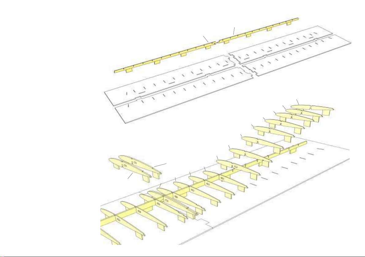
In a first step glue together main spar parts F1 A and F1 B. Use a
straight edge against the spar´s building tabs for proper alignment
and secure with tape.
Assemble the 4-part wing jig, place on a flat building board and
secure with tape.
2
Insert main spar in wing jig. Glue together centre ribs F2, then
glue ribs F2 to F14 to main spar as shown. Make sure that ribs are
fully seated in main spar and jig.
F1 B
F1 A
F14
F13
F12
F11
F10
F9
F8
F7
F2
F4
F2
F3
F6
F5
Page 4
3
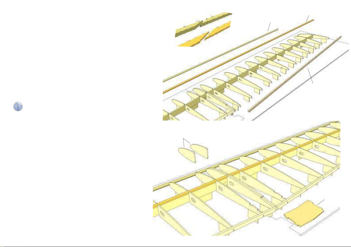
At one end only splice leading edge F15 (4×4 mm obechi)
and both spruce spars F16 (5×2 mm spruce) over a length
of ca. 15 mm. Leading edge and spars must have a length
of 1,110 and 1,150 mm, respectively.
Fit and glue in place upper spar F16. Glue leading edge
F15 to front of ribs and secure with pins inserted in wing
jig just in front of leading edge.
Slightly chamfer contact surface of both auxiliary spars
F17 at centre ribs and glue to rear end of ribs.
Note: Place large cut-out of F17 at wing centre.
i
4
Glue riblets F2 A to either side of centre ribs and secure
with small clamps. Then glue reinforcement F18 for wing
retaining screw to ribs and auxiliary spars.
F2 A
F15
F16
F15
F16
F17
F18
Page 5
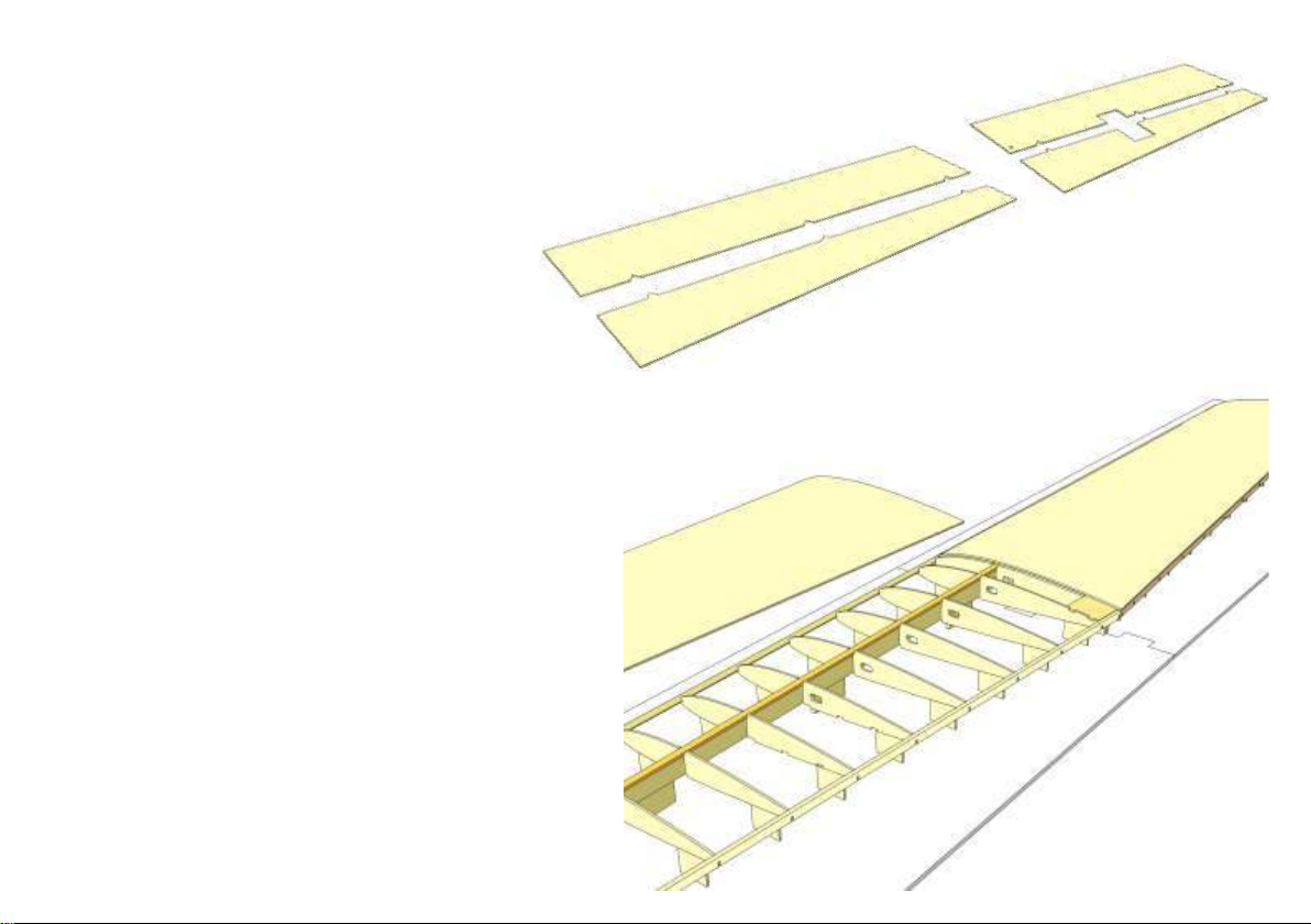
5
Glue together upper (F19 + F20) and lower (F21 + F22) wing
sheeting and place on a flat surface. Immediately remove any
excessive glue and secure with tape until dry.
6
Glue in place upper wing sheeting of each wing half in two steps.
Slightly chamfer front edge of upper wing sheeting for proper fit at
leading edge. Apply glue to contact surface of leading edge and
the first 5 mm of ribs. Fit upper wing sheeting in place on leading
edge and secure with tape. Leave to dry.
Apply glue to top of ribs (with the exception of centre ribs!), to
upper spruce spar and to auxiliary spar. Slightly press on wing
sheeting and secure with pins and tape. Make sure that wing
sheeting is in good contact with ribs.
Repeat for opposite wing half. When glue has dried, remove wing
from jig, turn upside down and from the inside apply glue to wing
sheeting at centre rib position. Replace wing in jig and secure
wing sheeting with pins and tape at centre rib position.
F21
F19
F22
F20
Page 6
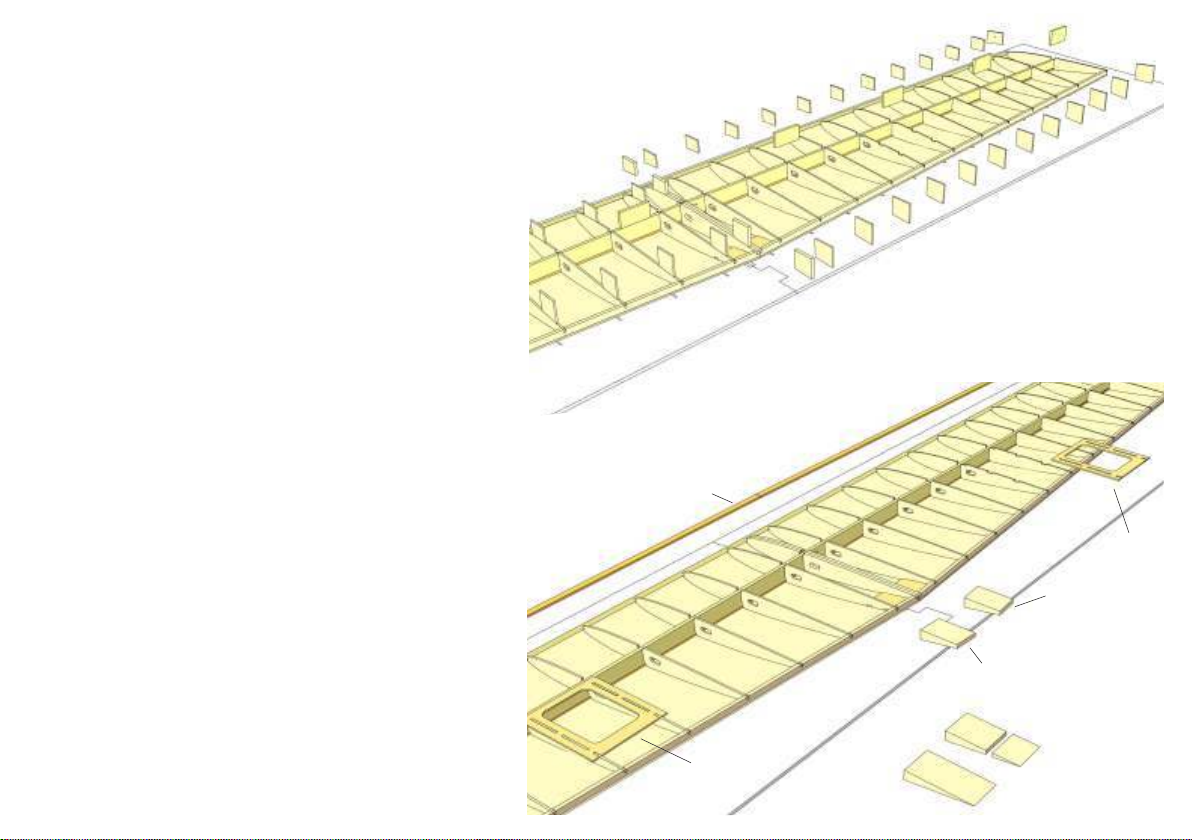
7
Remove wing from jig and turn upside down. Break off
building tabs and sand lightly to achieve a smooth
contact surface on main spar and ribs.
8
Glue in place lower spruce spar F16 and servo frames
F23.
F16
From trailing edge triangular stock (8×40 mm) cut off
two ca. 25 mm long pieces F24, then fit and glue in
place next to centre ribs as shown.
F23
F23
F24
F24
F24
Page 7
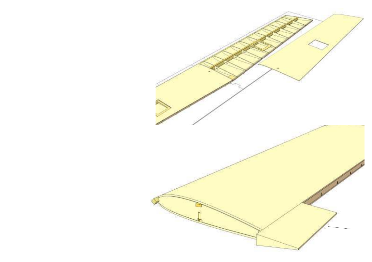
9
Install servo leads in wing and secure with tape in servo bay.
Route opposite end of servo leads through hole in lower wing
sheeting and glue wing sheeting in place.
Use same proceedrue as with upper wing sheeting.
10
Carefully sand flush rear edge of wing.
Cut off one ca. 80 mm long piece of either trailing edge
triangular stock F25 (8×30 mm) and glue to wing tip as
shown. Make sure that projection of end rib meets with
rear edge of trailing edge profile.
See also following building step.
F25
Page 8
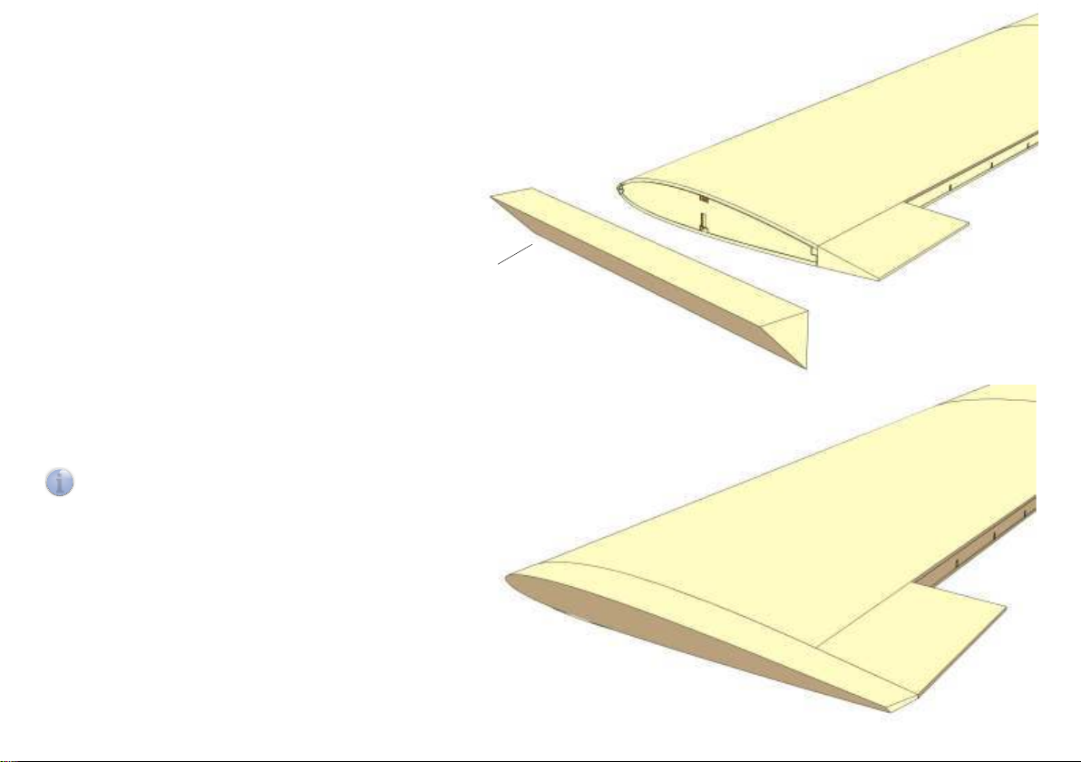
11
Cut off spars, leading and trailing edges at end ribs and
carefully sand flush with contact surfaces of end ribs. Glue
in place wing tips F26 (balsa triangular stock, 20×20 mm)
on end rib and secure with pins.
12
When dry, sand wing tips and leading edge to shape and
give wing a smooth surface.
Note: Wing tips are shaped automatically when upper and
i
lower wing sheeting are sanded to a smooth finish with a
sanding bar.
F26
Finally lightly chamfer edges of wing tips.
Page 9
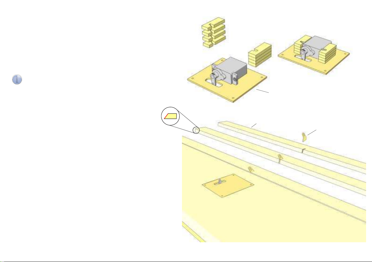
13
Glue together aileron servo mounts from 4 pieces F27
each. Align servo with servo arm centred in slot of servo
tray F28, hold in place and glue servo mounts in place
with a drop of medium CA.
Insert servo in servo mounts and install servo tray in wing.
Drill servo frame F23 with 1.5 mm and temporarily install
screws F31.
Note: Servo is held in place by servo mounts. No glue
i
required.
14
Bevel front edge of ailerons F29 (trailing edge triangular
stock 8×30 mm) and temporarily attach to wing with
tape.
Mark position of control horn F30 on aileron and cut slot
with razor saw or file into aileron. Glue control horn in
place after covering.
F27
F28
F29
F30
Page 10
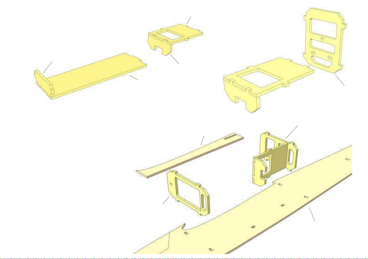
15
Glue former R5 at right angles into servo tray R4
and glue former R8 at right angles into R7.
Check with set square or similar.
R8
R4
16
Glue servo tray into former R3 at
right angles.
R5
R7
R3
17
Place right fuselage side R1 A on flat
building board and secure with pins.
Insert former R2 and assembly R3, R4, R5
in fuselage side. Do not glue!
Glue in place wing saddle R12 and make
sure contour matches contour of fuselage
side perfectly. Remove any excessive glue
from slot in R12.
R3, R4, R5
R12
R2
R1 A
Page 11
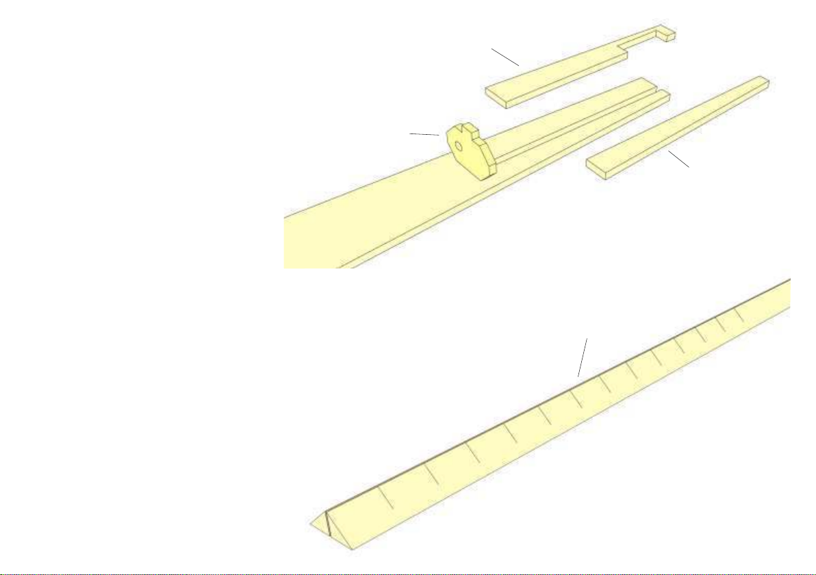
18
Glue reinforcements for tailplane slot R13 and R14 to
fuselage side. Temporarily insert former R11 into fuselage
side as an end stop.
19
Cut off two 375 mm and two 225 mm long pieces of 8×8 mm
triangular stock R15.
Place triangular stock on building board as shown and use a razor saw
to make cuts at intervals of 15 to 20 mm over a length of 200 mm.
This will make the triangular stock easier to bend when you glue it to
the fuselage side.
R13
R11
R14
R15
Page 12
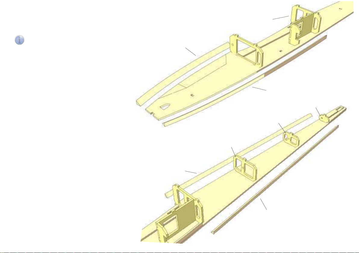
20
Glue triangular stock R15 on fuselage side along
top and bottom contours as shown and secure
with pins.
Note: Bottom strip ends in front of former R3.
i
R3
R15
R15
R11
21
Cut to length four pieces of 6×6 mm
triangular stock R16 for top and bottom
rear fuselage contours.
Temporarily insert formers R9 and R10
into right fuselage side, glue triangular
stock in place and secure with pins.
Remove formers R9, R10, R11.
R10
R9
R16
R16
Page 13
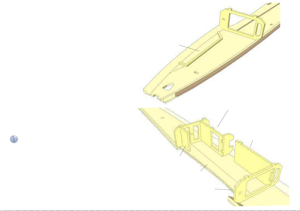
22
Glue in place canopy frame R17 on fuselage side
along canopy cut-out.
Remove any formers/assemblies from right
fuselage side and build up left fuselage side R1 B
accordingly.
23
Glue former R2 as well as assembly R3, R4, R5 in
place on right fuselage side.
R17
R3, R4, R5
Note: R2 is at right angles on fuselage side.
i
Glue in place battery tray R6, insert and glue wing
retainer R18 in slot in R12.
R6
R18
R12
R2
Page 14
24
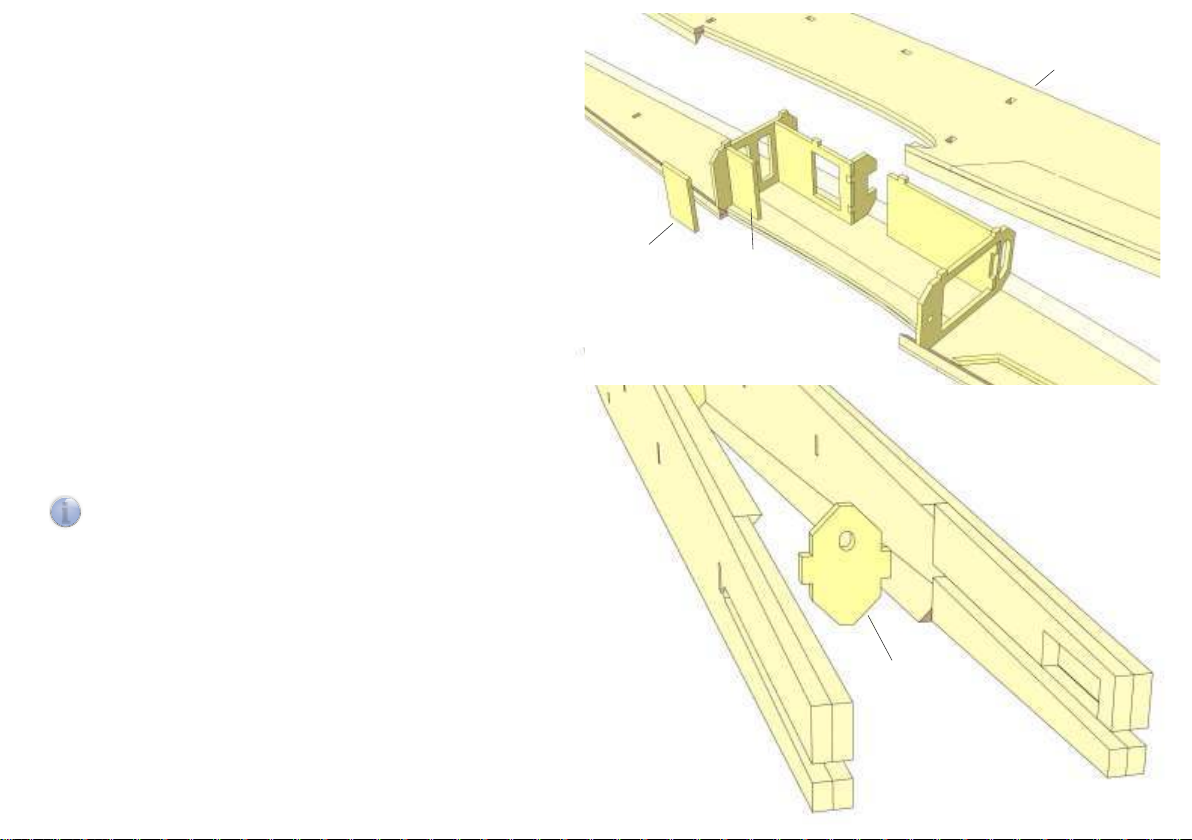
Make sure that left fuselage side R1 B fits perfectly on formers
before you glue. Make corrections as necessary.
Then glue in place left fuselage side on formers and glue R19
onto wing retainer R18.
R1 B
25
Glue former R11 into rear of fuselage (bore for elevator control
faces up), glue together rear end of fuselage sides without
sanding reinforcements R13, R14. Secure with clamps.
Note: Width at rear end of fuselage must not be reduced.
i
Elevator control exits between fuselage sides.
R19
R18
R11
Page 15
26
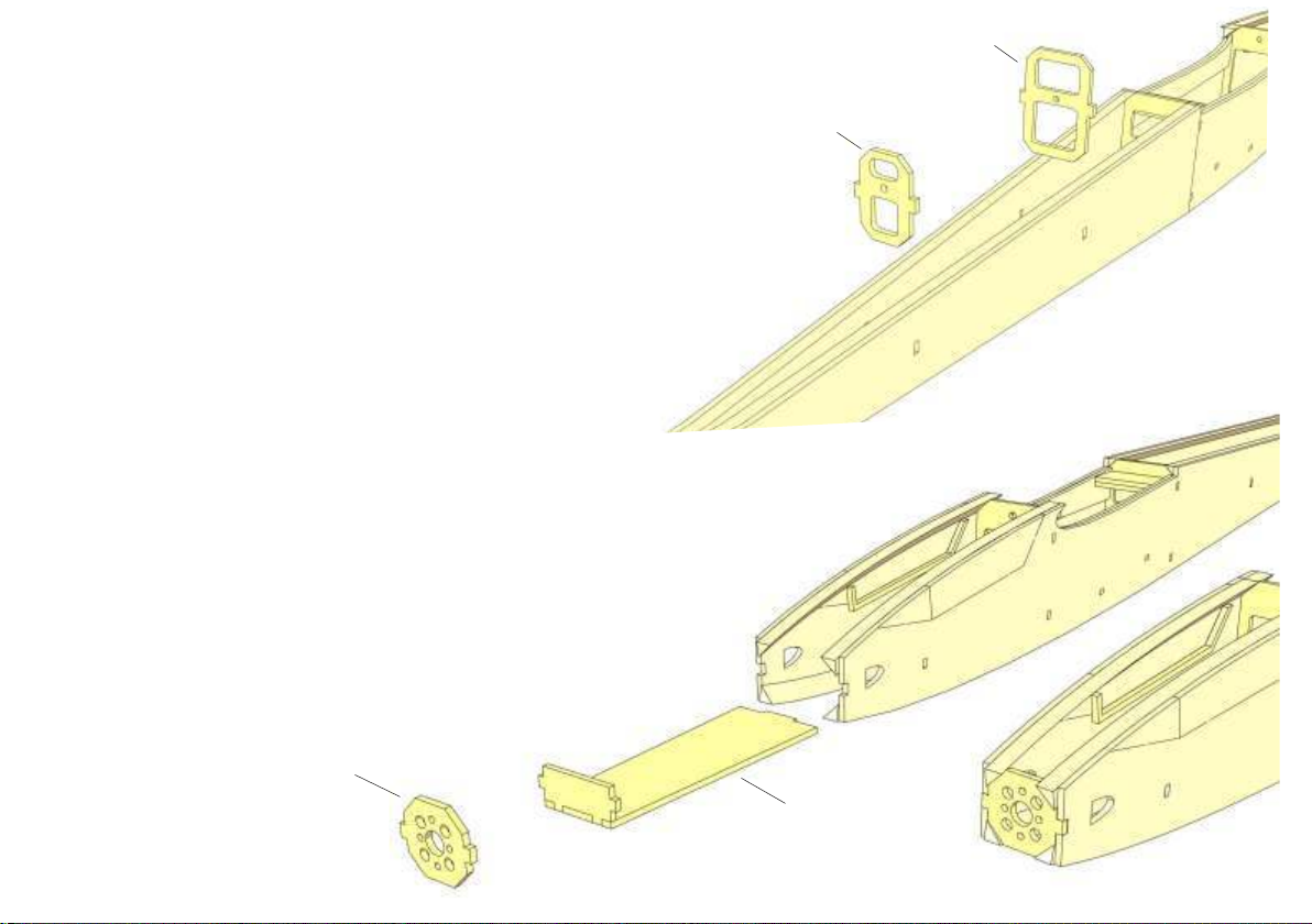
Glue in place formers R9 and R10. Please note that bores for
elevator control are located in upper half of formers.
R9
Secure with tape wrapped around fuselage.
27
Insert and glue R7/R8 into nose section, pulling together front of
fuselage sides. Glue in place motor mount R20 and secure with
clamps and tape.
R10
R20
R7/R8
Page 16
28
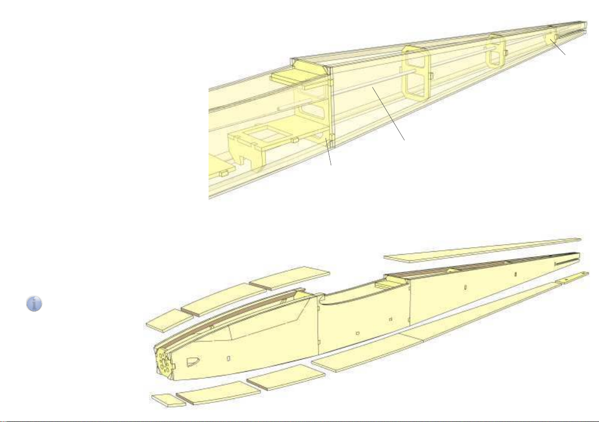
Cut snake outer R21 to a length of 485 mm and glue into
formers with 5 minute epoxy, so that it protrudes 30 mm from
former R3 and 45 mm from former R11.
29
Carefully sand top and bottom contact surfaces of fuselage, then
glue in place fuselage sheeting.
Upper and lower nose section sheeting consists of three pieces
each (R22 to R24 and R25 to R27) of 3 mm balsa. Upper rear
fuselage sheeting R 28 is one-piece, lower sheeting consists of
parts R29 and tail skid retainer R50.
R23
Note: Glue in place tail skid
i
R51 after covering.
R22
R11
R21
R3
R28
R24
R50
R29
R25
R27
R26
Page 17
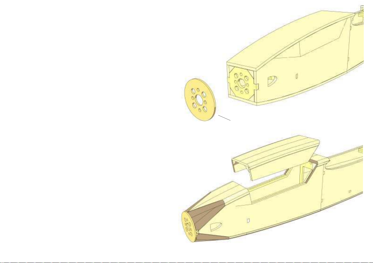
30
Cut off sheeting material and triangular stock and sand flush with
motor mount. Glue in place motor mount cover R30 (1.5 mm
birch ply). Make sure bores in R19 match bores in motor mount
perfectly.
When glue has dried, sand fuselage to shape and round off edges.
31
With a razor saw cut out canopy and remove from fuselage. Sand
contact surfaces until canopy rests on fuselage without binding.
R30
Page 18
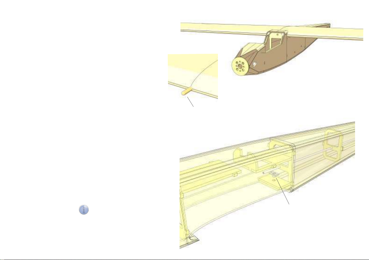
32
Fit wing into wing saddle and align with centre of fuselage.
Through bore in former R2 mark position of wing dowel, then
drill with 4 mm.
Insert wing dowel F32 in wing and slide wing in place on
fuselage. Make sure wing and dowel fit perfectly and without
binding.
Correct, if necessary, then glue dowel in place.
33
Position wing on fuselage and align with centre line.
12 mm from the rear of the wing drill with 4 mm through centre
of wing and into R18/R19. Drill through R18/R19 with 5 mm and
from below epoxy in place retaining nut R31.
F32
Note: Fuselage turned upside
i
down for clarity.
R31
Page 19
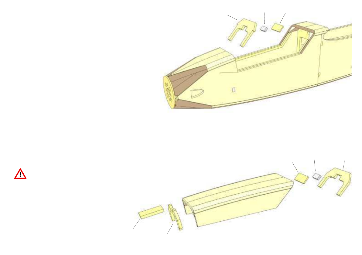
34
Fit canopy former R32 in place in fuselage. To achieve best
results, bevel off contact surfaces with upper sheeting,
triangular stock and canopy frame.
From behind glue magnet R33 and retainer R34 to former
(epoxy), then glue former R32 in place and secure with clamps.
35
Fit canopy former R35 in place in rear end of canopy. To achieve best results
bevel off contact surfaces with upper sheeting and triangular stock.
R32
R33
R34
From behind glue magnet R33 and retainer R34 to former (epoxy), then glue
former R35 in place and secure with clamps.
Attention: Make sure you check polarity of magnets before you glue!
At front end of canopy glue in place former R36 and retaining tab R37 and
secure with clamps.
R37
R36
R34
R33
R35
Page 20
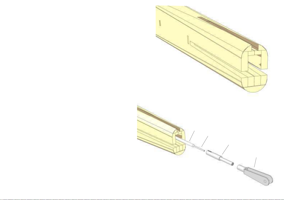
36
With drill and file make an opening in rear end of fuselage so that
clevis for elevator control can move freely and without binding
(ca. 6 mm wide, 7 mm high).
If necessary, correct opening when elevator control is installed.
37
Insert 0.8 mm piano wire R38 in snake R39.
Rough up snake at one end, epoxy or crimp clevis extender
R40 to snake and screw on clevis R41.
From the rear slide snake into snake outer. Make sure that
clevis moves freely and without binding between fuselage
sides.
R39
R38
R40
R41
Page 21
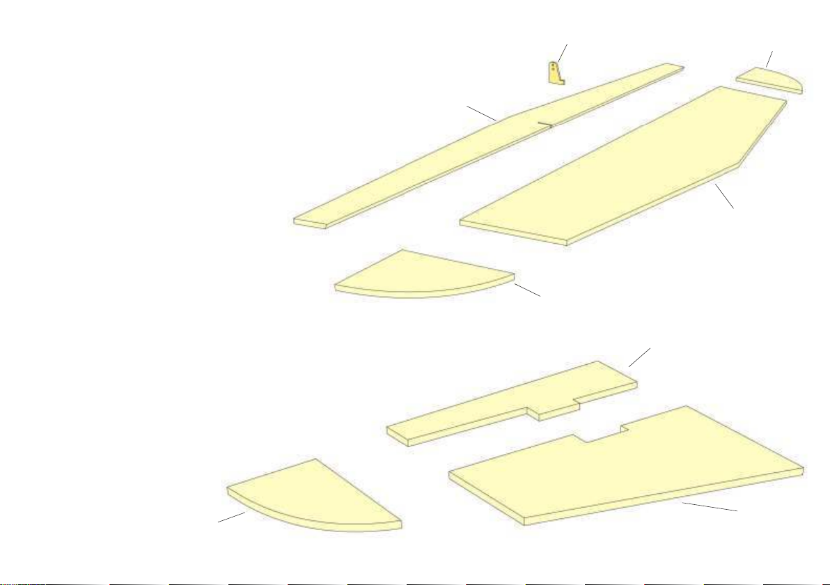
38
Place tailplane R42 on building board (put cling film under-
neath), secure with pins and glue tips R43 in place. Chamfer
front edge of elevator R44 for sufficient controll throw.
R45
R43
From above glue in place control horn R45 in elevator and sand
front of control horn flush with front edge of elevator.
39
Glue together fin from parts R46, R47 and R48.
Finally, round off front edges of tail assembly with sanding block.
R44
R42
R43
R47
R48
R46
Page 22
40
Completing the model
Mark contact surfaces of fin and tailplane and do not cover. Then cover components of model with your favourite covering material.
Iron-on film is the quickest method to achieve an attractive finish. Because of ist texture we suggest you use for your Pepper iron-on fabric, which is
available in many attractive colours. As an alternative you may want to cover your model with paper and apply a semi-gloss finish. Due to its low weight
and aerodynamic advantages this kind of finish will considerably enhance the model´s performance and flying characteristics.
In any case, we recommend you choose bright and contrasting colours for the model´s finish. This will make it easier to identify the model in the air.
Glue in place tail skid R51 in R50 (see building step 29). Attach elevator to tailplane with hinge tape (top and bottom!). Glue tailplane and fin in place.
From the rear slide elevator control snake into snake outer and attach clevis to control horn. Install pushrod connector R49 to elevator servo arm, install
servo and slide elevator control snake into connector.
Attach ailerons to wing with tape (top and bottom!). Install aileron servos in servo trays, install servo trays in wing and secure with screws F31. Install
clevises F34 on threaded pushrods F33, cut threaded rods to length and make a Z-bend at free end .
Install motor and radio equipment, connect servos and adjust to neutral position. Connect ailerons and elevator and adjust control throws. Control
throws for elevator are +/- 8 mm, for ailerons 8 mm up, 5 mm down.
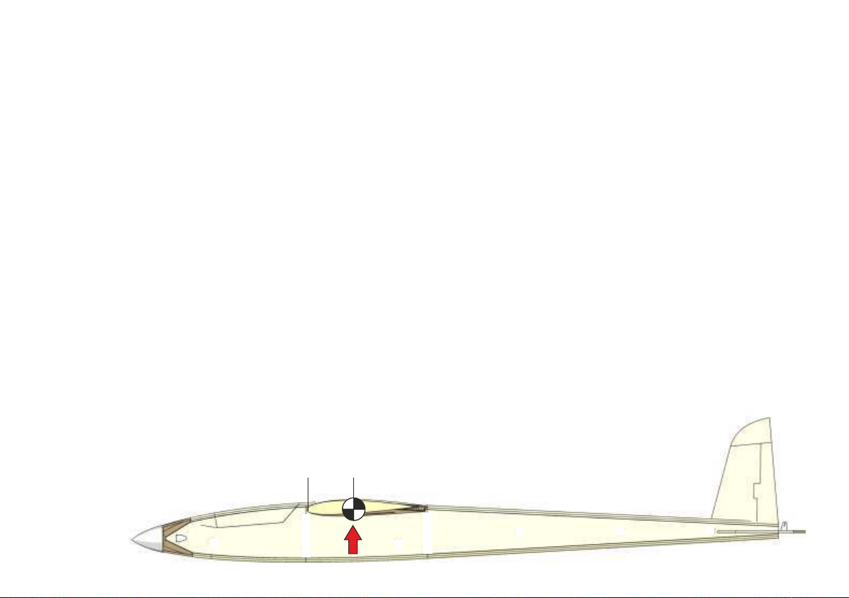
Place battery in fuselage beneath the wing and adjust centre of gravity (80-82 mm behind leading edge). Secure battery with hook abd loop tape at
established location.
Have fun with your Pepper!
Recommended settings
Centre of gravity: 80 - 82 mm behind leading edge
Elevator: 8/8 mm
80-82mm
Ailerons: 8 mm up, 5 mm down
Page 23
Parts List
P q0DescriptionPiecesMaterialSheetTypeDimensi ons
R1 A
right fuselage side
1balsa1laser-cut3 mm
R1 B
left fuselage side
1balsa2laser-cut3 mm
R2
former
1light ply5laser-cut3 mm
R3
former
1light ply5laser-cut3 mm
R4
servo tray
1light ply5laser-cut3 mm
R5
former
1light ply5laser-cut3 mm
R6
battery tray
1light ply5laser-cut3 mm
R7
cabin floor
1light ply5laser-cut3 mm
R8
former
1light ply5laser-cut3 mm
R9
former
1light ply5laser-cut3 mm
R10
former
1light ply5laser-cut3 mm
R11
former
1light ply5laser-cut3 mm
R12
wing saddle
2balsa1, 2laser-cut3 mm
R13
reinforcement tailplane slot
2balsa1, 2laser-cut3 mm
R14
reinforcement tailplane slot
2balsa1, 2laser-cut3 mm
R15
triangular stock
4balsacut part8 × 8 mm
R16
triangular stock
4balsacut part6 × 6 mm
R17
cabopy frame
2light ply5laser-cut3 mm
R18
wing retainer
1light ply5laser-cut3 mm
R19
doubler for wing retainer
1light ply5laser-cut3 mm
R20
motor mount
1light ply5laser-cut3 mm
R21
snake outer
1plasticcut part ▓▓
R22 - R24
top fuselage sheeting
je 1balsa3laser- cut3 mm
R25 - R27
bottom fuselage sheeting
je 1balsa3laser- cut3 mm
R28
top fuselage sheeting
1balsa3laser-cut3 mm
R29
bottom fuselage sheeting
1balsa3laser-cut3 mm
R30
motor mount cover
1birch ply6laser- cut1.5 mm
R31
wing retaining nut
1steelready madeM4
R32
canopy former
1light ply5laser-cut3 mm
R33
magnet
2metalready made10 × 6 mm
R34
magnet retainer
2birch ply6laser- cut1.5 mm
R35
canopy former
1light ply5laser-cut3 mm
R36
canopy former
1light ply5laser-cut3 mm
R37
retaining tab
1light ply5laser-cut3 mm
R38
elevator control
1piano wirecut part ▓▓
R39
snake, elevator control
1plasticcut part ▓▓
R40
clevis extender
1metalready madeM2
P q0DescriptionPiecesMaterialSheetTypeDimens ions
R41
clevis
1metalready madeM2
R42
tailplane
1balsa4laser-cut3 mm
R43
tailplane tip
2balsa4laser-cut3 mm
R44
elevator
1balsa4laser-cut3 mm
R45
control horn
1birch ply6laser- cut1.5 mm
R46
fin
1balsa4laser-cut3 mm
R47
fin
1balsa4laser-cut3 mm
R48
fin tip
1balsa4laser-cut3 mm
R49
pushrod connector
1metalready made ▓▓
R50
tail skid retainer
1light plylaser-cut3 mm
R51
tail skid retainer
1light ply5laser-cut3 mm
F 1 A, F1 B
main spar
je 1light ply5laser- cut3 mm
F2
centre rib
2balsa1, 2laser-cut3 mm
F2 A
riblet
2balsa3laser-cut3 mm
F3 - F14
rib
je 2balsa7, 8, 9, 10laser-cut1.5 mm
F 15
leading edge
1obechicut part4 × 4 mm
F 16
spar
2sprucecut part5 ▓▓
F 17
auxiliary spar
2balsa1, 2laser-cut3 mm
F 18
reinforcement w ing retaining screw
1birch ply6laser- cutĈBD ÖÖ
F 19
upper wing sheeting
2balsa7laser-cut1.5 mm
F 20
upper wing sheeting
2balsa8laser-cut1.5 mm
F 21
lower wing sheeting
2balsa9laser-cut1.5 mm
F 22
lower wing sheeting
2balsa10laser-cutĈBD ÖÖ
F 23
servo frame
2birch ply6laser- cut1.5 mm
F24
filler
2balsacut part8 × 40 mm
F25
trailing edge
2balsacut part8 × 30 mm
F26
wing tip
2balsacut part20 × 20 mm
F27
servo mount
16light ply5laser- cut3 mm
F28servo tray2birch ply6laser- cut1.5 mm
F29
aileron
2balsacut part8 × 30 mm
F30
control horn
2birch ply6laser- cut1.5 mm
F31
servo tray screw
8steelready made2.2 × 6.5
F32
wing dowel
1beechcut part ▓▓
F33
threaded rod
2metalready madeM2
F34
clevis
2metalready madeM2
F35
wing retaining screw
1plasticready madeM4
H
wing jig
10laser-cut
Page 24
Here are some more models from our range ...
Lilienthal 40 RC
Wingspan 1,190 mm
Free flying glider with
RC option
Laser-cut wood kit
designed with beginners,
schools and clubs in mind
Luscombe Silvaire 1369/00
Laser-cut wood kit
aero
naut
aero-naut Modellbau
Stuttgarter Strasse 18-22
D-72766 Reutlingen
Find many more at www.aero-naut.de
www.aero-naut.de
1336/00-E1-03/2019
 Loading...