

Aeromotive 18673 User Manual
18673, 19874 INSTALLATION INSTRUCTIONS
WARNING!
The fuel system is under pressure. Do not open the fuel system until the pressure has been relieved.
Refer to the appropriate vehicle service manual for the procedure and precautions for relieving the fuel system
pressure.
This pump assembly is a high performance factory replacement unit. Key features:
• Drops directly into the factory fuel tank (NO CUTTING REQUIRED).
• Utilizes the factory jet siphon system so it operates just like GM intended.
• High flow pre-filter built into inlet of pump.
• Includes fuel level mounting bracket for factory leveling unit.
NOTE: The use of Teflon braided line with machine crimped hose ends is recommended. This eliminates the
possibility of fuel vapors permeating through the fuel line. The use of a 16306 speed pump controller is also
highly recommended, this will keep the fuel cool and reduce noise inside the passenger compartment.
CAUTION:
Installation of this product requires detailed knowledge of automotive systems and repair procedures. We
recommend that this installation be carried out by a qualified automotive technician.
Installation of this product requires handling of gasoline. Ensure you are working in a well ventilated area
with an approved fire extinguisher nearby. Extinguish all open flames, prohibit smoking and eliminate all sources
of ignition in the area of the vehicle before proceeding with the installation.
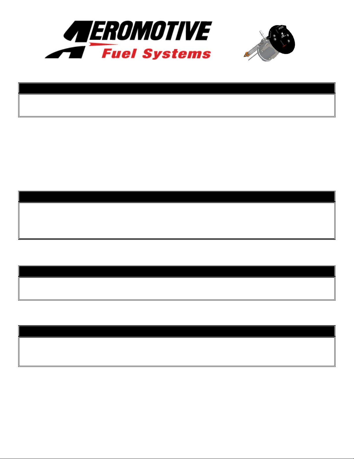
The enclosed Aeromotive fuel pump utilizes AN-08 ORB (O-ring Boss Ports) style outlet port and AN-08 return port; these
ports are NOT PIPE THREAD and utilize NO THREAD SEALANT.
NOTICE TO INSTALLER:
Installation of this fuel pump requires fuel system conversion to a return style fuel system (use of a bypass style regulator). Also note that a check engine light may be present after installation due to the factory
returnless system being modified. This can be turned off with tuning software.
NOTE: Due to tight clearance between the top of the fuel tank and body, Aeromotive includes fuel tank strap
spacers and high density foam to space the tank down.
Compatible Fuels:
Pump Gas
Race Gas
E85
Alcohol/Ethanol
Aeromotive Related LS Components:
Fuel Filters: Check Valves:
12301 (pump/race gas) 10 micron 15106 (6AN)
12335 (race gas/E85) 40 micron 15107 (10AN)
12305 (filter bracket)
Fuel Pressure Gauge:
Fuel Pressure Regulators: 15633 (dry 0-100psi)
13101 (10AN ports)
13109 (6AN ports) Fuel Rails:
14106 (LS1/LS6)
Electrical Components: 14114 (LS2)
16301 (pump wiring kit) 14115 (LS3/L76)
16306 (pump speed controller) 14142 (LS7)
14147 (LS1, Edelbrock 29085)
14156 (Platinum LS1/LS6)
TOP PLATE LAYOUT
The following steps are typical of most installations:
1. Disconnect the negative battery cable and drain the fuel tank.
2. Raise and support the vehicle.
3. Remove the exhaust and rear wheels from vehicle.
4. Remove driveshaft heat shield, drive shaft and fuel tank heat shield.
5. Remove the emergency brake cables from the three way tee and swing them towards the rear of the vehicle.
6. Remove the lower shock bolts.
7. Disconnect rear sub frame wiring located on passenger side frame rail.
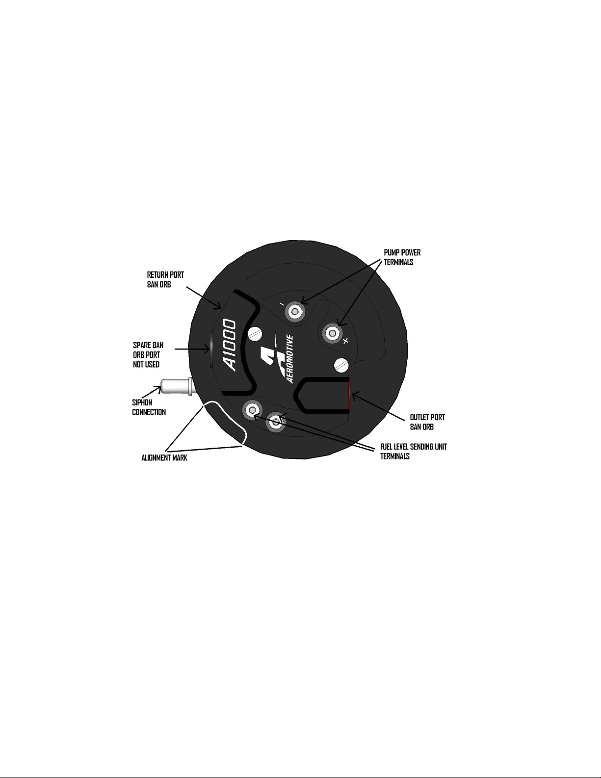
8. Disconnect all the following connections in Figure 1-1.
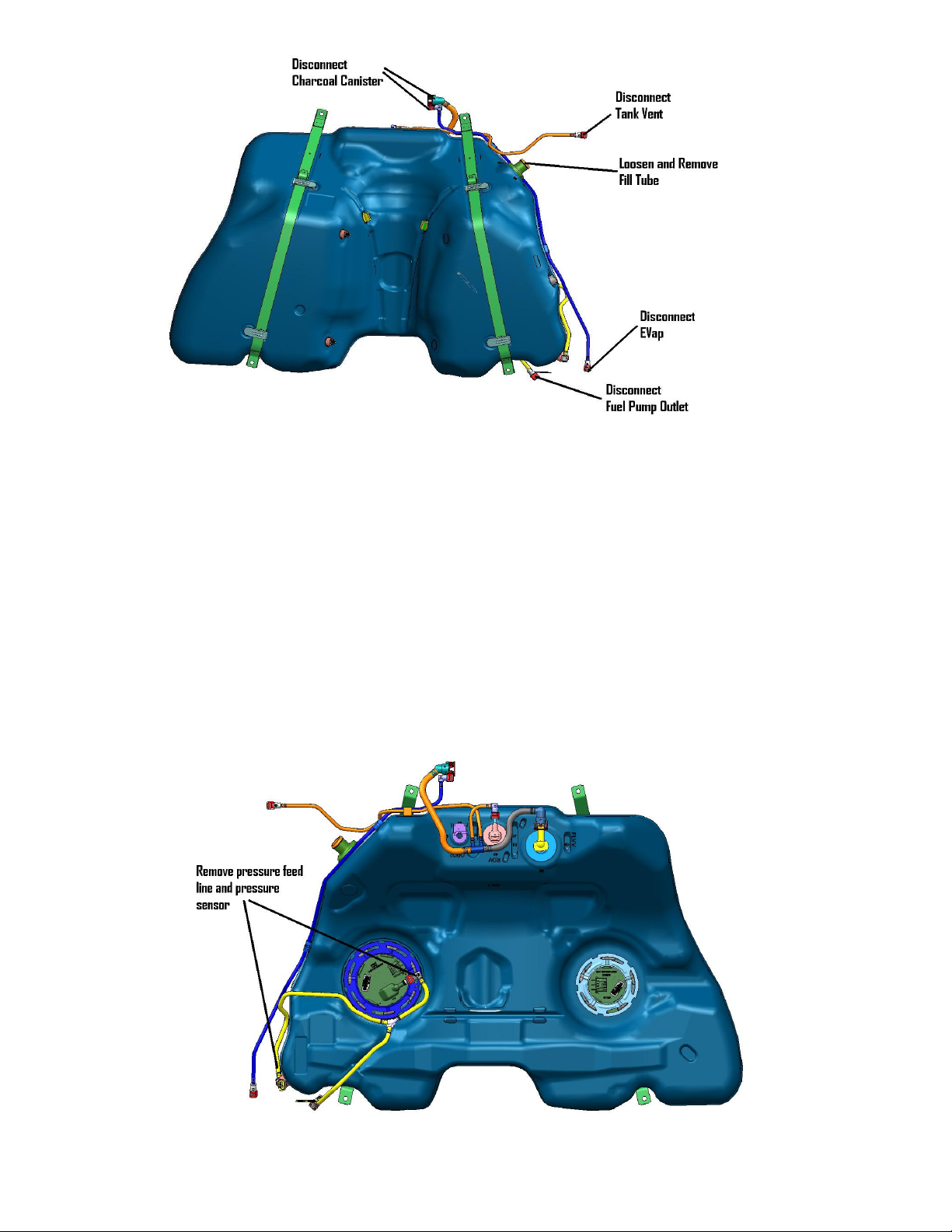
FIGURE 1-1
9. Support the rearend (complete IRS sub frame) with a suitable jack (transmission jack works best). Remove the four
24mm bolts that hold the sub frame in. Carefully lower the rearend, paying close attention to the brake lines on each
side of the frame. There is enough length on the brake lines to get the tank out without removing the calipers. Once
lowered, support the complete IRS sub frame with jackstands.
10. Remove the evap canister. This is done by unplugging all hoses and wires and removing the two 10mm bolts.
11. Unplug and remove the wiring harness connection at the tank on the passenger side.
12. Remove the fuel tank strap mounting bolts (15mm), tank straps and drop the tank out of the car. NOTE: It’s
recommend to do this with two people.
13. Now remove the pressure feed line and pressure sensor. Also remove the lock ring holding the fuel pump module in
place. NOTE: The fuel pump module is spring loaded and will pop up. FIGURE 1-2
FIGURE 1-2
 Loading...