

Aeromotive 18670 User Manual
18670, 19871 INSTALLATION INSTRUCTIONS
WARNING!
The fuel system is under pressure. Do not open the fuel system until the pressure has been relieved.
Refer to the appropriate vehicle service manual for the procedure and precautions for relieving the fuel system
pressure.
This pump assembly is a high performance factory replacement unit. Key features:
• Drops directly into the factory fuel tank (NO CUTTING REQUIRED).
• Utilizes the factory jet siphon system so it operates just like GM intended.
• High flow pre-filter built into inlet of pump.
• Includes fuel level mounting bracket for factory leveling unit.
NOTE: The use of Teflon braided line with machine crimped hose ends is recommended. This eliminates the
possibility of fuel vapors permeating through the fuel line.
CAUTION:
Installation of this product requires detailed knowledge of automotive systems and repair procedures. We
recommend that this installation be carried out by a qualified automotive technician.
Installation of this product requires handling of gasoline. Ensure you are working in a well ventilated area
with an approved fire extinguisher nearby. Extinguish all open flames, prohibit smoking and eliminate all sources
of ignition in the area of the vehicle before proceeding with the installation.
The enclosed Aeromotive fuel pump utilizes AN-10 ORB (O-ring Boss Ports) style outlet port and AN-06 return port; these
ports are NOT PIPE THREAD and utilize NO THREAD SEALANT.
NOTE: Due to tight clearance between the top of the fuel tank and body, Aeromotive includes the following
fittings:
Outlet fitting: 15690 Return fitting: 15689
Compatible Fuels:
Pump Gas
Race Gas
E85
Alcohol/Ethanol
Aeromotive Related LS Components:
Fuel Filters: Check Valves:
12301 (pump/race gas) 15106 (6AN)
12335 (race gas/E85) 15107 (10AN)
12305 (filter bracket)
Fuel Pressure Gauge:
Fuel Pressure Regulators: 15633 (dry 0-100psi)
13101 (10AN ports)
13109 (6AN ports) Fuel Rails:
14106 (LS1/LS6)
Electrical Components: 14114 (LS2)
16301 (pump wiring kit) 14115 (LS3/L76)
16306 (pump speed controller) 14142 (LS7)
14147 (LS1, Edelbrock 29085)
14156 (Platinum LS1/LS6)

The following steps are typical of most installations:
1. Disconnect the negative battery cable and drain the fuel tanks.
2. Raise and support the vehicle.
3. Remove the right rear tire and wheelhouse panel.
4. Disconnect the fuel pump module harness connector.
5. Remove the crossover tube from the clamp located above the transmission. FIGURE 1-1
FIGURE 1-1
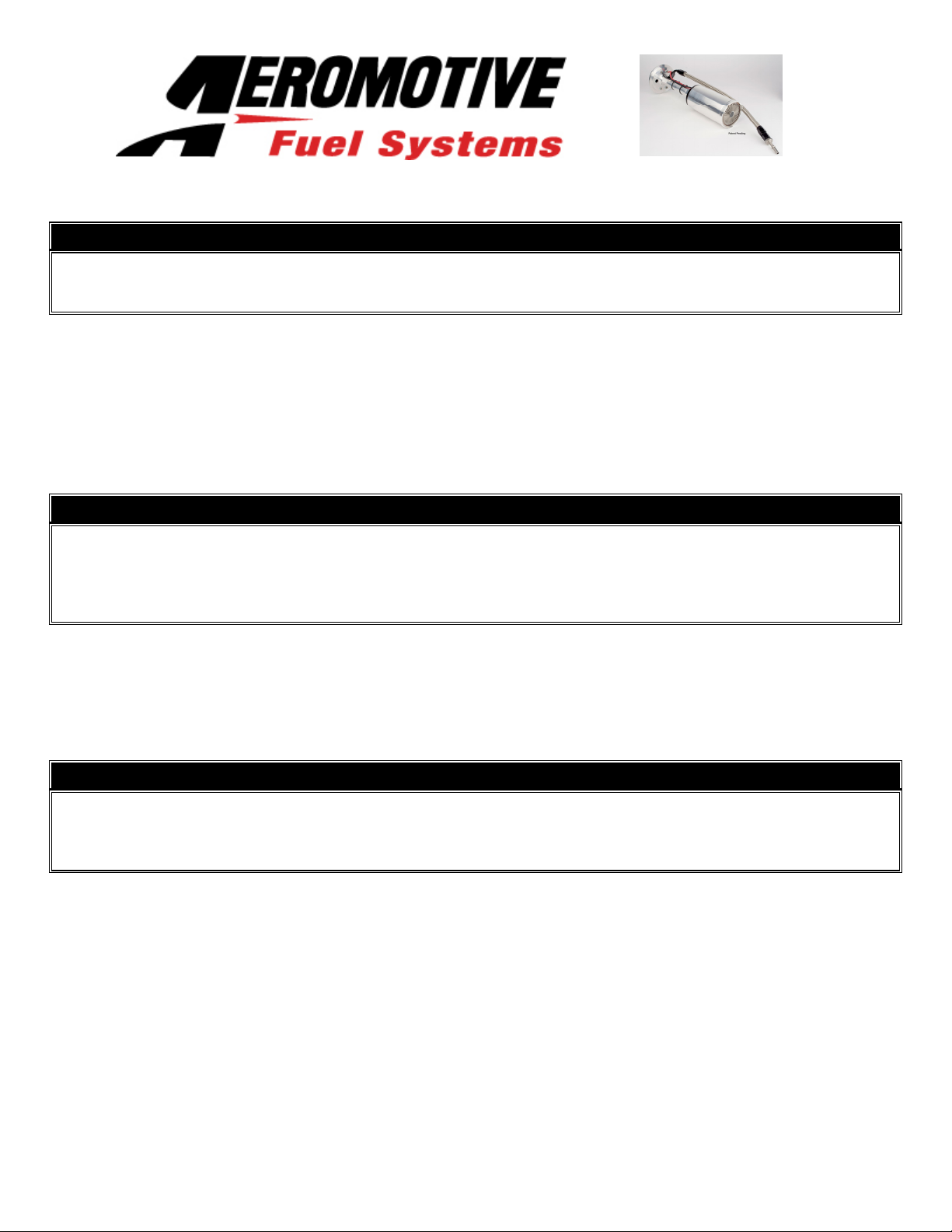
6. Removal of the driveline and exhaust may be necessary to remove the crossover tube. Once you have performed this
procedure, you will gain enough knowledge of the components that you may be able to do the procedure in the future
without lowering the driveline. You must slide the CPA ring aside so the collar can be turned counter clockwise.
FIGURE 1-2
FIGURE 1-2
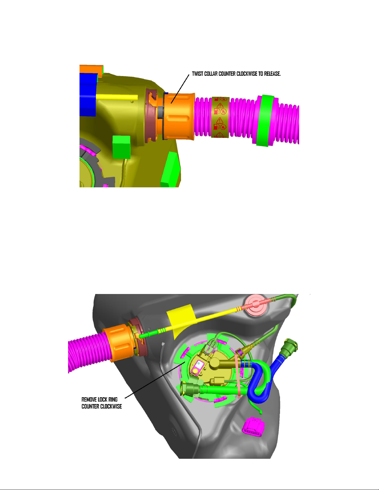
FIGURE 1-2
7. Once the collar has been released pull the cross over tube straight back, DO NOT TWIST. Twisting of the tube will
damage the small transfer tubes inside.
8. Repeat steps 3-7 for the other side.
9. Disconnect the EVAP Crossover pipe quick connect fitting at the top of each tank right above the crossover tube
connections and remove from vehicle.
10. Remove the fuel tank strap mounting bolts, tank straps and drop the tanks out of the car.
11. Remove the lock ring from the passenger side tank. The unit is spring loaded and will pop up once the ring is
removed. FIGURE 1-3
FIGURE 1-3
 Loading...