

Aeromotive 18668 User Manual
18668 & 18669 Installation Instructions
IMPORTANT INSTALL REQUIREMENTS:
1. Must have at least a 4.5” diameter flat surface on the fuel tank to install this
pump.
2. Minimum vertical install height of 9.75”.
3. Pump can not be mounted horizontal (TOP MOUNT ONLY).
4. Baffling required at the pickup point for pump longevity and performance.
CAUTION:
Installation of this product requires detailed knowledge of automotive
systems and repair procedures. We recommend that this installation be carried
out by a qualified automotive technician.
Installation of this product requires handling of gasoline. Ensure you are
working in a well ventilated area with an approved fire extinguisher nearby.
Extinguish all open flames, prohibit smoking and eliminate all sources of ignition
in the area of the vehicle before proceeding with the installation.
When installing this product, wear eye goggles and other safety apparel as
needed to protect yourself from debris and sprayed gasoline.
The enclosed pump uses ORB ports, they are NOT PIPE THREAD and utilize NO THREAD
SEALANT. You must install ORB port fittings with o-rings to seal the fitting into the pump.
Kit includes:
1 x A1000 fuel pump 1 x Pump Retainer Ring
1 x Filter Assembly 1 x Pump Gasket
1 x ¾ tube 10 x Pump mounting bolts
10 x Teflon washer’s 2 x Retainer ring mounting screws
1 x 10AN ORB tube clamp
Aeromotive system components are not legal for sale or use on emission controlled motor vehicles.
The following steps are typical of most installations:
1. On the top of the fuel tank find a 4.5” diameter flat area for fuel pump location (towards the rear of the
tank is the best location). Mark the center of this location so it can be cut out.
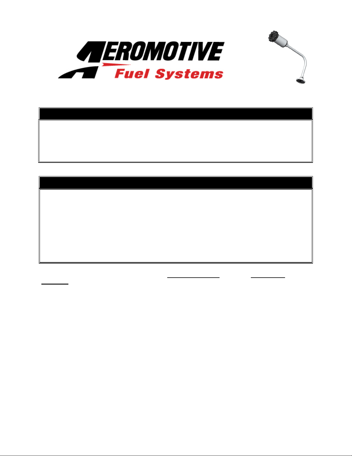
2. Use a 3.5” hole saw to cut out the pump hole. Lower the pump into the hole and use a transfer punch
to locate the 10 mounting holes. Remove the pump and drill the holes using a .225” drill bit. Drill two
more holes for the pump retainer ring 180 degrees apart. Refer to figure 1-1 for these two holes.
3. Now take an 82 degree chamfer tool and chamfer the two holes for the pump retainer ring. Once
finished it will look like figure 1-1.
FIGURE 1-1
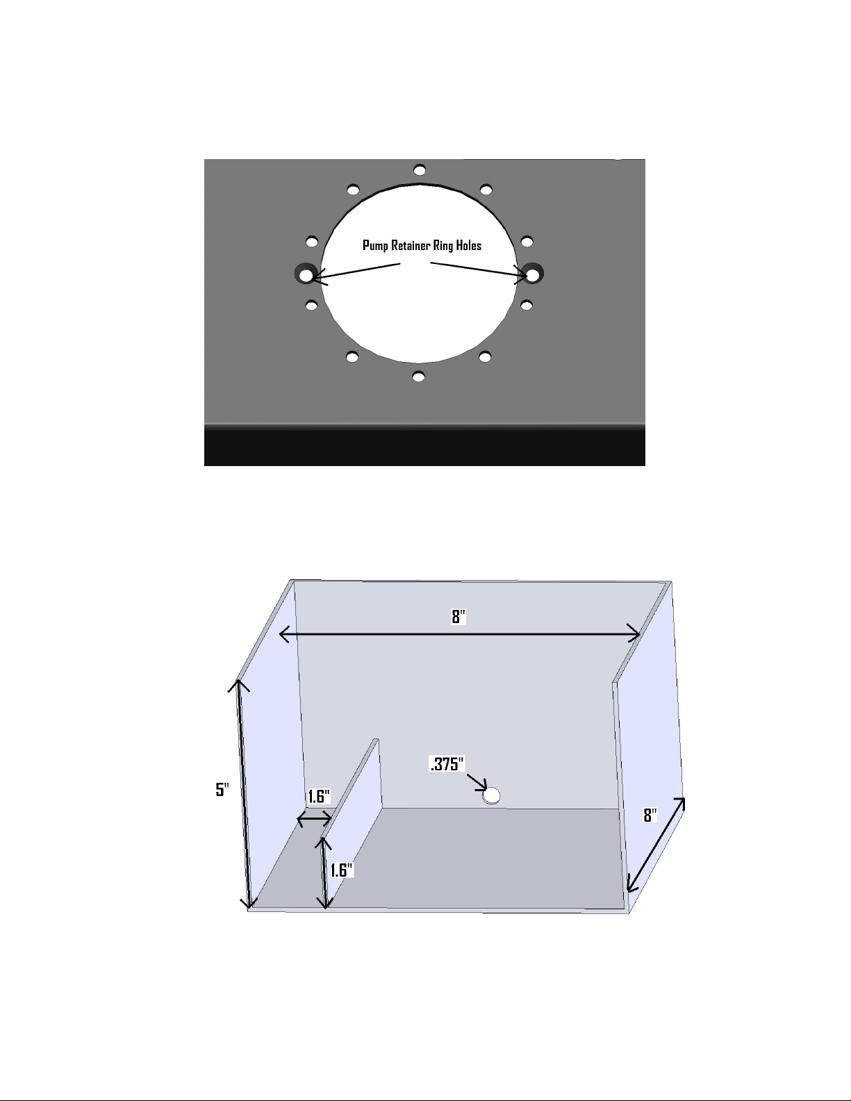
4. Construct baffling for the filter pick area. This is key for pump performance and longevity. Typical
baffling size is 8x8x5. Use figure 1-2 for reference.
FIGURE 1-2
5. Drill two .375” holes near the bottom of the baffling running from the front to rear of the vehicle. Also
construct an 8” x 1.6” x 1.6” wall along the bottom of the baffle box for the return to feed into. This will
keep the fuel calm at the pickup point and reduce the chance of cavitation. Figure 1-3
FIGURE 1-3
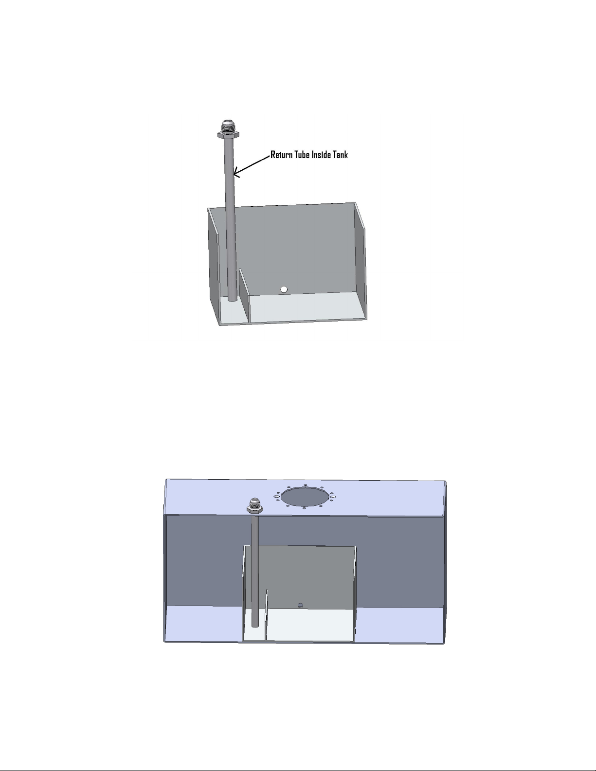
6. Typical position for the baffle box is below the fuel pump cut out. Although they can be mounted
apart. For this illustration we will use the most common. Position the baffle box below the fuel pump
cut out and secure it to the floor of the tank. When finished it will look like figure 1-4.
NOTE: Pump does not need to be mounted directly above the baffle box. It can be mounted
anywhere on the top of the tank as long as you can get a tube from the pickup filter
assembly to the inlet of the pump.
FIGURE 1-4
 Loading...